Advertisement
Introduction
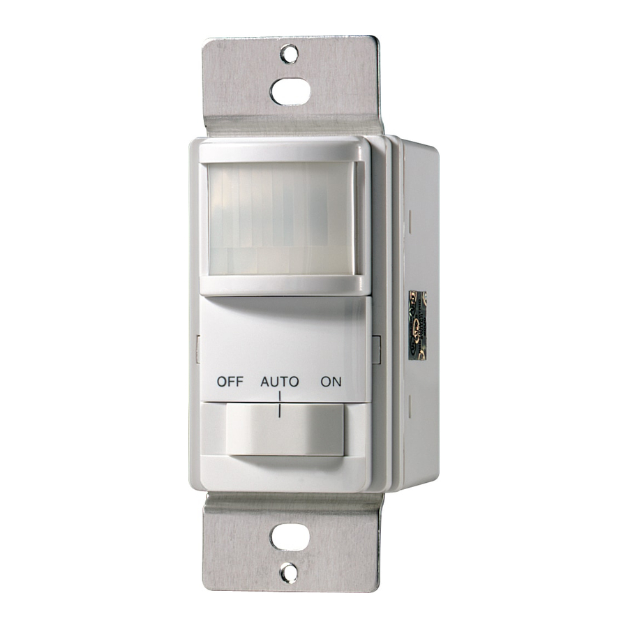
The 6107 Motion Sensing Wall Switch dectects motion to turn on lights for an adjustable amount of time. A built-in photo cell can be set to keep lights off when the lights aren't needed. The unit has excellent sensitivity and a wide 150° detection range. It can be used with incandescent lighting as well as rapid start fluorescent lighting. (Not for use with electronic ballasts).
The 6107 can be used to replace either a 3-way wall switch or a single pole switch. Some codes require installation by a qualified electrician.
Features include:
- 150° motion detection angle
- Adjustable on-time from 5 sec. to 20 min.
- Adjustable photocell
- Works with incandescent and rapid start fluorescent lighting (Not for use with electronic ballasts
- Works with motors up to 1/8 hp.
- Slide switch selectable OFF, ON AND AUTO modes.
Included are:
- The sensor switch
- Cover plate
- 4 wire connectors
- 2 large screws
- 2 small screws.
INSTALLATION

For indoor use only.
SELECT A LOCATION
- NEW APPLICATION
Choose a location where the motion sensor has a clear view of the entire area where occupant motion may occur.
![]()
- RETROFIT APPLICATION
Motion sensing switch will replace existing wall switch. Use only where the existing switch location provides a clear view of the occupied area. - GENERAL APPLICATION INFORMATION
The detector is more sensitive to motion across the front of the sensor than to motion towards the sensor.
The detector senses heat in motion and possible heat sources that change temperature quickly. Therefore, to avoid false triggering, avoid placing the sensor where it will be aimed at air conditioners, heaters, and other sources of heat or cold.

INSTALLING THE SWITCH
Turn power off at the circuit breaker before wiring.
Note:
a "3-way" circuit controls lights from two separate switches. If you want to use this product in a single switch circuit or if you want to install more than one motion sensing wall switch.
- Remove the decorative coverplate (secured by two screws).

- Remove Control Cover. (Press in with screwdriver. Swing out cover to remove to access adjustable screws.)
- Choose which switch will be replaced and remove it.
- For easier re-wiring later, mark the house wiring with tape indicating where the wire had been connected.
- Do not connect to neutral wire or damage to unit will occur and warranty will be void.
![]()
- Remove remaining 3-way switch from the junction box.
- Add the jumper wire to the common lug and to either one of the two switched lugs. Ifyou're not sure which lug is common, install the jumper on any two of the three wires, and test the jumper as explained on the next page.
Note: After jumper is installed, this switch will turn lights on only.


Test for correct common wire connection

- Connect the 6107 Motion Sensing Switch as shown in the diagram below:


3-Way Motion Sensor Wiring Diagram
- Mount the 6107 into the junction box with the two junction box screws.
- Turn the circuit breaker back on.
- Preset the controls: Time to minutes, Light level adjustment fully clockwise. Cover the lens with masking tape.• With the motion sensor in the "ON" position, turn the remote switch on and off several times. Go to step 1, 2, or 3, depending on results.
Turn power off at circuit breaker prior to making any wiring changes.

Single Switch Installation
- For single switch installations, connect the wall switch as shown here.


3-Way with Two Motion Sensors
If you want to have motion sensors at both 3-way switches, connect them as shown below. The minumum wattage may increase to 100 W for fluorescent and 50 W for incandescent lighting.
Dual 3-Way Motion Sensor Wiring Diagram

ADJUSTMENTS
TIME
There are 6 preset selections for the amount of time the lights stay on: Test (5 seconds), 1, 5, 10, 15, and 20 minutes. Use a small, phillips screw driver to adjust the TIME control. Turn the TIME control until it "snaps" into the desired time position.

Note:
Adjustment screws found under (off-auto-on) face plate.
LIGHT LEVEL
The sensor can be prevented from turning on lights when there is already enough light in the room. Use a small screw driver to set the light level using this diagram as a guide. In the fully clockwise position, the sensor turns on lights even in full daylight. In the fully counter-clockwise poition, the sensor only turns on lights when the surrounding light level is very low.
To adjust the photocell:
- When the light in the room is at the level you want the lights to turn on, set the switch to the AUTO position. Put the TIME control to the 5 second position.
- Put the LIGHT control to the minimum dark (fully counter-clockwise) position.
- Wait for the lights to turn off.
- Turn the LIGHT adjustment clockwise in very small steps and wait 2 seconds before moving your hand in front of the sensor. Repeat until the lights controlled by the sensor come on. The light will now come on when the light level is at or below the present level and motion is detected.
Complete Installation
- Replace control panel cover and install the decorative wall plate. In installations where the Cooper motion sensor switch is combined with other switches or outlets on an expanded box, a combination wall plate will need to be purchased. Various combination wall plates are available at Home Centers and Electrical Supply Stores.
- Slide the switch a couple of times to make sure it operates freely.
USE
- MODE Selection Switch
Moving the switch selects one of three modes of operation: OFF, AUTO, ON - OFF:Lights stay off.
- AUTO: Lights come on for time set when motion is detected and the light level is below the set level or when 3-way switch is manually switched.
- ON: Lights stay on continuously. Flipping 3-way switch has no effect.
TROUBLESHOOTING
If you have a problem with your Wall Switch, first follow this guide. If the problem persists, call the customer service hotline at 1-866-853-4293 between 8:00 AM and 700 PM ET weekdays.
| SYMPTOM | POSSIBLE CAUSE |
| Light does not come on in the AUTO mode. |
|
| Lights do not stay on in the Auto mode. |
|
| Light does not turn off. |
|
| Light comes on for no reason in the Auto mode. |
|
SPECIFICATIONS
| Electrical input | 120V, 60 Hz |
| Fluorescent Load - Not for electronic ballasts | (2) 30 Watt minimum 400 Watt maximum Rapid Start |
| Motor Load | 1/8 HP maximum |
| Incandescent | 500W at 120V AC |
| On-Time | Adjustable approximately 5 sec. to 20 min. |
| Photocell Sensor | From dull daylight to less than 1 FC |
| Coverage | up to 15 ft. at 150°, up to 30 ft. in front of the sensor |
YOUR COOEPRWIRING DEVICES ELECTRIC ASSEMBLED PRODUCT TWO YEAR LIMITED WARRANTY
For a period of 2 years from the date of purchase, Cooper Wiring Devices will replace or repair the motion sensing switch provided that it has not been subject to abuse, improper installation or improper use, and is returned prepaid to Cooper Wiring Devices Quality Control Department at 203 Cooper Circle, Peachtree City, GA 30269. If the product has been discontinued, replacement will be made with the nearest available equivalent model. This warranty does not cover consumables (such as fuses). Proof of purchase in the form of a bill of sale or receipted invoice that shows that the item is within the applicable warranty period must be presented to obtain the repair or replacement provided by the warranty. Repair or replacement as provided under this warranty is the exclusive remedy of the customer. Cooper Wiring Devices shall not be liable for any incidental or consequential damages for breach of any express or implied warranty on any of its products. Except to the extent limited or prohibited by applicable law, any implied warranty of merchantability or fitness for a particular purpose on this product is limited in duration to the duration of this warranty. Some states do not allow the exclusion or limitation of incidental or consequential damages, or allow limitations on how long an implied warranty lasts, so the above limitations may not apply to you. This warranty gives you specific legal rights and you may also have other rights which vary from state to state.

Documents / ResourcesDownload manual
Here you can download full pdf version of manual, it may contain additional safety instructions, warranty information, FCC rules, etc.
Download Cooper 6107 - Motion Sensing 3-Way Wall Switch Installation Manual
Advertisement


Need help?
Do you have a question about the 6107 and is the answer not in the manual?
Questions and answers