Table of Contents
Advertisement
Quick Links
U S E R G U I D E
UGC025/0905
RG Series Pumps
INTRODUCTION
•
Purpose of the User Guide
Read this so no one gets hurt
Specifications: RG Pump
•
Mechanical
•
Installation - Electrical
Electrical and the Transformer
Sequence of Operation without Idle Mode Valve
Corporate Office: 412.312.6000
•
How the guide is organized
•
DESCRIPTION
•
INSTALLATION
•
Unpacking the boxes
•
Installation with Idle Mode Valve-Mechanical
•
OPERATION
•
RG Pump Operation
l
Instant Access 24/7 (Parts and Service): 800.458.1960
•
Your responsibilities as a user
What is the RG Pump
•
Typical applications
•
Preparing for installation
•
Sequence of Operation without Idle Mode
www.conairnet.com
•
ATTENTION:
•
How it works
•
Installation -
•
Installation with Idle Mode Valve-
l
Parts and Service: 814.437.6861
•
•
Advertisement
Chapters
Table of Contents

Subscribe to Our Youtube Channel
Related Manuals for Conair RG Series


Summary of Contents for Conair RG Series
- Page 1 U S E R G U I D E UGC025/0905 RG Series Pumps INTRODUCTION • Purpose of the User Guide • How the guide is organized • Your responsibilities as a user • ATTENTION: Read this so no one gets hurt •...
- Page 2 Serial Number(s): Model Number(s): DISCLAIMER: The Conair Group, Inc., shall not be liable for errors contained in this User Guide or for incidental, consequential damages in connection with the furnishing, performance or use of this information. Conair makes no warranty of any kind with regard to this information, including, but not limited to the implied warranties of merchantability and fitness for a particular purpose.
-
Page 3: Table Of Contents
Ta b l e o f C o n t e n t s I n t r o d u c t i o n Purpose of the user guide ....... . 1-2 How the guide is organized . - Page 4 O p e r a t i o n Checking Rotation ........4-2 Sequence of Operation without Idle Mode .
- Page 5 S E C T I O N I n t r o d u c t i o n P u r p o s e o f t h e u s e r g u i d e ....1 - 2 H o w t h e g u i d e i s o r g a n i z e d .
-
Page 6: I N T R O D U C T I O N
P u r p o s e o f t h e U s e r G u i d e This User Guide describes the Conair RG Pump and explains step-by- step how to install, operate, maintain and repair this equipment. -
Page 7: Using The Rg Pumps
U s i n g t h e R G P u m p s Each RG Pump is designed to work within a central vacuum system consisting • Vacuum Receiver • Dust Collector • Central Loading Control(s) Separate instructions are provided for these devices and should be referred to as needed to fully understand the operation of the entire system. -
Page 8: At T E N T I O N
AT T E N T I O N : R e a d t h i s s o n o o n e g e t s h u r t We design equipment with the user’s safety in mind. You can avoid the potential hazards identified on this machine by following the procedures outlined below and elsewhere in the User Guide. -
Page 9: D E S C R I P T I O N
S E C T I O N D e s c r i p t i o n W h a t i s t h e R G P u m p s ? ....2 - 2 Ty p i c a l a p p l i c a t i o n s . -
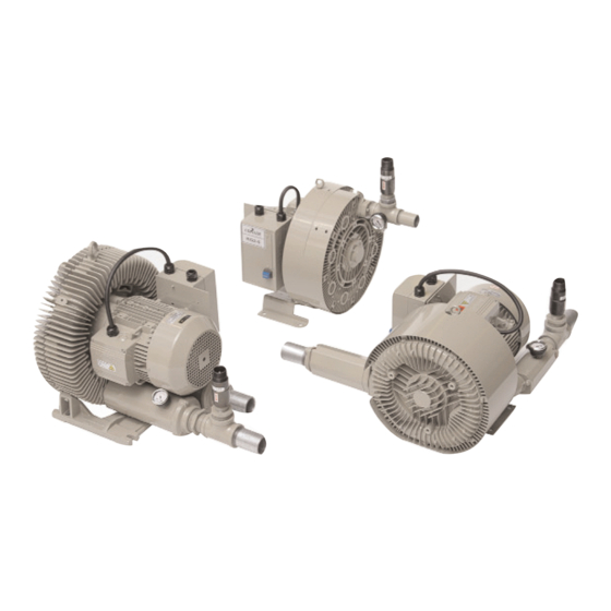
Page 10: What Is The Rg Pump
W h a t i s t h e R G P u m p s ? RG series vacuum pumps are vacuum pump and motor units designed to provide vacuum power for the conveyance of plastic pellets and regrinds through connec- tion with vacuum receivers and a dust collector. - Page 11 * Hp rating is based on the kW rating of the blower. Not comparable to positive Hp ratings. † Hg Vac. : Mercury Vacuum N/A: Not Available. Specifications can change without notice. Contact your Conair representative for the most current information. D e s c r i p t i o n l 2 - 3...
-
Page 13: I N S T A L L A T I O N
S E C T I O N I n s t a l l a t i o n U n p a c k i n g t h e b o x e s ....3 - 2 P r e p a r i n g f o r i n s t a l l a t i o n . -
Page 14: Unpacking The Boxes
U n p a c k i n g t h e B o x e s RG pumps are typically shipped bolted to a pallet and either enclosed by a box or WARNING: You are responsible for the simply wrapped in protective plastic sheeting. structural integrity of this installation. -
Page 15: Installation - Mechanical
I n s t a l l a t i o n - M e c h a n i c a l Use the lifting hook on the top of the pump to gently lower it into its oper- ating location. -
Page 16: Installation - Electrical
I n s t a l l a t i o n - E l e c t r i c a l A 3 phase, fused disconnect switch is typically provided near the pump loca- tion and matched to the voltage and full load amps of the pump, listed on its serial tag. -
Page 17: Installation With Idle Mode Valve - Mechanical
I n s t a l l a t i o n w i t h I d l e M o d e Va l v e - M e c h a n i c a l The Idle Mode Valve provides ambient air relief to the pump for 5 minutes after running, to eliminate rapid stop and start cycles from damaging the pump. -
Page 18: Electrical And The Transformer
I n s t a l l a t i o n w i t h I d l e M o d e Va l v e - E l e c t r i c a l a n d t h e Tr a n s f o r m e r The Transformer/Idle Mode Control is mounted next to and interconnected with the pump's starter and provides both a transformer for 120 volts from the 3 phase pump supply as well as a control for the Idle Mode Valve. - Page 21 S E C T I O N O p e r a t i o n C h e c k i n g R o t a t i o n ....4 - 2 S e q u e n c e o f O p e r a t i o n w i t h o u t I d l e M o d e .
-
Page 22: Checking Rotation
Upon confirming proper rotation, reconnect power and complete the tubing installation for operation. The RG series vacuum pumps operate in response to signals provided from a load- ing control, located elsewhere, and wired to the pump starter or the Transformer /Idle Mode Control. -
Page 23: Sequence Of Operation Without Idle Mode Valve And Control
Sequence of Operation with Idle Mode Valve and Control The loading control system determines the need for vacuum power for conveying. The Vacuum start signal (120 VAC or 24 VDT) from the loading control is sent to the Idle Mode Control box, next to the pump starter and the Idle Mode Control, in turn sends the signal to the pump starter to operate the pump. -
Page 25: M A I N T E N A N C E
S E C T I O N M a i n t e n a n c e M a i n t e n a n c e ..... . . 5 - 2 M a i n t e n a n c e l 5 - 1... - Page 26 M a i n t e n a n c e No regular maintenance is required for the RG series pumps. The pump and motor housings may be cleaned with common cleaning prod- ucts. In the event the fins become coated with dust, fluff or any other accumu- lation, they should be thoroughly cleaned out to maintain air cooling.
-
Page 27: Tr O U B L E S H O O T I N G
S E C T I O N Tr o u b l e s h o o t i n g B e f o r e B e g i n n i n g ....6 - 2 C o n v e y i n g P r o b l e m s . -
Page 28: Before Beginning
B E F O R E B E G I N N I N G You can avoid most problems by following the recommended installation and maintenance procedures outlined in this User Guide. If you do have a problem, this section will help you determine what caused it and how to fix it. Before you begin troubleshooting: Find the wiring diagrams that were shipped with your equipment. - Page 29 WARNING: Disconnect power and air sources. Always disconnect the pump from the loading control, main power source, compressed air source and before servic- ing. This prevents the pump from starting during servicing, which could cause per- sonal injury from flying debris or moving parts. Problem Possible cause Solution...
- Page 30 WARNING: Disconnect power and air sources. Always disconnect the pump from the loading control, main power source, compressed air source and before servic- ing. This prevents the pump from starting during servicing, which could cause per- sonal injury from flying debris or moving parts. Problem Possible cause Solution...
- Page 31 Tr o u b l e s h o o t i n g l 6 - 5...
-
Page 32: Appendix
We ’ r e H e r e t o H e l p Additional manuals and prints for Conair has made the largest investment in customer support in the plastics indus- your Conair equipment may be try. Our service experts are available to help with any problem you might have ordered through the Customer installing and operating your equipment. -
Page 33: Equipment Guarantee
(except for parts that are typically replaced after normal usage, such as filters, liner plates, etc.). Conair’s guarantee is limited to replacing, at our option, the part or parts determined by us to be defective after examination. The customer assumes the cost of transportation of the part or parts to and from the factory.
Need help?
Do you have a question about the RG Series and is the answer not in the manual?
Questions and answers