
Subscribe to Our Youtube Channel
Related Manuals for Sunways STE-BS5


Summary of Contents for Sunways STE-BS5
- Page 1 User Manual STE-BS Li-HV System S U N W A Y S T E C H N O L O G I E S C O . , L T D .
-
Page 2: Table Of Contents
1 Preface ……………………………………………………… 1.1 Overview ………………………………………………………………………… 5 1.2 Target Groups …………………………………………………………………… 5 2 Safety Instructions ……………………………………… 2.1 Safety Notes ……………………………………………………………………… 6 2.2 Important Safety Matters ……………………………………………………… 6 2.3 Environmental Conditions …………………………………………………… 9 2.4 Statement ………………………………………………………………………… 9 2.5 Symbol on the Battery Label ……………………………………………… 10 2.6 Symbol on the Packing Box …………………………………………………... -
Page 3: Preface
The products, services or features purchased are subject to the commercial contracts referred to as the battery or STE-BS battery). It mainly introduces the assembly, and terms of Sunways Technologies Co., Ltd. All or part of the products, services or installation, electrical connection, debugging, maintenance and troubleshooting of features described in this document may not be within purchased. -
Page 4: Safety Instructions
Sunways certified installers. Warning Sunways assumes no liability for injury or property damage due to repairs attempted by unqualified individuals or a failure to properly follow these instructions. These warnings Do not attempt to open, disassemble, repair, tamper with, or modify STE-BS Battery. -
Page 5: Environmental Conditions
※ 2.4 Statement Caution Sunways Technologies Co.,Ltd. has the right not to undertake quality assurance in any of the following circumstances: Do not connect STE-BS Battery directly to photovoltaic (PV) solar wiring. ① Damages caused by improper transportation. -
Page 6: Symbol On The Battery Label
※ 2.5 Symbol on the Battery Label If fire, switch off the breaker on DC side and stay away from battery. Sunways Technologies Co.,Ltd. has the right not to undertake quality assurance in any of the following circumstances: ① Damages caused by improper transportation. -
Page 7: Symbol On The Packing Box
The STE-BS series is a stackable mounted energy storage battery. 3.1.2 Models Handle with care. The STE-BS series battery includes 9 models which are listed below: STE-BS5, STE-BS7, STE-BS10, STE-BS12, STE-BS15, STE-BS17, STE-BS20, STE-BS23, STE-BS25. This side up. Keep dry. Stacked layers. -
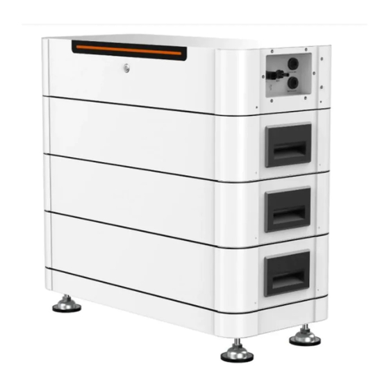
Page 8: Battery Introduction
4 Battery Introduction Item Terminal Note ※ 4.1 Appearance Introduction Battery MCB Control battery output 4.1.1 Control Module Battery output + Battery output - Service COM Specified Debug Interface Inverter COM Connect to the inverter communication port Power button Turn the battery on and off Left side view Right side view Figure 4-2 Battery Module... -
Page 9: Packing List
※ 4.2 Packing List Battery Plug×1 PE Termina×1 The package of the battery includes the following accessories. Please check whether the accessories in the packing box are complete when receiving the goods. See Figure 3-7 for the packing list. Control Module×1 Battery Module×2~10 STE-M2560-S STE-P2560-S... -
Page 10: Installation
5 Installation ③ Distance between base and wall is 20mm~120mm. ※ 5.1 Location 20mm-120mm ① The area is completely water proof. The floor is flat and level. ② There are no flammable or explosive materials. ③ The ambient temperature is within the range from 0 to 50. ④... - Page 11 Wall Figure 5-4 Place the battery modules Figure 5-6 Mark the position ② Install the fixings on both sides of the control module. ④ Remove the control module. Figure 5-5 Install the fixings ③ Use the fixings as the template to mark the position of 4 holes on the wall. Figure 5-7 Remove the control module...
- Page 12 ⑦ Place the control module on battery module. ⑤ Use an electrical driller with 10mm diameter bit to drill 4 holes in the wall with 80mm depth. Hole depth:80mm Figure 5-8 Drill holes Figure 5-10 Place the control module Before drilling, make sure to avoid any buried water tube and electric wires in the wall. ⑧...
- Page 13 ⑨ Insert the expansion screws into the holes, then fix the fixings onto the wall with 5.2.3 Ground Connection expansion screws by using a cross screwdriver. Proper grounding is good for resisting surge voltage shock and improving EMI performance. Battery must be well-grounded. For a system with only one battery, the PE cable needs to be grounded.
-
Page 14: Electrical Connection
① Select an appropriate DC cable. Do not use other brands or other types of terminals other than the terminals in the accessory package. Sunways has the right to refuse to held liable of all damages caused by the mixed-use of terminals. - Page 15 ③ Use a flathead screwdriver to open the clamping bracket in the connector, as shown in ① Before making the battery connector, please make sure the polarity of the cable is Figure 5-17: correct. ② Use a multimeter to measure the voltage of the battery pack and make sure the Warning voltage is within the inverter limitation and the polarity is correct.
-
Page 16: System Start And Stop
6 System Start and Stop Item Service COM Inverter COM RS485_A ※ 6.1 Start System RS485_B When starting the system, follow these steps: ① Turn on the DC Switch in the bottom of inverter. CAN_H ② Turn on the DC Switch on the control module. CAN_L RS232_RX RS232_TX... -
Page 17: Stop System
Restart the battery only after removing the fault that impairs safety performance. ⑤ Disconnect the AC and DC cables. Never arbitrarily replace any internal components. For any maintenance support, please contact Sunways. Otherwise, Sunways shall not be held liable for any damage caused. Attention... -
Page 18: Battery Storage
7) Handle batteries with caution to avoid damage. 8) Inappropriate storage will cause the battery performance and service life may be affected. Sunways Technologies Co.,Ltd. has the right not to undertake quality assurance in irregular storage. Ensure that batteries are stored indoors. Install batteries in a dry, clean, and ventilated environment that is free from sources of strong infrared or other radiations, organic solvents, corrosive gases, and conductive metal dust. -
Page 19: Storage Duration Overdue And Recharge
※ 8.2 Storage Duration Overdue and Recharge Do not store batteries for extended periods. Otherwise, the battery performance and Risk of battery damage or personal injury due to incorrect service!Dispose of bulged, service life may be affected. deformed, damaged, or leaking batteries irrespective of how long they have been stored. ·... -
Page 20: Troubleshooting
If any battery fault occurs, record the fault information, shut down the battery according manufacturer. Failure to Check whether the light Visual Warning to the shutdown procedure, and contact the distributor or Sunways. Do not handle the check is normal. inspection fault by yourself. -
Page 21: Technical Parameters
10 Technical Parameters Model STE-BS12 STE-BS15 STE-BS17 Nominal Capacity (KWh) 12.8 15.36 17.92 Model STE-BS5 STE-BS7 STE-BS10 Nominal Capacity (Ah) Nominal Capacity (KWh) 5.12 7.68 10.24 Nominal Voltage (V) 307.2 358.4 Nominal Capacity (Ah) Maximum Charge/ Discharge Current (A) Nominal Voltage (V) 102.4... - Page 22 Model STE-BS20 STE-BS23 STE-BS25 Nominal Capacity (KWh) 20.48 23.04 25.6 Nominal Capacity (Ah) Nominal Voltage (V) 409.6 460.8 Maximum Charge/ Discharge Current (A) Recommend Continuous Charge/ Discharge Current (A) Weight (Kg) 304.7 369.3 Dimension[W*H*D] (mm) 708*1576*315 708*1736*315 708*1896*315 Protection Degree IP54 Cycle Life 6,000 cycles @80% DOD...
- Page 23 No. 1, Second Road, Green Industrial Zone, Chongshou Town, Cixi City, ZheJiang Province, PRC www.sunways-tech.com service@sunways-tech.com...
Need help?
Do you have a question about the STE-BS5 and is the answer not in the manual?
Questions and answers