
Related Manuals for Sunways STT 50KTL


Summary of Contents for Sunways STT 50KTL
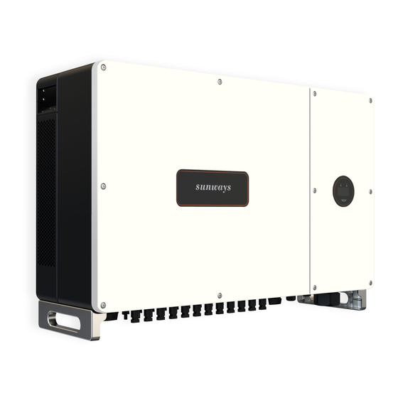
- Page 1 User Manual Grid-connected Inverter STT 50~60KTL S U N W A Y S T E C H N O L O G I E S C O . , L T D .
-
Page 2: Table Of Contents
1 Preface ……………………………………………………… 1.1 Overview ………………………………………………………………………… 5 1.2 Target Groups …………………………………………………………………… 5 2 Safety Instructions ……………………………………… 2.1 Safety Notes ……………………………………………………………………… 6 2.2 Statement ………………………………………………………………………… 6 2.3 Important Safety Matters ……………………………………………………… 7 2.4 Symbols Explanation …………………………………………………………… 8 3 Product Description ……………………………………… 3.1 Basic Features …………………………………………………………………... -
Page 3: Preface
The products, services or features purchased are subject to the commercial contracts ※ 1.2 Target Groups and terms of Sunways technologies Co., Ltd. All or part of the products, services or This manual is applicable to the electrical installers with professional qualifi cations and features described in this document may not be within purchased. -
Page 4: Safety Instructions
Danger ※ 2.2 Statement Potentially dangerous situation, if not avoided, may result in death or serious personal Sunways Technologies Co.,Ltd. has the right not to undertake quality assurance in any of injury. the following circumstances: Warning ①... -
Page 5: Symbols Explanation
2 Safety Instructions 2 Safety Instructions 2.4.2 Symbol on the Inverter nameplate The safety warning information about equipment or environment, to prevent equipment damage, data loss, equipment performance degradation or other unpredictable results. Attention The inverter cannot be disposed of with household waste. Symbol highlights important information, best practices and tips, etc. -
Page 6: Product Description
Handle with care. The applicable grid types for the Sunways STT 50-60kW series are TN-S, TN-C, TN-C-S, IT and TT. When ap- plied to the TT grid, the voltage of N to PE should be less than 30V.For more details please see Figure3-1:... -
Page 7: Physical Layout
3 Product Description 3 Product Description 3.2.2 Inverter side view 3.1.4 Storage conditions ① Inverter must be stored in its original packaging. 297mm ② The storage temperature and humidity should be in the range of -30℃ and+ 60℃ , and less than 90%, respectively. -
Page 8: Display Interface
Wiring terminals are at the bottom of the inverter, as shown in the table below. Item Terminal Note DC Input terminal PV connector COM 1 Port WiFi/LAN/GPRS/4G device connector sunways COM 2 Port RS485/DRED connector AC Output Terminal Used for AC output cable connection 3.2.4 Inverter back view Figure 3-6 Display interface Back Rail... -
Page 9: Packing List
3 Product Description 3 Product Description Monitoring Device(Optional)× 1 Ring Spanner × 1 Item Indicator Status Description Display the inverter operating information. OLED Display If the button pressed without any response, the screen is faulty or Off not well connected. Switch OLED display information and set parameters by short Button Physical button... -
Page 10: Installation
Do not put fl ammable and explosive articles around the inverter. ※ 4.1 Location Warning The Sunways STT 50-60kW series inverters designed with IP65 protection enclosure for indoor and outdoor installations. When selecting an inverter installation location, the fol- 4.1.2 Installation Spacing... -
Page 11: Mounting
4 Installation 4 Installation ※ 4.2 Mounting ③ Follow the instructions in the picture below to install the M10 assembling bolts (bolt, spring washer, fl at washer) and tighten the bolts with torque wrench in the torque of 35- 4.2.1 Wall bracket installation 40N.m, see Figure 4-6 for details: Dimensions of wall bracket, see Figure 4-4: 26mm... -
Page 12: External Ground Connection
Figure 4-8. Do not use other brands or other types of terminals other than the terminals in the ac- cessory package. Sunways has the right to refuse all damages caused by the mixed-use of terminals. - Page 13 4 Installation 4 Installation 2. DC connector assembly procedure ① Select the appropriate photovoltaic cable: Crimping Plier Cable type Traverse area (mm²) Range (mm Recommended value (mm General photovoltaic Figure 4-11 cable 2.5-4.0 ⑤ Insert the positive and negative cables into the corresponding positive and negative con- nectors, pull back the DC cable to ensure that the terminal is tightly attached in the connector.
- Page 14 See technical parameters for details. ① AC Circuit Breaker The rated output voltage and recommended AC breaker specifi cations of Sunways STT se- ries 50~60kW three-phase inverter as shown in the table below: Figure 4-13...
- Page 15 4 Installation 4 Installation 2. AC connector connection steps ① Take out the ring spanner from the accessory box and remove the right roof cover after unscrewed the screws on it, as shown in Figure 4-17: Figure 4-15 OT / DT terminals of phase wire ③...
-
Page 16: Monitoring Device Installation
Sunways warranty. Attention ※ 4.5 Monitoring Device Installation Sunways STT 50-60kW series three phase inverter supports WIFI, GPRS, LAN, 4G and RS485 communication. Plug the WIFI, LAN, 4G or GPRS module into the COM1 port in the bottom of inverter (as shown in Figure 4-21). -
Page 17: Meter/Rs485/Dred Connection
Port 4 NZS4777.2:2015 standard. Port 1 Port 2 Port3 Port4 Sunways inverter is fully compliant with all DRM. The 6pin con- nector is used for DRM connection. RS485 Port Meter Port Display Port DRED Port Support DRM command: DRMO, DRM5, DRM6, DRM7, DRMB. - Page 18 Figure 4-23 Export limitation & control or power limit solution, wiring instructions and confi guration, please contact Sunways after-sales at service@sunways-tech.com. If there're multiple inverters in a project, connect them in a daisy chain mode through RS485 communication. The 120 Ω terminal resistor of the dip switch SW2 in the inverter 4.6.4 Wiring Steps:...
-
Page 19: Start And Stop
4 Installation 5 Start and Stop 5 Start and Stop ※ 5.1 Start the Inverter When starting the inverter, follow these steps: ① Turn on the AC breaker fi rst (close the AC circuit breaker). ② Turn on the DC switch in the bottom. If the PV string voltage higher than the inverter start-up voltage, the inverter will start. -
Page 20: General Operation
6 General Operation 6 General Operation 6 General Operation 6.1.2 LAN/WIFI Setting ※ 6.1 Display Operation DHCP ON When the inverter is turned on, the following interfaces will be displayed on the OLED dis- Gateway play, and the OLED display allows the user to check various operation information and to LAN Reset DHCP Set IP Address... -
Page 21: Auto-Test
"Remote" is set as 1by default, which only can be modifi ed to "O" by sending an external This mode can be enabled via the confi guration software. Please contact Sunways Techni- com mand and "Local" is set to O by default, which can be modifi ed to 1through operat- cal Support at service@sunways-tech.com for more information. -
Page 22: Troubleshooting
① Check whether the safety regulation settings Grid over frequency or under- are correct. Sunways STT 50-60kW series three phase inverter is designed in accordance with grid op- Grid Frequency frequency, the grid frequency ② Check the frequency of the grid. If the grid eration standards, and conform to the requirements of safety and EMC. - Page 23 AC side or just connected well on AC side or restart inverter. occasional failure. ② If the neutral & ground cable are connected well, please contact Sunways. ① Restart the inverter, wait a moment for invert- Internal communication fails. er recovery.
-
Page 24: Maintenance
(A) Restart the inverter only after removing the fault that impairs safety performance. Never arbitrarily replace any internal components. Output For any maintenance support, please contact Sunways. Otherwise, Sunways shall not be Rated Output Power (W) 50,000 50,000 held liable for any damage caused. - Page 25 8 Technical Parameters 8 Technical Parameters Model STT-50KTL STT-50KTL-P Model STT-60KTL STT-60KTL-P Effi ciency Input Max. Effi ciency 98.8% 98.8% Start-up Voltage (V) European Effi ciency 98.3% 98.3% Max. DC Input Voltage (V) 1100 1100 MPPT Effi ciency 99.9% 99.9% Rated DC Input Voltage (V) Protection MPPT Voltage Range (V)
- Page 26 8 Technical Parameters Model STT-60KTL STT-60KTL-P MPPT Effi ciency 99.9% 99.9% Protection DC Reverse Polarity Protection Integrated Insulation Resistance Protection Integrated DC Switch Optional Surge Protection Integrated Over-temperature Protection Integrated Residual Current Protection Integrated Islanding protection Frequency shift, Integrated AC Short-circuit Protection Integrated AC Over-voltage Protection Integrated...
- Page 27 No. 1, Second Road, Green Industrial Zone, Chongshou Town, Cixi City, ZheJiang Province, PRC www.sunways-tech.com service@sunways-tech.com...
Need help?
Do you have a question about the STT 50KTL and is the answer not in the manual?
Questions and answers