Subscribe to Our Youtube Channel
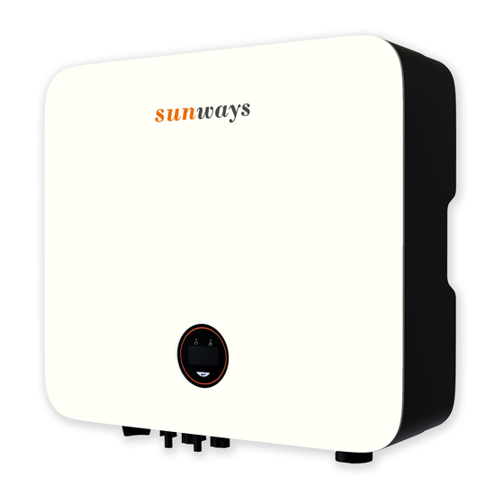
Summary of Contents for Sunways STS-3K
- Page 1 Grid-connected PV Inverter S i n g l e P h a s e D u a l M P PT User Manual STS-3K/3.6K/4.2K/4.6K/5K/6KTL Sunways Technologies Co., Ltd.
-
Page 2: Table Of Contents
CONTENTS 1. Preface ........................5 1.1 Overview ......................5 1.2 Target Groups ....................5 2. Safety Instructions ....................5 2.1 Safety Notes ....................5 2.2 Statement ......................5 2.3 Important Safety Matters ................6 2.4 Symbols Explanation ..................7 3. Product Description .....................9 3.1 Basic Features ....................9 3.2 Physical Layout ...................10 3.3 Display Interface ..................12 3.4 Packing List ....................13 4. -
Page 3: Safety Instructions
2.1.8 When exposed to sunlight, the PV array generates dangerous high DC voltage. Please operate according to our instructions, or it will result in danger to life. 2.2 Statement Sunways Technologies Co., Ltd. has the right not to undertake quality assurance in any of the following circumstances:... -
Page 4: Important Safety Matters
2.4 Symbols Explanation 2.2.1 Damages caused by improper transportation. 2.2.2 Damages caused by incorrect storage, installation or use. This chapter mainly elaborates the symbols displayed on the inverter, nameplate and packing 2.2.3 Damages caused by installation and use of equipment by non-professionals or untrained box. -
Page 5: Product Description
3.1.3 Applicable grid type The applicable grid types for the Sunways STS 3~6kW series are TN-S, TN-C, TN-C-S and TT. When applied to the TT grid, the voltage of N to PE should be less than 30V. For more details Stacked layers. - Page 6 3.2 Physical Layout 3.2.3 Inverter bottom view: 3.2.1 Inverter front view: 410mm Logo DC Switch (Optional) Back Rail DC Input Terminal Com1 Port Com2 Port (Optional) Display Figure 3-4 Bottom view 3.2.4 Inverter back view: Figure 3-2 Front view 3.2.2 Inverter side view: Back Rail 120mm Name...
-
Page 7: Installation
4.1 Location Slow flashing Inverter powered on, waiting for the grid connection. Power The Sunways STS 3~6kW series inverter is designed with IP65 protection enclosure for indoor Indicator Quick flashing Inverter detected grid power and entered self-test status. and outdoor installations. When selecting an inverter installation location, the following factors should be considered: Normal, grid-connected and power generated. - Page 8 4.2 Mounting 4.2.1 Wall bracket installation Dimensions of wall bracket, see Figure 4-4: Figure 4-1 Recommended installation location 220mm 16mm Warning Do not put flammable and explosive articles around the inverter. 110mm 110mm 4.1.2 The requirements for inverter installation spacing are shown in Figure 4-2: 10mm 300mm 300mm...
-
Page 9: Electrical Connection
Do not use other brands or other types of terminals other than the terminals in Attention the accessory package. Sunways has the right to refuse all damages caused by the mixed-use of terminals. Moisture and dust can damage the inverter, ensure the cable gland is securely Attention tightened during installation. - Page 10 8) Seal the unused PV terminals with the terminal caps. 4.3.2 Connection of AC output The Sunways STS 3~6kW series single phase inverter operates with grid voltage and frequency of 220/230V and 50/60Hz, respectively. This inverter includes an integrated residual current device (RCD) .
- Page 11 The recommended cable and AC switch for the Sunways STS 3~6kW series single phase inverter are shown in the following table: Model STS-3KTL STS-3.6KTL STS-4.2KTL STS-4.6KTL STS-5KTL STS-6KTL Cable A ll e n Ke y Breaker Figure 4-16 An AC breaker must be connected on the AC side of the inverter.
-
Page 12: Monitoring Device Installation
4.4 Monitoring Device Installation Port 1 Port 2 Port 3 Note Sunways STS 3~6kW series single phase inverter supports WiFi, GPRS, LAN and RS485 CT Port RS485 Ports DRED Port communication. Plug the WiFi, LAN or GPRS module into the COM1 port in the bottom of inverter (as shown in Figure 4-20). - Page 13 0.75-1.5mm² and an outer diameter of 5mm-10mm. series inverter. RS485 cable requirements: Shielded twisted-pair cable or shielded twisted NULL 3.The color of CT is only identified by Sunways. Ethernet cable. RS485 A 1.Export limitation & control/RS485/DRED version with this port.
-
Page 14: System Layout Of Units Without Integrated Dc Switch
Insulator ring Inverter 20-25mm Grid DC Switch Port 1 DC INPUT AC OUTPUT Port 2 AC Breaker 20-25mm Port 3 Screw cap Metal plate Sealing ring 3/6pin connector To grounding electrode Figure 4-23 Figure 4-25 5. Start and Stop Start the Inverter When starting the inverter, follow these steps: 1) Turn on the AC breaker first (close the AC circuit breaker). -
Page 15: Display Operation
6. General Operation 6.2 Auto-Test This function is disabled by default, and will be only functional in the safety code of Italy. Short 6.1 Display Operation press the button several times until “Auto Test CEI 0-21” displays on the screen, press and When the inverter is turned on, the following interfaces will be displayed on the OLED display, hold the button 3 seconds to activate “Auto Test”. -
Page 16: Ac Output Boost For Sts-5Ktl Inverter
Australia. Check the local DNSPs or authorities if they allow AC output more than 5kVA. Sunways STS 3~6kW series single phase inverter is designed in accordance with grid operation standards, and conform to the requirements of safety and EMC. The inverter had passed a 1. -
Page 17: Maintenance
Attention Rated Output Power (W) 3000 3600 4200 4600 5000 6000 Never arbitrarily replace any internal components. For any maintenance support, please contact Sunways. Otherwise, Sunways ② ④ Max. Output Power (W) 3300 3960 4600 4600 5500 6600 shall not be held liable for any damage caused. - Page 18 < 25 Display OLED & LED Address: No. 1, Second Road, Green Industrial Zone, Chongshou Town, Communication RS485/WiFi/GPRS/LAN (Optional) Cixi City, ZheJiang Province, PEOPLE’S REPUBLIC OF CHINA NB/T32004、IEC62109、IEC62116、VDE4105、VDE0126、UTE C15-712-1、 Website: www.sunways-tech.com Compliance AS4777、C10/11、CEI 0-21、RD1699、NBR16149、IEC61727、IEC60068、 IEC61683、EN50549、EN61000 Service Mail: service@sunways-tech.com Hotline: +86 400-9922-958...


Need help?
Do you have a question about the STS-3K and is the answer not in the manual?
Questions and answers