John Wood CT-199 Installation Manual And Owner's Manual
Commercial condensing tankless water heater
Hide thumbs
Also See for CT-199:
- Installation manual and owner's manual (64 pages) ,
- Installation manual and owner's manual (64 pages)
Table of Contents
Advertisement
Quick Links
Commercial Condensing Tankless Water Heater
Installation Manual and Owner's Guide
R
ANSI Z21.10.3 ・ CSA 4.3
Models
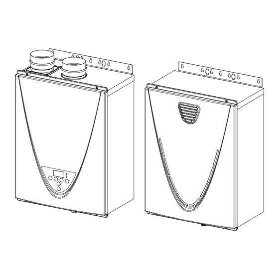
CT-199 Indoor
Gas Tankless Water Heater
Suitable for combination potable water heating and
space heating. Please refer to local codes for space-
heating compliance.
FEATURING
• ENDLESS HOT WATER
• ON-DEMAND USAGE
• COMPACT, SPACE SAVING
• ENERGY CONSERVATION
• COMPUTERIZED SAFETY
• NO PILOT LIGHT
• Complies with SCAQMD Rule
1146.2 for natural gas Low NOx
Emissions of 14 ng/J or 20 ppm.
• EASY-LINK SYSTEM
• MULTI-UNIT SYSTEM
Keep this manual near the water heater for future reference whenever maintenance, adjustment, or
service is required.
D
R
CT-199 Outdoor
(USA only)
TM
If the information in these
instructions is not followed
exactly, a fire or explosion may
result causing property damage,
WARNING
personal injury or death.
- Do not store or use gasoline or other
flammable vapors and liquids in the vicinity
of this or any other appliance.
- WHAT TO DO IF YOU SMELL GAS
• Do not try to light any appliance.
• Do not touch any electric switch; do not
use any phone in your building.
• Immediately call your gas supplier from
a neighbor's phone. Follow the gas
supplier's instructions.
• If you cannot reach your gas supplier, call
the fire department.
- Installation and service must be performed
by a qualified installer, service agency or the
gas supplier.
If you have any questions, please
call or write to:
In the United States
500 Tennessee Waltz Parkway
Ashland City, TN 37015
Toll Free: 1-877-737-2840
In Canada
599 Hill Street West
Fergus, ON N1M 2X1
1-888-479-8324
Advertisement
Table of Contents

Subscribe to Our Youtube Channel
Related Manuals for John Wood CT-199


Summary of Contents for John Wood CT-199
- Page 1 Installation Manual and Owner’s Guide ANSI Z21.10.3 ・ CSA 4.3 If the information in these Models instructions is not followed exactly, a fire or explosion may CT-199 Indoor CT-199 Outdoor result causing property damage, WARNING (USA only) personal injury or death.
-
Page 2: Table Of Contents
Contents CONTENTS Installation Manual Owner's Guide SPECIFICATIONS ..........4 OPERATING SAFETY ........46 INTRODUCTION ..........5 NORMAL OPERATION ........48 SAFETY GUIDELINES........6 BUILT-IN CONTROLLER SAFETY DEFINITION ........6 AND REMOTE CONTROLLER ....48 GENERAL ............6 GENERAL ............48 INSTALLATION ..........7 OUTLET WATER TEMPERATURE GENERAL ............7 SETTING .............49 CLEARANCES ..........9 TEMPERATURE TABLE OF CONTROLLER .49 INCLUDED ACCESSORIES ......9... -
Page 3: Installation Manual
Installation Manual Installation Manual Installation Manual CONGRATULATIONS Congratulations and thank you for choosing our tankless water heater. Before use, we recommend that you read through this installation manual carefully. Keep this manual for future reference. If you need an additional manual, contact the manufacturer or your local distributor. -
Page 4: Specifications
Installation Manual Specifications SPECIFICATIONS CT-199 Indoor CT-199 Outdoor Model (AT-H3C-DV) (AT-H3C-OS) Natural Gas Input Min.: 15,000 BTU/h (Operating Range) Max.: 199,000 Propane Input Min.: 13,000 BTU/h (Operating Range) Max.: 199,000 Gas Connection 3/4" NPT 3/4" NPT Water Connections Water Pressure* psi (MPa) 15 - 150 (0.1 - 1) -
Page 5: Introduction
• These high efficiency models have a built-in secondary heat exchanger that absorbs latent heat from the exhaust gas. • The CT-199 Indoor model is only to be installed indoors. The CT-199 Outdoor model is only to be installed outdoors. -
Page 6: Safety Guidelines
Installation Manual Safety Guidelines SAFETY GUIDELINES SAFETY DEFINITION Indicates an imminently hazardous situation which, if not avoided, will result in death or serious injury. DANGER Indicates an imminently hazardous situation which, if not avoided, could result in death or serious injury. WARNING Indicates an imminently hazardous situation which, if not avoided, could result in minor or moderate injury. -
Page 7: Installation
Installation Manual Installation INSTALLATION GENERAL 1. Follow all local codes, or in the absence of local codes, follow the current edition of the National Fuel Gas Code: ANSI Z223.1/NFPA 54 in the USA or B149.1 Natural Gas, Propane Installation Code in Canada. 2. - Page 8 Installation Manual Installation • Installation and service must be performed by a qualified installer (for example, a licensed plumber or gas fitter). Otherwise, the warranty will be void. • The installer (licensed professional) is responsible for the correct installation of the water heater and for compliance with all national, state/provincial, and local codes.
-
Page 9: Clearances
Bottom Model Bottom Front Back Sides 12 in 12 in 4 in* 0.5 in 3 in CT-199 Indoor (305 mm) (305 mm) (102 mm) (13 mm) (76 mm) 36 in 12 in 24 in 0.5 in 3 in CT-199 Outdoor... - Page 10 Installation Manual Installation 2. Pipe cover: 1. Temperature remote controller: 100112718 (TH-PC03) 100112572 (TM-RE40) The pipe cover protects The temperature remote controllers have the plumbing pipes to three functions. It allows the output the water heater from temperature from the water heater to be unexpected adjustments.
-
Page 11: Warning For Installations
Installation Manual Installation WARNING FOR INSTALLATIONS FOR YOUR SAFETY, READ BEFORE INSTALLATION: Do not install the heater where water, debris or Do not have the vent terminal pointing toward flammable vapors may get into the flue terminal. any opening into a building. Do not locate your This may cause damage to the heater and void the heater in a pit or location where gas and water warranty. -
Page 12: High-Altitude Installations
ON 1 2 3 4 5 6 ON 1 2 3 4 5 6 ON 1 2 3 4 5 6 ON 1 2 3 4 5 6 CT-199 (Lower bank of No. 2 : OFF No. 2 : OFF No. -
Page 13: Venting Instructions
Installation Manual Installation VENTING INSTRUCTIONS • Improper venting of this appliance can result in excessive levels of carbon monoxide which can result in severe personal injury or death. • Improper installation can cause nausea or asphyxiation, severe injury or death from carbon monoxide and flue gases poisoning. -
Page 14: Vent Termination Clearances
Installation Manual Installation -Vent termination clearances- Inside Legend: corner detail = Vent terminal = Air supply inlet = Area where terminal is not permi�ed 15 � Fixed Operable closed Fixed closed Operable Regulator vent outlet In the event no regulator is present, H and I can be disregarded Canada Installations US Installations... -
Page 15: Clearances For Sidewall Terminations
Installation Manual Installation -Clearances for sidewall terminations- Improper installation can result in carbon monoxide poisoning or death. Follow all local and national codes in regards to proper termination clearances. In the absence of such codes, the clearances below can be used as guidelines. Local codes supersede these WARNING guidelines. -
Page 16: Clearances For Rooftop Terminations
Installation Manual Installation -Clearances for rooftop terminations- Follow all local and national codes in regards to proper termination clearances. In the absence of such codes, the clearances below must be met. Local codes supersede these clearances. Failure to observe this warning may result in severe personal injury or death. WARNING Canadian requirements differ from the guidelines in this section. -
Page 17: Combustion Air Supply
Installation Manual Installation -Combustion air supply- This gas water heater requires an adequate source of clean air for combustion and ventilation. Without sufficient air, your water heater may not operate properly and may emit excessive and abnormal amounts of carbon monoxide which may result in WARNING carbon monoxide poisoning or death. - Page 18 Installation Manual Installation Your water heater’s BTU/h rating is on the rating plate. The BTU/h ratings should be on the other appliances’ rating plates. If you have trouble determining the BTU/h ratings, contact the manufacturer or have a qualified person determine the ventilation requirements. : If you are replacing your old water heater with one that has a higher BTU/h rating, the amount of NOTICE ventilation required may be greater.
- Page 19 Installation Manual Installation Determine type of ventilation There are several types of ventilation that can be used. The various options are listed below. See also the illustrations on the next page. 1. Direct to outdoors 2. Vertical ducts 3. Horizontal ducts 4.
- Page 20 Installation Manual Installation Combustion air supply options Gable vent to outdoors Install above insulation 12” (305 mm) Outlet air to Confined maximum attic 1 in (6.5 cm Space per 4,000 btu/h Two permanent Openings Confined Alternate Inlet air from 1 in (6.5 cm Space Air Inlet...
-
Page 21: Exhaust Vent (Abs,Pvc,Cpvc, Or Polypropylene Vent)
Installation Manual Installation -Exhaust vent (ABS, PVC, CPVC, or polypropylene vent)- The Indoor models can be vented with ABS, PVC, CPVC, or polypropylene (temperature rated up to 149 °F). Vent material certified to ULC S636 standards is recommended in the USA. In Canada, plastic venting must be certified to ULC S636 standards. -
Page 22: Dip Switch Settings For Vent Length (Abs,Pvc,Cpvc, Or Polypropylene Vent)
ON 1 2 3 4 5 6 7 8 ON 1 2 3 4 5 6 7 8 ON 1 2 3 4 5 6 7 8 ON 1 2 3 4 5 6 7 8 CT-199 (Upper bank No. 3 : OFF No. 3 : O N No. - Page 23 ON 1 2 3 4 5 6 7 8 ON 1 2 3 4 5 6 7 8 ON 1 2 3 4 5 6 7 8 ON 1 2 3 4 5 6 7 8 CT-199 (Upper bank No. 3 : OFF No. 3 : OFF No.
- Page 24 Installation Manual Installation 3" vent connection for PVC/CPVC venting only 4" vent connection for PVC/CPVC venting only 4" straight pipe 3" x 4" increaser 3" street elbow 3" straight pipe with bird screen 3" straight pipe 3" street elbow no more than 12" with bird screen (305 mm) Exhaust vent collar with...
-
Page 25: Exhaust Vent (Stainless Steel Vent)
Installation Manual Installation -Exhaust vent (Stainless steel vent)- This is a Category IV appliance and must be vented accordingly. The vent system must be sealed airtight. All seams and joints without gaskets must be sealed with high heat resistant silicone sealant or UL listed aluminum adhesive tape having a minimum temperature rating of 160 °F (71 °C). - Page 26 Installation Manual Installation <How to remove 3" PVC adapter from the intake/exhaust collar> 3" adapter* 3" adapter* *Remove the 3" adapter when using metal vent. Exhaust vent Intake vent collar collar (Female) (Female) Screw 4" vent connection for direct-vent installation 4"...
-
Page 27: Common Venting System
Centrotherm's vent line. • 240HX3/340HX3/540HX3 models do not have Easy-Link or Multi-Unit capability. Allowable models for common-venting 240H, 340H, 540H, 540P, CT-199, 240HX3, 340HX3, 540HX3 Only the models listed in the table above can be common-vented together. Other models cannot be common-vented. - Page 28 DO NOT 6 in 50 ft (15.2 m adjust the other DIP 25 ft (7.6 m) switches. CT-199 Indoor 20 ft (6.1 m) (Refer to page 22 for (Upper bank of the location of the DIP switches) 100 ft (30.5 m) ON 1 2 3 4 5 6 7 8 DIP switches.)
-
Page 29: Gas Supply And Gas Pipe Sizing
Installation Manual Installation GAS SUPPLY AND GAS PIPE SIZING -General- • Do not use this water heater with any gas other than the one listed on the rating plate. • Ensure that any and all gas regulators used are operating properly and providing gas pressures within the specified range shown below. -
Page 30: Natural Gas Supply Piping
0.60 Specific Gravity with a Pressure Drop of 0.5" W.C.). Based on Energy Content of 1,000 BTU/Cubic ft: The water heater requires 199 Cubic ft/hr for the CT-199 model. The following tables are from NFPA 54. Unit: Cubic feet per hour... -
Page 31: Water Connections
• The pressure relief valve must conform to ANSI Z21.22/CSA 4.4 and installation must follow local codes. • The discharge capacity must be at least 199,000 BTU/h for the CT-199 model. • The pressure relief valve needs to be rated for a maximum of 150 psi (1 MPa). -
Page 32: Condensate Drain
Installation Manual Installation CONDENSATE DRAIN This high efficiency water heater produces acidic condensate that must be properly drained per local codes. The water heater does not have a built-in neutralizer to raise the pH level. A neutralizer is available from the water heater manufacturer, if needed. Follow the instructions in this section in order to install the condensate drain line. - Page 33 Installation Manual Installation Installation Installation without neutralizer with neutralizer 1/2" MPT 1/2" MPT condensate condensate connection 1/2" connection Condensate 1/2" Condensate drain tube* drain tube* 1/2" MPT x 3/8" FPT (Included with Neutralizer accessory) 1/2" Overflow bypass* Condensate (1/2" Condensate Neutralizer cartridge (Included drain tube* drain tube)
-
Page 34: Electrical Connections
Installation Manual Installation ELECTRICAL CONNECTIONS • Follow the electrical code requirements of the local authority having jurisdiction. In the absence of such requirements, follow the current edition of the National Electrical Code ANSI/NFPA 70 in the U.S. or the current edition of CSA C22.1 Canadian Electrical Code Part 1 in Canada. -
Page 35: Temperature Remote Controller
Installation Manual Installation TEMPERATURE REMOTE CONTROLLER -Included accessories-Outdoor model only The remote control is an optional accessory that can be installed in a hall, closet, etc., to allow for • temperature adjustment without having to go to the heater. When installed, the remote will take priority over the built-in controller of indoor models. •... - Page 36 Installation Manual Installation 4. Tighten the two Fork terminals beneath the two Remote controller terminal screws on the back of the main body. (Fig. D-1) 5. Cut out the inlet for the remote controller cable from the bottom of the main body. (Fig. D-2) 6.
-
Page 37: Easy-Link System
• When the 710 and CT-199 are connected together in an Easy-Link System, change DIP switch No. 6 on the lower bank of DIP switches on the CT-199 model computer board to the "ON" position. (See the following page for detail.) •... - Page 38 No. 6 ON • To change the DIP switch settings for the Easy-Link System, locate the lower bank of DIP switches at the bottom left of the computer board of CT-199. • DO NOT adjust any other DIP switches .
-
Page 39: Multi-Unit System
Installation MULTI-UNIT SYSTEM Multiple CT-199 models can be combined for a Multi-Unit System, along with the multi-unit controller (Part 100112691 (TM-MC02)). The multi-unit controller can control from 2 units to 20 units for commercial or residential applications. For a 20-unit system, the computer can modulate between the usages of 13,000 BTU/h (Propane) or 15,000 BTU/h (Natural gas) to 3.98 Million BTU/h. -
Page 40: Applications
Installation Manual Applications APPLICATIONS -Recirculation- When installing a recirculation pump, care must be taken to properly size the pump for the application. Siz- ing must be performed by the installing contractor or engineer. Below are requirements that need to be followed when sizing: •... -
Page 41: Domestic And Space Heating
Installation Manual Applications -Domestic and Space Heating- • This water heater is suitable for combination water (potable) heating & space heating and not suitable for space heating applications only. • This water heater shall not be connected to any heating system or component(s) previously used with non-potable water where any chemicals were added to the water heating appliances. - Page 42 Installation Manual Applications Below is a suggested piping layout. The installer must properly install the system per manufacturers in- structions and local codes. LEGEND THERMOSTATIC MIXING VALVE TEMPERED HOT WATER TO FIXTURE PRESSURE RELIEF VALVE CIRCULATION PUMP BALL VALVE CHECK VALVE COLD BUILDING RETURN...
-
Page 43: Dual-Purpose Water Heating Of The State Of Massachusetts
Installation Manual Applications -Dual Purpose Water Heating for the State of Massachusetts- Diagrammatic layout of radiant heating and domestic water heater. All water piping should be insulated in accordance with 780 CMR (Massachusetts energy code) 3-inch gas exhaust vent (Discharge must Cold water supply Automatic tempering device comply with local and... -
Page 44: Initial Operation
Installation Manual Initial operation INITIAL OPERATION FOR YOUR SAFETY, READ BEFORE OPERATING • Check the GAS and WATER CONNECTIONS for leaks before firing unit for the first time. • Open the main gas supply valve to the unit using only your hand to avoid any spark. Never use tools. -
Page 45: Owner's Guide
Owner's Guide Operating Safety Owner's Guide Owner's Guide CONGRATULATIONS Congratulations and thank you for choosing our tankless water heater. Before use, we recommend that you read through this owner's guide carefully. Keep this manual for future reference. If you need an additional manual, contact the manufacturer or your local distributor. -
Page 46: Operating Safety
Owner's Guide Operating Safety OPERATING SAFETY FOR YOUR SAFETY READ BEFORE OPERATING If you do not follow these instructions exactly, a fire or explosion may result WARNING: causing property damage, personal injury or loss of life. A. This appliance does not have a pilot. It is equipped with an ignition device which automatically lights the burner. - Page 47 Owner's Guide Operating Safety DANGER Vapors from flammable liquids will explode and catch fire causing death or severe burns. Do not use or store flammable products such as gasoline, solvents or adhesives in the same room or area near the water heater. Do not install water heater where flammable products will be stored or used unless the main burner is at least 18”...
-
Page 48: Normal Operation
Owner's Guide Normal Operation NORMAL OPERATION BUILT-IN CONTROLLER AND REMOTE CONTROLLER The illustration below shows an example of the controllers. The exact display may differ from examples. Built-in controller Remote controller Display for Temperature "INFO" Button When the STAND BY LED is ON, the hot water temperature will be Each time the button is pressed, displayed. -
Page 49: Outlet Water Temperature Setting
Owner's Guide Normal Operation OUTLET WATER TEMPERATURE SETTING -Set temperature Screen on the controller Operation Built-in controller Remote controller Turn on the 120 VAC power supply to the unit (the water heater or the multi-unit controller). Press the "ON/OFF" button on the controller in order to turn the controller on. -
Page 50: Additional Features
Owner's Guide Normal Operation ADDITIONAL FEATURES -Information mode- You can get some information about the water heater condition by pressing the "INFO" button. For more information, follow the procedures below: Screen on the controller INFO Operation Button Built-in controller Remote controller Inlet water temperature will be Inlet water temperature 1st. -
Page 51: Temperature Settings On The Pcb
• CT-199 Indoor briefly fires on for about 3 seconds to provide freeze protection around the heat exchanger drum - Automatic firing system. Once 5 minutes have elapsed since the CT-199 Indoor previous firing operation, the computer will continually check the temperature of the exhaust thermistor. -
Page 52: Flow
Normal Operation FLOW • The flow rate through the water heater is limited to a maximum of 10.0 GPM (38 L/min) for the CT-199. • The temperature setting, along with the supply temperature of the water will determine the flow rate output of the unit. -
Page 53: Inlet Water Filter Cleaning
Owner's Guide Normal Operation 5. With all gas burning equipment off, take a reading of the static gas pressure and make MAX button a note of it. MIN button 6. Measure gas supply pressure at maximum heater operation: Open hot water faucets to create maximum flow. -
Page 54: Troubleshooting
Owner's Guide Troubleshooting TROUBLESHOOTING GENERAL PROBLEM SOLUTIONS It takes a long time to • The time it takes to deliver hot water from the water heater to your fixtures get hot water at the depends on the length of piping between the two. The longer the distance fixtures. -
Page 55: Error Codes
Owner's Guide Troubleshooting PROBLEM SOLUTIONS Controller does not • Make sure the unit is supplied with power. display anything when • Make sure the connection to the unit is correct. (pp. 35 and 36) the power button is NOTICE: turned on. When the unit has not operated for five minutes or more, the display of the controllers turns off to conserve energy. -
Page 56: Single Unit Installation
Owner's Guide Troubleshooting -Single unit Installation- Example: If your unit has a “321” error code (which signifies an inlet thermistor failure) • Indicator on the built-in controller or remote controller : “321” will be displayed on the screen. Error code •... -
Page 57: Fault Analysis Error Code
Owner's Guide Troubleshooting Outdoor model installation Indicator on the remote controller of Parent unit (If it is installed): "321" and "2" will alternately flash on the display. No. 2 Unit: The green Unit #1 Unit #2 Unit #3 Unit #4 LED on the computer PARENT CHILD... - Page 58 Owner's Guide Troubleshooting Malfunction Green Diagnosis Remote description 331* Outlet thermistor Flashes failure • Check for connection/breakage of wires and/or debris on thermistor 341* Exhaust thermistor (Part #407, 408, 411, 715). Flashes failure (Indoor model only) 391* Air-fuel ratio rod •...
-
Page 59: Components Diagram
Owner's Guide Components Diagram COMPONENTS DIAGRAM Case assembly Indoor model Outdoor model Built-in controller Indoor model Surge box assembly Temperature remote controller Page... - Page 60 Owner's Guide Components Diagram Computer board assembly 707 722 Wiring diagram CT-199 Outdoor Only Heater Heater Igniter rod Heater Heater Thermostat CT-199 Indoor Only Ground Heater Surge Flame rod limit Heater switch Heater Ground BL BL AFR rod O.H.C.F Propor- �onal...
- Page 61 Owner's Guide Components Diagram Burner assembly Burner assembly 109 111 Manifold assembly Page...
- Page 62 Owner's Guide Components Diagram Water Way assembly Bypass section Water outlet section Water inlet section Page...
-
Page 63: Parts List
Owner's Guide Parts List PARTS LIST Item Item Description Part # Description Part # 001 Case assembly for Indoor model Gas inlet ring 100074526 for Outdoor model Surge box plate 002 Front cover for Indoor 100074665 O-ring P18 NBR (Black) 100074533 for Outdoor 100074666... -
Page 64: Output Temperature Chart
Owner's Guide Output Temperature Chart Item Item Description Part # Description Part # Stainless heat exchanger out pipe 100074690 Flame rod wire 100074652 Header connection 100074691 Igniter assembly 100074640 Drain port 100074692 713 Switch wire with thermostat for Indoor 100342431 Thermistor fixing plate 100074291 Switch wire with thermostat for Outdoor...
Need help?
Do you have a question about the CT-199 and is the answer not in the manual?
Questions and answers