Table of Contents
Advertisement
Quick Links
Advertisement
Table of Contents

Subscribe to Our Youtube Channel
Related Manuals for Humboldt HM-5810


Summary of Contents for Humboldt HM-5810
- Page 1 HM-5810.3F product manual 09.22 Automated Pressure Controller...
-
Page 3: Table Of Contents
Test Setup Motor Speed Unit Test Setup Stress Control Unit How to Fill Hydraulic Pistons Preferences – Specimen Parameters Tab 18 Deairing Line from HM-5810 to Cell Specimen Height Pressurizing Specimen Diameter Permeability Setup Preferences – Storage Tab Filling the Triaxial Cell... -
Page 4: Quick Start Guide
The Fuse Com- partment is located between the electrical cord inlet and the Power Switch. The HM-5810 uses a 10 amp fuse. To begin operation, attach the supplied electrical cord, plug it in and press the Power Switch. -
Page 5: Instrumentation Connections And Setup
Instrumentation Connections and Setup HM-5810 Rear Instrumentation Panel Above is a photo of the rear instrumentation panel of the HM-5810. Network (1) Ethernet input for connecting machine to a local area net- work (LAN) and/or the internet. USB Power (2) The USB Power port is used for powering a wireless access appliance for those who want to use a wireless LAN setup. - Page 6 Below are photos of an instrumentation input and the in- strumentation plug. Install the plugs into the inputs by lining up the guide at the bottom of the plug with the slot at the bottom of the input. Instrumentation Input Instrumentation Plug Once you have installed the instrumentation into the correct inputs, your rear panel should look like this if you are using...
-
Page 7: Initial Set-Up
Third-party instrumentation, which is compatible, can also be used with the HM-5810. If you plan to use third-party load cells and/or transducers, please refer to the Equipment Setup section of this manual, page 31 for instructions. -
Page 8: Initial Set-Up - Calibration
Navigate to the bottom of this drop-down menu and click on System Settings (1). You will see the following screen. Initial Set Up — Calibration Click on the Calibration tab in the top left corner (2). You will see the following screen. -
Page 9: Calibration Input Screen
The Calibration Input Screen (above) is used to monitor and calibrate instrumentation and assign them to specific chan- nels of the HM-5810. The Calibration Input Screen provides a summary of the calibration status of each channel. At this time, verify the calibration information. -
Page 10: Units
(1). The screen above shows a typical cell pressure calibration setup. In this example, the HM-5810 has been set up for a standard Consolidated Drained or Undrained Triaxial setup. Input 1 is set up to read Cell Pressure of 0.0-200.0 psi; Input 2... - Page 11 is set up to read Base Pressure of 0.0-200.0 psi, and Input 3 is set up to read Top Pressure from 0.0-200.0 psi.` Now, we need to calibrate the Cell Volume. To get to the volumes calibration page you need to push the Volumes button at the bottom of the screen (1).
- Page 12 Ensure that the calibration limit is set to 250 cm (1). Select the Per FS Output radio button (1). Ensure that the cell piston has been fully moved to the down position, you will then be prompted to reset encoder, select YES (1).
-
Page 13: Export Calibration Via Usb
This thumbdrive will contain the calibration data for the extra instrumentation. To use this calibration information, it is rec- ommended to first export all your HM-5810’s calibration data to the thumbdrive and then download the additional calibra- tion data you need for your additional test setups (2). -
Page 14: Initial Set Up - Date/Time
Initial Set Up — Date and Time Click on the Date/Time tab (1). You will see the following screen. Date (1) Set the month, day, year, and date display format. Time (2) Set the hours, minutes, seconds, and am/pm. Clock Style (3) Select a clock view, either a 24-hour or 12-hour clock, as well as the option to show seconds or not. -
Page 15: Initial Set Up - Display
Initial Set Up — Display To set up Date and Time settings, return to the System Settings screen and click on the Date/Time Panel. (1) Click on the Display tab (1). You will see the following screen. Brightness (1) Slide the gray bar to the left or right to adjust brightness. Dim Display (2) The backlight of the display will automatically dim to save power. -
Page 16: Turn Display Off
Turn Display Off (3) The display will automatically turn off to save power. Click the yellow box to change the number of minutes before the display powers off. Initial Set Up — Preferences This screen is accessed by clicking on the “Preferences” button. -
Page 17: Logger Id
Logger ID (1) Each machine that is connected to your network requires a unique Logger ID. These numbers can be assigned any number between 1-245. In most cases, if you are setting up a new machine it has been given the Logger ID 1. This would show in the Logger ID field. -
Page 18: Motor Speed Unit
Motor Speed Unit (2) Click on the desired units you want to use for motor control (in/min or mm/min). Stress Control Unit (3) Click on the desired units you want to use for stress control (LBF, KN, KSF OR KPA). Preferences –... -
Page 19: Test Storage Limit
Test Storage Limit (1) This field allows you to set the number of previously run tests to be available on the “Previous Tests” screen. This number can be between 10-50. Recycled Tests (2) This refers to previously run tests that are not displayed in the “Previous Tests”... - Page 20 A password is required to access the Network Settings. That password is: 27604.
-
Page 21: Network Settings Screen
Network Settings Screen The screen above is the Network Settings screen, it provides information on your IP information and network status. DHCP (1) Check this box to enable/disable the Dynamic Host Configu- ration Protocol (DHCP). If enabled, your machine will pick up IP information from your router. -
Page 22: System Information
This indicates the current status of how much available memory is being used by the machine Factory Screen (6) This is for Humboldt use only. Export Log File (7) This button exports a log file from the machine to a USB thumb drive. -
Page 23: Initial Set Up -Contact
This will provide us with the necessary in- formation to assist you and you will be added to the next position in the support cue. You can also email Humboldt Support at support@hum- boldtmfg.com or Humboldt Service at service@humboldtm- fg.com. Please include contact information and a detailed... -
Page 24: Initial Set Up - Update
USB drive. Firmware updates are available for download from our website at: https://www.humboldtmfg.com/sup- port/software.php. Once on the website page, click on the Elite Series Firmware tab. You will see a list of Humboldt Elite Series machines. Click on the HM-5810 Current Version link and the firmware... -
Page 25: Check For Update
Check for Update (2) If your HM-5810 is connected to the internet, you can have the machine check automatically for updates, which can be found under System Settings – Preferences button. How often the machine checks for updates can be customized under Preferences. -
Page 26: Operation From A Computer And Next
Operation from a Computer and NEXT Software This manual covers the setup and operation of the HM-5810.3F Controller in Stand-alone Mode only. For information on operating your load frame with Humboldt’s NEXT Software and a computer, please refer to the... -
Page 28: Installation And Equipment Setup
The Fuse Compartment is located between the electrical cord inlet and the Power Switch. The HM-5810 uses a 10 amp fuse. To begin operation, attach the supplied electrical cord, plug it in and press the Power Switch. -
Page 29: Network
Above is a photo of the rear instrumentation panel of the HM-5810. Network (1) Ethernet input for connecting machine to a local area network (LAN) and/or the internet. USB Power (2) The USB Power port is used for powering a wireless access appliance for those who want to use a wireless LAN setup. -
Page 30: Instrumentation Setup
Instrumentation Setup On the next page are examples of typical instrumentation setups for different tests the HM-5810 is capable of running. When you receive your unit, if you purchased instrumentation from Humboldt, your instrumentation will be attached to the machine for shipping. Please use the photographs on the following page as a guide for setting up the instrumentation for testing. -
Page 31: Third-Party Instrumentation
Third-Party Instrumentation Third-party load cells/transducers, which are compatible, can also be used with the HM-5810. Compatible units must work with an excitation voltage of 8.25 volts and produce an output of 0-5 volts. Prior to use, all third-party in- strumentation must be configured and calibrated. If you are using third-party cables for load cells/transducers connections, make sure they are wired to be compatible with the HM-5810, see illustration below. - Page 32 To begin a calibration, navigate to the Calibration section by clicking the Menu icon in the top left corner of the screen (1). When you click on this button, you will see a drop-down menu appear, see below. Navigate to the bottom of this drop-down menu and click on System Settings (2).
-
Page 33: Calibration Input Screen
The Calibration Input Screen (above) is used to monitor and calibrate instrumentation and assign them to specific channels of the HM-5810. The Calibration Input Screen provides a summary of the calibration status of each channel. At this time, verify the calibration information. -
Page 34: Units
Each channel has a “Limits On” check box (1). Use the Limits On to keep the machine from exceeding the sensor limits of the instrumen- tation. By selecting this option, before the test can exceed the limits of the sensors, all tests will stop running and the motor will stop to avoid damaging connected instrumentation. -
Page 35: Performing A New Calibration
Performing a New Calibration The first step in calibrating instrumentation to an input is to remove any calibration that is already being used for that input. To do this, Press the Export Calibration Button (4) (see next page) to select calibrations to export via USB. - Page 36 Once your calibrations have been saved, you will see a pop up screen that says: Calibration Export Successful. To begin to remove existing calibrations, click on the trash can icon (5) to begin to erase the Input calibrations you wish to recalibrate. When you press the trash can icon, this screen will appear.
- Page 37 The calibra- tion process involves plugging the instrumentation into the HM-5810 while placing the instrumentation into the certified calibration device, which provides a specific set load or displacement.
- Page 38 Upon filling in the password, you will see this screen, Tab 1 Sensor Details of the Calibration settings. On Tab 1, the Sensor Type (1) will default to Volume. For Capacity (2), fill in the maximum capacity of the sensor and choose either lbf or kN.
- Page 39 Once this is complete, click on the Right Arrow (4), in the bottom right-hand corner of the screen to save these settings. You will be taken to Tab 2, Limits. On Tab 2, in the Calibration Limit field (1), enter the maximum calibrated limit of the sensor.
- Page 40 If you choose Multi-Point (Not recommended for encoder counts when Curve and click on the Right Arrow in the calibrating the volume control) bottom right-hand corner of the screen, you will be taken to Tab 3. On Tab 3 you will be able to set the number of points you want to use for your calibration.
- Page 41 Connect the instrumentation sensor connected to a calibrated pres- sure control device, and connect the instrumentation plug to the appropriate channel Input on the back of the HM-5810. You will set the “0” point at 0 with no pressure applied to the sensor. A “5” point calibration will be set with the maximum load capacity of the sensor applied.
- Page 42 On Tab 4, you will be asked to name the calibrated Input. If a user de- fined name is not chosen the machine will save the calibration using a default name based on the sensor type and channel input number. The screen will provide a default name, but you can name the In- put anything you’d like.
-
Page 44: Test Setup
Test Setup To begin a new test, first, you will need to fill your deairing tank. To begin set all knobs into the Off position, see photo below. Then: 1. In the Deairing Tank section, Turn the top FILL/DRAIN valve to the FILL position (1) 2. - Page 45 5. When the Deairing Tank is 3/4 full, turn the Deairing Tank FILL/DRAIN valve to the “OFF” position. 6. Leave the VACUUM/PRESSURE valve on VACUUM for 20-30 minutes to remove air out of water in Deairing Tank. The Vacuum should be in the -28” HG. Then… 7.
-
Page 46: How To Fill Hydraulic Pistons
How to Fill the Hydraulic Pistons on the HM-5810 Note: This process will need to be done three times, once for each cylinder (Cell, Base, and Top). 3. Open the Cylinder Bleed valve (3). NOTE: Make sure the Line Bleed valve is closed (4). - Page 47 5. Select the Cell Fill Button (6) to allow water to flow from the water source to the Pressure Cylinder. When all air has been removed through the Bleed Valve and only clear water is exiting, close the Bleed Valve. Once the cylinder is full (this will be at approximately 260 cc), open the bleed valve to allow any excess air to exit the cylinder and lines.
- Page 48 NOTE: This process is typical for filling all three pressure cylinders 8. Repeat this process for the Base and Top Pressure cylinders. Deairing the Lines from the HM-5810 to the Triaxial Cell 1. Connect a length of tubing to the CELL PORT on the front of the HM-5810 (2), see photo at top of page.
-
Page 49: Deairing Line From Hm-5810 To Cell
Press the corresponding green Start Button (3), (see photo below). 3. Repeat this process for the Base and Top Chambers. 4. Leave all three chambers set under 50 psi for 24 hours to dissolve any remaining air in the HM-5810 plumbing system. - Page 50 Filling the Triaxial Cell 1. In order to fill the Triaxial Cell, Connect tubing between the CELL PORT on the left front of the HM-5810 nd the Cell port on the Triaxial Cell. NOTE: Ensure that the pressure in the cylinders on the HM-5810 has...
- Page 51 4. Press the Cell FILL button (1) on the FILL TAB on the HM-5810 touchscreen (see below). NOTE: when the Fill Tab is activated water will flow from the external source, through the Pressure Cylinder, and into the Triaxial Cell.
-
Page 52: Flushing The Triaxial Cell Water Lines
(see CELL DWG. 2 above). 2. Connect the line from the BASE OUTPUT PORT on the HM-5810 (see HM-5810 Photo) to the BASE VALVE (port to the right of the CELL VALVE) on the Triaxial Cell (see CELL DWG. 3, below). - Page 53 HM-5810 Cell Port 1. Ensure the Cell port on the Triaxial Cell is turned to OPEN. 2. Using the pressure controls on the touch screen on the HM-5810, apply a cell pressure of 3-5 psi to the Triaxial Cell.
- Page 54 10. Press the Base FILL button on the HM-5810 to shut off the water source. 11. Reconnect the water tubing to the right Top port on the Triaxial Cell. CELL DWG. 4 to Top Cylinder to Base Cylinder to Cell Cylinder...
- Page 55 2. Once the Top and Base pressures have been equalized on the HM-5810, ensure that the Top port on the Triaxial cell is in the open position. NOTE: If the Top port on the Triaxial cell was in the open position during the Saturation and Consolidation phases of the test the only step required is to apply a Top pressure that matches the current Base pressure.
-
Page 56: Permeability Setup
3. From the touch screen, select the HOME button; a pull-down window will appear. 4. Select the New Test button from the pull-down window. 5. Select PERMEABILITY from the Test Type menu. 6. Select the Next Tab button... - Page 57 7. Enter the test parameters for the test to be run then select the Test Start button (green arrow in the lower right corner of the screen). a. If HCR mode is selected, you will need to enter the Initial Conductivity value on the next screen.
- Page 58 9. Enter the desired name for the test. 10. Select the Check Mark button. Once the Check button has been selected the test will automatically initiate.
-
Page 59: Specifications
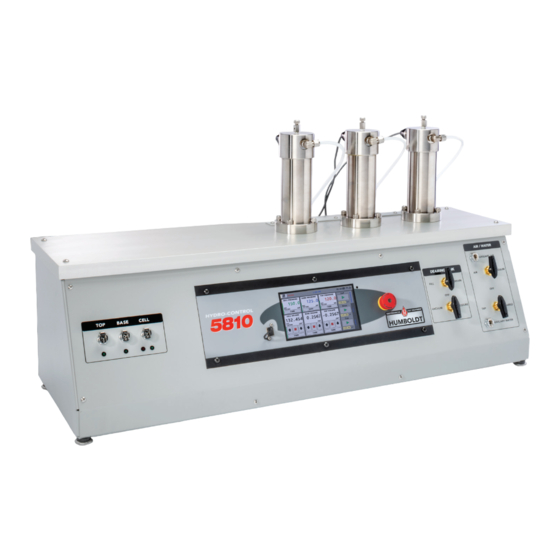
Its heavy-duty design and precise stepper-motor control provide a stable platform for years of reliable service allowing the HM-5810 to perform any tests required up to its load capacity of 3000 lbf (15kN). The HM-5810 is built around Humboldt’s integral, 4-channel data log- ger with touch-screen control, which allows it to be used as a stand- alone device capable of full test control and data logging. -
Page 60: General Warnings
The exclusive remedy for this warranty is Humboldt Mfg. Co., factory replacement of any part or parts of such product, for the warranty of this product please refer to Humboldt Mfg. Co. catalog on Terms and Conditions of Sale. The purchaser is responsible for the transportation charges. - Page 61 99 years. Transfer of the license can be obtained by a request, in writing, from HUMBOLDT MFG. CO. With the exception of HUMBOLDT Authorized Service Facilities, you may not copy, alter, decompile, or reverse assemble the software in any fashion except as instruct- ed in this manual.
- Page 64 Humboldt Mfg. Co. U.S.A. Toll Free: 1.800.544.7220 875 Tollgate Road Voice: 1.708.456.6300 Elgin, Illinois 60123 U.S.A. Fax: 1.708.456.0137 Email: hmc@humboldtmfg.com...
Need help?
Do you have a question about the HM-5810 and is the answer not in the manual?
Questions and answers