Table of Contents
Advertisement
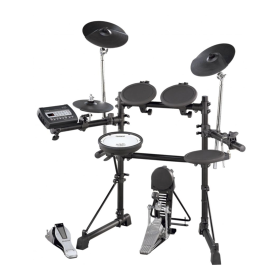
Owner's Manual
Thank you, and congratulations on your choice of the Roland Drum System TD-3KV.
201a
Before using this unit, carefully read the sections entitled: "USING THE UNIT
SAFELY" and "IMPORTANT NOTES" (p. 2; p. 3). These sections provide important
information concerning the proper operation of the unit. Additionally, in order to feel
assured that you have gained a good grasp of every feature provided by your new
unit, Owner's manual should be read in its entirety. The manual should be saved
and kept on hand as a convenient reference.
202
Copyright © 2005 ROLAND CORPORATION
All rights reserved. No part of this publication may be reproduced in any form without the
written permission of ROLAND CORPORATION.
Advertisement
Table of Contents

Related Manuals for Roland V-Drums TD-3KV


Summary of Contents for Roland V-Drums TD-3KV
- Page 1 Owner’s Manual Thank you, and congratulations on your choice of the Roland Drum System TD-3KV. 201a Before using this unit, carefully read the sections entitled: “USING THE UNIT SAFELY” and “IMPORTANT NOTES” (p. 2; p. 3). These sections provide important information concerning the proper operation of the unit.
- Page 2 Do not attempt to repair the unit, or replace parts within it (except when this manual provides specific instructions directing you to do so). Refer all servicing to your retailer, the nearest Roland Service Center, or an authorized Roland distributor, as listed on the “Information” page.
-
Page 3: Important Notes
(including padding) that it came in, if possible. Otherwise, you will need to use equivalent packaging materials. • Use a cable from Roland to make the connection. If using some other make of connection cable, please note the following precautions. -
Page 4: Check The Contents Of The Box
❑ CY-8 (Cymbal Pad) x 2 ❑ Connection Cables ❑ Tuning Key x 1 ■ TD-3KV Owner’s Manual x 1 • The tuning key is included in the FD-8 package. • The TD-3 Owner’s Manual is included in the TD-3 package. - Page 5 TD-3 (Percussion Sound Module) Attach the stand holder (included with the optional drum stand) to the TD-3. Using the screws attached to the bottom panel, attach the holder so the unit is oriented as shown in the diagram. fig.TD-3.e Narrow •...
-
Page 6: Adjusting The Head Tension
USING THE UNIT SAFELY PD-85BK (V-Pad) fig.PD-85.e_80 Hoop (Rim) Stand Fixing Screw Tuning Bolt Output Jack Holder Adjusting the Head Tension When adjusting, use the tuning key supplied with the FD-8. The PD-85BK is shipped from the factory with the head tension loosened. Be sure to adjust the tension before use. -
Page 7: Attaching The Pad To A Stand
Attaching the Pad to a Stand fig.PD-85-Set.e Tighten Loosen Pass the rod through the pipe that is inside the holder. When attaching the PD-85BK to the mount, be sure to tighten the stand fixing screw securely. If it remains loose, the pad could fall off. USING THE UNIT SAFELY Playing the PD-85BK fig.PD-85-HR.e_90... -
Page 8: Specifications
USING THE UNIT SAFELY Replacing the Head When the Head Should Be Replaced The head is an expendable item that eventually will wear out and need to be replaced. Replace the head when the following occurs: • The head surface is torn •... - Page 9 PD-8 (Pad) fig.PD-8.e Stand Fixing Screw Head Stand Fixing Screw Output Jack Attaching the Pad to a Stand fig.PD-Set.e Tighten Loosen Pass the rod through the pipe that is inside the holder. When attaching the PD-8s to the mounts, be sure to tighten the stand fixing screws securely.
- Page 10 Stopper (Be sure to orient it correctly) 2. Attach the CY-8 so the Roland logo is positioned on the opposite side of the playing area. 3. Tighten the wing nut to obtain the desired movement. Use the included felt washer and the wing nut.
- Page 11 FD-8 (Hi-Hat Control Pedal) fig.FD-8.e Adjusting the Travel of the Pedal Loosen the nut with the included tuning key. After adjusting, tighten the nut. deep Shift the Arm shallow Anchor Bolt Control Out Jack Attaching the Anchor Bolts (When Using on the Carpet) Anchor Bolt Spring for the Anchor Bolt...
-
Page 12: Making The Settings
USING THE UNIT SAFELY KD-8 (Kick Trigger Pad) fig.KD-8.e Output Jack Stand Anchor Bolt Foot Plate Making the Settings 1. Remove the screws attached to the reverse side of the KD-8’s trigger. fig.KD-Assy01 2. Pull out the stand in the direction indicated by the arrow until it is fully extended. - Page 13 1. Loosen the stand’s anchor bolts and remove the foot plate. fig.KD-Assy06 2. Set the kick pedal so that the entire bottom surface is attached to the floor. 3. In most cases, the stand becomes somewhat floated. Tighten the anchor bolts securely there to fix the stand and foot plate.
- Page 14 USING THE UNIT SAFELY Assemble the “TD-3KV” To prevent malfunction and/or damage to speakers or other devices, always turn down the volume, and turn off the power on all devices before making any connections. Using the provided cables, connect the pads, cymbal pads, hi-hat control pedal, and kick trigger.
- Page 16 3898823...
Need help?
Do you have a question about the V-Drums TD-3KV and is the answer not in the manual?
Questions and answers