
Related Manuals for Alarko OPTIMA 5/8


Summary of Contents for Alarko OPTIMA 5/8
- Page 1 OPTİMA 5/8, 4/10, 4/8, 4/4, 3/12-180, 3/10-180 3/7-180, 2/10-180 C�rculat�on Pump Operat�ng Instruct�on...
- Page 2 Code No: A.7.1.10� Rev�s�on Date: 26082022...
-
Page 3: Table Of Contents
CAUTION ............................1 WARNINGS AND SYMBOLS ......................1 Types of Symbols and Warn�ngs ..................... 1 GENERAL ............................2 Descr�pt�on of the Pump ......................2 Appl�cat�ons (Intended Use) ....................3 Pumped L�qu�ds ........................3 Operat�ng Cond�t�ons ....................... 3 Insulat�on Shells ........................4 CONTENTS OF THE PACKAGE, LIFTING, TRANSPORTATITON AND STORAGE .... -
Page 4: Caution
The manufacturer of the Opt�ma pumps, Alarko-Carr�er, prov�des customer serv�ce and reta�l�ng operat�ons on the f�elds of heat�ng, cool�ng, vent�lat�on, water treatment and pressur�zat�on nat�onw�de w�th �ts 68 years of exper�ence. Please contact your author�zed Alarko-Carr�er customer serv�ce �f you need any �nformat�on or encounter a problem. -
Page 5: General
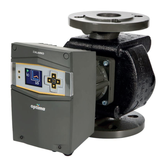
3. GENERAL 3.1 Descr�pt�on of the Pump Alarko Opt�ma �s a brand new type of c�rculat�on pump wh�ch regulates �ts speed accord�ng to the system needs by the ECM (Electron�c Commutated Motor) technology and the controller on �t, as well as saves energy w�th �ts var�ous types of operat�ng mode cho�ces. -
Page 6: Appl�Cat�Ons (Intended Use)
3.2 Appl�cat�ons (Intended Use) Alarko Opt�ma pumps are developed for the c�rculat�on and pressur�zat�on of the water flow�ng �n the heat�ng and a�r cond�t�on�ng systems located �n the res�dent�al, commerc�al and �ndustr�al establ�shments. Opt�ma pumps can be used only for the purposes that are stated �n th�s CAUTION manual. -
Page 7: Insulat�On Shells
3.5 Insulat�on Shells The �nsulat�on shell �s des�gned to m�t�gate the thermal losses �n heat�ng systems and del�vered w�th the pump. It �s made of polypropylene foam and thoroughly mounted on the pump by �ts perfectly f�tt�ng des�gn. Remove the �nsulat�on shells from the hous�ng before the pump �nstallat�on. See F�gure 3.2. F�gure 3.2: Insulat�on Shells 4. -
Page 8: Transportat�On And Storage
It �s adv�sed to check and exam�ne the product whether �t �s the ordered type and del�vered undamaged. If the pump �s damaged or deformed, �t should not be used w�thout an approval of the Alarko-Carr�er customer serv�ces. 5. PUMP DETAILS 5.1 Nameplate... -
Page 9: Techn�Cal Data
Number Descr�pt�on F�rst d�g�t of the nom�nal flange d�ameter Max. head Pump hous�ng length Product�on year M�n. and Max. power Temperature class Enclosure class Input frequency Input voltage Ser�al number Max. system pressure Acqu�red standards Max. current Energy Eff�c�ency Index (EEI) Operat�ng Instruct�on L�nk Factory Manufactur�ng Code Table 5.1: Descr�pt�on of the Nameplate Data... -
Page 10: Pump Installation
In order to avo�d the no�se and damage due to the cav�tat�on, the m�n�mum �nlet pressure values are g�ven on the table below. Water Temperature Nominal Diameter 50⁰C 75⁰C 95⁰C 110⁰C G1 1/2" 0,4 bar 0,7 bar 1,0 bar 1,5 bar 0,4 bar 0,7 bar 1,0 bar... - Page 11 F�gure 6.1: Correct Pump Pos�t�ons Wh�le Vert�cally and Hor�zontally Installed to the P�pework The pump must be not perpend�cular to the ground. F�gure 6.2: Incorrect Pump Pos�t�ons The pos�t�on of the control box can be changed �n order to see and use the d�splay eas�er. To adjust the pos�t�on, the 4 bolts, wh�ch hook the motor hous�ng and pump hous�ng together, are removed and the motor hous�ng �s adjusted by rotat�ng �t to the appropr�ate one from the allowed pos�t�ons and reconnected to the pump hous�ng w�th bolts.
-
Page 12: Mechan�Cal Installat�On
F�gure 6.3: Control Box Pos�t�on Adjustment 6.2 Mechan�cal Installat�on 1. Make sure that all the p�p�ng of the system must be done before beg�nn�ng the �nstallat�on. 2. Close the valves on the �nlet and outlet s�de to �solate the pump from water flow. 3. - Page 13 9. Check the F�gure 6.5 for washer, bolt and nut order. See Table 6.1 for the recommended t�ghten�ng torques for the bolts used �n the pump f�x�ng. Washer Bolt F�gure 6.5 Flanged P�pe Connect�on Pressure Bolt and Nut Type Recommended Tightening Torque Value PN 6 40 Nm - 60 Nm PN 10...
-
Page 14: F�Ll�Ng And Vent�Ng
Condensate Dra�n Grooves F�gure 6.6: Condensate Dra�n Grooves 12. After the �nstallat�on �s completed, place the �nsulat�on shells as shown �n F�gure 6.7. F�gure 6.7: Plac�ng the Insulat�on Shells 6.3 F�ll�ng and Vent�ng In order to ensure the pump to operate eff�c�ently also w�thout any damage and no�se, the a�r �n the system must be vented and the system pressure must be between the values g�ven �n Table 5.2 and Table 5.3. -
Page 15: Cable/Fuse Select�On And Electr�Cal Installat�On
6.4 Cable/Fuse Select�on and Electr�cal Installat�on Electr�cal �nstallat�on must be carr�ed out by qual�f�ed personnel and �n accordance w�th the �nstruct�ons on th�s manual and also w�th appl�cable regulat�ons. Before work�ng on the pump, all poles of the power supply must be d�sconnected. - Page 16 F�gure 6.9: Removal of the Bottom Cover 5. Pull the power supply cable through the no.1 cable gland shown �n F�gure 6.10. F�gure 6.10: Cable Gland V�ew 6. Connect the power supply cables to the socket named as “A” �n F�gure 6.10 appropr�ately, as shown �n F�gure 6.8.
-
Page 17: Parallel/Back-Up Operat�On
F�gure 6.11: Ref�tt�ng the Bottom Cover The power cable should not be �n contact w�th the pump or p�pel�ne. The voltage value of the ma�ns must be �n between the l�m�ts g�ven �n Table 5.2 It �s recommended to use a res�dual-current dev�ce (RCD) to protect the user and the pump. The RCD should be chosen accord�ng to the nom�nal voltage and current of the pump and �t should be able to tr�p on h�gh frequency leakages (type B) (The tr�pp�ng current should be lower than 3.5mA accord�ng to the EN 60335). -
Page 18: Display And Settings
7. DISPLAY AND SETTINGS The control d�splay shows the �nformat�on about the pump status and allows the user to set the des�red mode to operat�on. Opt�ma pumps have 3 d�fferent d�splay opt�ons wh�ch are graph�cal d�splay, 2-D�g�t and non-d�splay. 7.1 Graph�cal D�splay The graph�cal d�splay has 2 LEDs, f�ve control buttons and one TFT screen. - Page 19 Nu. 6 shows the current speed of the pump. In the ma�n menu; �t �s sw�tch�ng between operat�ng modes and pause the pump w�th the “OK” button and d�rect�on keys. A wh�te frame appears on the act�ve �con �n order to eas�ly sw�tch�ng between the menus and submenus.
- Page 20 Constant Pressure Operat�ng Mode Shows the selected head w�th 0.5 meter �ntervals. Constant Pressure Operat�ng Mode �s chosen from operat�ng modes and press the “OK” button after select�on. Press “Down” button to adjust des�red constant pressure operat�ng po�nt and then press “OK” button to select po�nt.
-
Page 21: 2-D�G�T D�Splay
2-D�g�t D�splay The two-d�g�t d�splay has f�ve LEDs, three control buttons and one LED screen wh�ch occur from two d�g�ts. See F�gure 7.2. F�gure 7.2: Control D�splay Layout of 2-D�g�t D�splay The layout of the buttons and d�splay: 1. Manuel Operat�ng LED: It �s on wh�le the pump runs �n manual operat�ng mode. 2. - Page 22 Constant Pressure Operat�ng Mode Shows the selected head w�th 0.5 meter �ntervals. The pump sets �n constant pressure operat�ng mode by press�ng the “MENU” button. “Constant Pressure Operat�ng LED” �s on wh�le the pump operates �n constant pressure operat�ng mode.
-
Page 23: First Start-Up, Continuous Operation And Shutdown
8. FIRST START-UP, CONTINUOUS OPERATION AND SHUTDOWN Depend�ng on the water temperature �n the p�pe system, any part of the pump �s subject to h�gh temperatures. In case of a contact to the non- plast�c surfaces, there �s a r�sk of burn and conflagrat�on. F�ll the system w�th water �n m�n�mum pressure and vent the a�r. -
Page 24: Operating Modes And Selection Criteria
��. Sw�tch off the power for 2-D�g�t D�splay and Non-D�splay types. ���. In the event of �nstalled add�t�onal accessor�es, the pump can be started/stopped v�a add�t�onal accessor�es. 9. OPERATING MODES AND SELECTION CRITERIA Opt�ma c�rculat�on pumps save energy w�th �ts var�ous types of operat�ng mode cho�ces, wh�ch they track the curves of system needs by the ECM technology. -
Page 25: Manual Operat�Ng Mode
9.1 Manual Operat�ng Mode F�gure 9.2: The curve of the Manual Mode In th�s operat�ng mode, the pump sets �ts speed f�xed on the selected rpm. The speed �s set by 50 rpm �ntervals. 9.2 Constant Pressure Operat�ng Mode ayar F�gure 9.3: The curve of the Constant Pressure Mode In th�s operat�ng mode, the pump sets �ts speed to keep the selected head value (H ) stable. -
Page 26: Var�Able Pressure Operat�Ng Mode
F�gure 9.4: Example of the Constant Pressure Mode 9.3 Var�able Pressure Operat�ng Mode ayar ayar F�gure 9.5: The curve of the Var�able Pressure Mode In th�s operat�ng mode, the pump sets �ts speed by track�ng a l�ne between the selected head value ) and half of �t, depend�ng on the flow changes �n the system. - Page 27 In the follow�ng graph, the curves of the operat�ng modes are drawn w�th 1 meter �ntervals. The head can be set by 0.5m �ntervals on the d�splay. Accord�ng to the rule g�ven above: 8.5m A �s set at 8.5m B �s set at C �s set at D �s set at The f�gure below �s g�ven as an example:...
-
Page 28: Operat�Ng Mode Select�On Cr�Ter�A
9.4 Operat�ng Mode Select�on Cr�ter�a The select�on of the operat�ng modes �s based on the cr�ter�a wh�ch are g�ven below: Manual Variable Pressure Constant Pressure Opera�ng Mode Opera�ng Mode Opera�ng Mode ayar ayar ayar * Del�very head loss > 4mSS * Very long d�str�but�on * Del�very head loss <... -
Page 29: Additonal Accessiories
Opt�ma pumps do not need any spec�al ma�ntenance s�nce the shaft and bear�ngs rotate �n water. Please v�s�t www.alarko-carr�er.com.tr or call +90 212 444 0 128 �f you encounter a problem or want to know the nearest customer serv�ce locat�on. -
Page 30: Faults, Causes And Remedies
FAULTS, CAUSES AND REMEDIES DİKKAT The troubleshoot�ng must only be done by author�zed serv�ce. Before start�ng work, sw�tch off the power supply. Beg�n work 1 m�nute after sw�tch�ng off the power. If any �mped�t�ve state occurs for the pump�ng operat�on, the pump automat�cally stops, g�ves a warn�ng code. - Page 31 Warn�ng Cause Remedy Code Input voltage �s above 245V. Ensure that the �nput voltage �s w�th�n spec�f�ed l�m�ts. Input voltage �s below 207V. Ensure that the �nput voltage �s w�th�n spec�f�ed l�m�ts. If the system has mult�ple pumps, make sure the pumps all operate The motor speed exceeds the setpo�nt speed.
- Page 32 Error Cause Remedy Code Check that water temperature �s w�th�n allowed range. Motor Temperature: Wa�t for the motor to cool down. Temperature of motor w�nd�ngs �s e�ther too h�gh or too low. To ver�fy that the motor temperature sensors are not damaged (shorted/open), call serv�ce support.
- Page 33 -To ver�fy that the motor temperature sensors or motor w�nd�ngs are - Faulty connect�on between motor not damaged (shorted/open), and to ver�fy the correct f�rmware on temperature sensor and control card. the card, call serv�ce support. - Faulty connect�on between motor w�nd�ngs -After repeated fa�lure, replace control card.
- Page 34 The fault flowchart of the pump �s g�ven below: F�gure 11.3: Fault Flowchart...
-
Page 35: Dismaltling
DISMALTLING D�smantl�ng of the pump must be carr�ed out by qual�f�ed personnel and �n accordance w�th the �nstruct�ons on th�s manual and also w�th appl�cable regulat�ons. Before d�smantl�ng, sw�tch off the power supply. All d�smantl�ng process must be done wh�le the power �s OFF. Wa�t unt�l the d�splay �s completely turned off. -
Page 36: Disposal
Sw�tch off the power to the pump. Wa�t 1 m�nute. D�sconnect the power supply cable. Close the valves on the �nlet and outlet s�de to �solate the pump from water flow. Remove the bolts, nuts, washers and then the pump hous�ng. DISPOSAL For the d�sposal of the pump, author�zed techn�cal serv�ces or related recycl�ng fac�l�t�es can be used. -
Page 37: Appandix
(mm) (mm) (mm) (mm) (mm) (mm) (mm) (mm) (mm) (mm) (mm) (kg) PN6 PN10 PN6 PN10 OPTIMA 5/8 166.0 110.0 125.0 102.0 50.0 4x14 4x18 129.5 96.0 69.7 57.5 240.0 183.0 152.0 232.0 88.0 83.0 OPTIMA 4/10 151.0 100.0 110.0 88.0... -
Page 38: General Select�On Chart And Performance Curves
15.2 General Select�on Chart and Performance Curves... - Page 39 OPTİMA 5/8 OPTİMA 5/8 MANUAL (C1-C2-C3) OPERATING MODE Q (m OPTİMA 5/8 4600 RPM MANUAL (RPM) OPERATING MODE 4200 RPM 3400 RPM 2600 RPM 1800 RPM Q (m...
- Page 40 OPTİMA 5/8 OPTİMA 5/8 CONSTANT PRESSURE OPERATING MODE Q (m OPTİMA 5/8 VARIABLE PRESSURE OPERATING MODE Q (m...
- Page 41 OPTİMA 4/10 OPTİMA 4/10-180 MANUAL (C1-C2-C3) OPERATING MODE Q (m OPTİMA 4/10-180 4600 RPM MANUAL (RPM) OPERATING MODE 4200 RPM 3400 RPM 2600 RPM 1800 RPM Q (m...
- Page 42 OPTİMA 4/10 OPTİMA 4/10-180 CONSTANT PRESSURE OPERATING MODE 10 m Q (m OPTİMA 4/10-180 VARIABLE PRESSURE OPERATING MODE 10 m Q (m...
- Page 43 OPTİMA 4/8 OPTİMA 4/8 MANUAL (C1-C2-C3) OPERATING MODE Q (m OPTİMA 4/8 4600 RPM MANUAL (RPM) OPERATING MODE 4200 RPM 3400 RPM 2600 RPM 1800 RPM Q (m...
- Page 44 OPTİMA 4/8 OPTİMA 4/8 CONSTANT PRESSURE OPERATING MODE Q (m OPTİMA 4/8 VARIABLE PRESSURE OPERATING MODE Q (m...
- Page 45 OPTİMA 4/4 OPTİMA 4/4 MANUAL (C1-C2-C3) OPERATING MODE Q (m OPTİMA 4/4 3600 RPM MANUAL (RPM) OPERATING MODE 3200 RPM 2400 RPM 1600 RPM Q (m...
- Page 46 OPTİMA 4/4 OPTİMA 4/4 CONSTANT PRESSURE OPERATING MODE Q (m OPTİMA 4/4 VARIABLE PRESSURE OPERATING MODE Q (m...
- Page 47 OPTİMA 3/12-180 OPTİMA 3/12-180 MANUAL (C1-C2-C3) OPERATING MODE Q (m OPTİMA 3/12-180 4900 RPM MANUAL (RPM) OPERATING MODE 4100 RPM 3300 RPM 2500 RPM 1800 RPM Q (m...
- Page 48 OPTİMA 3/12-180 OPTİMA 3/12-180 CONSTANT PRESSURE OPERATING MODE 11 m 10 m Q (m OPTİMA 3/12-180 VARIABLE PRESSURE OPERATING MODE 11 m 10 m Q (m...
- Page 49 OPTİMA 3/10-180 OPTİMA 3/10-180 MANUAL (C1-C2-C3) OPERATING MODE Q (m OPTİMA 3/10-180 4600 RPM MANUAL (RPM) OPERATING MODE 4200 RPM 3400 RPM 2600 RPM 1800 RPM Q (m...
- Page 50 OPTİMA 3/10-180 OPTİMA 3/10-180 CONSTANT PRESSURE OPERATING MODE 10 m Q (m OPTİMA 3/10-180 VARIABLE PRESSURE OPERATING MODE 10 m Q (m...
- Page 51 OPTİMA 3/7-180 OPTİMA 3/7-180 MANUAL (C1-C2-C3) OPERATING MODE Q (m OPTİMA 3/7-180 3800 RPM MANUAL (RPM) OPERATING MODE 3000 RPM 2200 RPM 1600 RPM Q (m...
- Page 52 OPTİMA 3/7-180 OPTİMA 3/7-180 CONSTANT PRESSURE OPERATING MODE Q (m OPTİMA 3/7-180 VARIABLE PRESSURE OPERATING MODE Q (m...
- Page 53 OPTİMA 2/10-180 OPTİMA 2/10-180 MANUAL (C1-C2-C3) OPERATING MODE Q (m OPTİMA 2/10-180 4600 RPM MANUAL (RPM) OPERATING MODE 4200 RPM 3400 RPM 2600 RPM 1800 RPM Q (m...
- Page 54 OPTİMA 2/10-180 OPTİMA 2/10-180 CONSTANT PRESSURE OPERATING MODE 10 m Q (m OPTİMA 2/10-180 VARIABLE PRESSURE OPERATING MODE 10 m Q (m...
- Page 55 : Z�yapaşa Bulvarı Çel�k Ap. No : 25/5-6, 01130 ADANA Tel: (0322) 457 62 23 - Fax: (0322) 453 05 84 ANTALYA : Mehmetç�k Mahalles� Aspendos Bulvarı No: 79/5 - ANTALYA web: www.alarko-carr�er.com.tr Tel: (0242) 322 00 29 - Fax: (0242) 322 87 66 �nfo@alarko-carr�er.com.tr : 444 0 128...
Need help?
Do you have a question about the OPTIMA 5/8 and is the answer not in the manual?
Questions and answers