Table of Contents
Advertisement
Quick Links
Advertisement
Table of Contents

Related Manuals for Alarko ALD Series


Summary of Contents for Alarko ALD Series
- Page 1 AL D ALDF 400-600 Series WATER BOOSTER Operating Manual...
- Page 2 Code No: D.3.1.7 Printing Date: 301213 Revision No: 301213...
- Page 3 ALD and ALDF 400-600 Series ALDF 400-600 Series WATER BOOSTER Operating Manual...
-
Page 4: Table Of Contents
TABLE OF CONTENTS Introduction General Warnings Warranty and Service General Features Installation Rules Water Booster Operation Membrane Tank (Pressure Compensating Tank) Connection of Membrane Tank Pre-gas Pressure Setting of Membrane Tank Pressure Switch Pressure Switch Setting Procedure Pressure Switch Settings Set Pressure and Minimum Frequency Setting Determination of Minimum Frequency Minimum Frequency Setting... -
Page 6: Introduction
For more detailed information about your device, please refer to the product brochure and, if necessary, contact our Customer Hotline at 444 0 128 to reach ALARKO CARRIER dealer and after-sales services. After commissioning the water booster, our authorized dealers and services will provide you with the necessary information regarding the use and maintenance of the water booster. -
Page 7: General Warnings
GENERAL WARNINGS Do not touch any part of your device or its settings for any reason, such as operating, adjusting, or maintaining it, except as described in this manual. The electrical connection of the installation must be disconnected before any intervention on the device for the purpose of cleaning, repair or maintenance. -
Page 8: Warranty And Service
ALARKO CARRIER where you purchased the water booster, and signed by you. Then one copy will be given to you and the other copy will be sent to ALARKO CARRIER Customer Service Department. You must maintain and keep your Warranty Certificate handy in order to show it to the authorized service personnel to carry out the warranty procedures during the service operations. -
Page 9: General Features
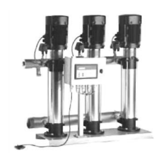
GENERAL FEATURES The main purpose of a water booster is to keep the pressurized water in the installation ready for use at any time. There are three main parts in a water booster. - Motor and Pump (Motopump) - Automatic Control Equipment: - Pressure Compensating Tank (must be purchased separately) Motopump: It pressurizes water. -
Page 10: Installation Rules
INSTALLATION RULES Location Selection: The place where the water booster will work should be closed in such a way that it is protected from external factors such as rain and frost. It should be placed in such a way that it is not affected by heat sources such as burners and boilers that may be present in the vicinity. - Page 11 The recommended assembly patterns are shown in the diagrams attached to this manual. Precautions to Extend the Service Life of Mechanical Seal: The mechanical seal is one of the most sensitive parts in the water booster. Inaccuracies or inadequacies in the installation and operating conditions cause the shaft seal to break down rapidly.
-
Page 12: Water Booster Operation
WATER BOOSTER OPERATION 1- Check the compatibility of the water and electrical installation. 2- Check that there is sufficient water in the water tank. 3- Check that the waterless running protection (if any) is properly installed. (See page 21 for details) 4- Check that the membrane tank has been installed correctly and that the pre-gas pressure is appropriate. -
Page 13: Membrane Tank (Pressure Compensating Tank)
MEMBRANE TANK (Pressure Compensating Tank) There are different applications for membrane tanks in water boosters; ALD and ALDF Water Booster: The user must use a membrane tank with the motopump assembly. The selection, installation and pressurization of this tank are described below. Note: These calculations are for finding the minimum value of the tank volume. -
Page 14: Connection Of Membrane Tank
CONNECTION OF MEMBRANE TANK The duty of the membrane tank is to reduce the number of switches (the number of starts and stops of the motor within 1 hour). Thus, the motopump does not need to be commissioned for small-scale uses. Therefore, the larger the tank, the lesser the number of switches. - Page 15 Air Pressure Values Required to be Pumped into the Tank for ALD Water Boosters Tank Tank Tank TYPE Pressure TYPE Pressure TYPE Pressure (bar) (bar) (bar) 403/10-1 403/10-2 403/10-3 403/15-1 403/15-2 403/15-3 403/16-1 403/16-2 403/16-3 406/11-1 406/11-2 406/11-3 406/15-1 406/15-2 406/15-3 406/18-1 406/18-2...
-
Page 16: Pressure Switch
PRESSURE SWITCH Table 2: Pressure Switch Features Brand Italtecnica Model PM/12 Place of Use ALD/ALDF Pressure Limits 3-12 bar Min. Differential Pressure 1,5 bar Max. Differential Pressure 4 bar Protection IP44 SETTING Stop pressure adjusting bolt PRESSURE SWITCH SETTING Starting pressure adjusting bolt The pressure switch has two spring bolts. - Page 17 The pressure switch adjustment should be made as follows. 1. Determine which pressure switches should be set to which values according to the table below. 2. Set the water booster to manual mode. For this purpose, press button 2 shown on page 20 for 10 seconds.
- Page 18 ALDF WATER BOOSTERS SET PRESSURE AND MINIMUM FREQUENCY SETTING 1. Set Pressure (Required Pressure) shall be determined according to installation conditions. Determination of Set Pressure Required Pressure h - Height (meter) between the place of water booster and top operating floor. △h - Pressure loss due to factors such as armature, water meter, calcified pipe in installation.
-
Page 19: Determination Of Minimum Frequency
3. DETERMINATION OF MINIMUM FREQUENCY Minimum frequency is found in Table-4 according to set pressure. TABLE - 4 MINIMUM FREQUENCY VALUES DEPENDING ON ALDF WATER BOOSTER SET PRESSURE 403/10 403/15 403/16 406/11 406/15 406/18 408/10 408/14 408/17 610/8 610/10 F (Hz) F (Hz) F (Hz) F (Hz) -
Page 20: Minimum Frequency Setting
MINIMUM FREQUENCY SETTING The minimum frequency is set via the frequency converter as described below. ■ How are parameters searched and reprogrammed Panel operation LED Display Operation First status. Displays the output frequency. Driver operation must be stopped before parameter changes can be made. "Mode"... - Page 21 ALDF Water Booster Factory Default Water Min. Reference Pmin Pmax Frequency Booster Pressure (Bar) (Bar) (Bar) (Hz) Type (Bar) 403/10 403/15 403/16 406/11 406/15 406/18 408/10 408/14 408/17 610/8 610/10 610/12 615/7 615/9 615/10 620/7 620/8 620/9 631/6 631/7 631/8...
-
Page 22: Pressure Transmitter
PRESSURE TRANSMITTER Pressure Transmitter Features Brand Keller Model PA-21 SR Place of Use ALDF Pressure Range 0-16 Bar Supply Voltage 8-28 V dc Output Signal 4-20mA Precision Class 0.5% Operating Temperature -40 ...+100 Line Connection G 1/4" Electrical Connection DIN43650 Protection Class IP 65... -
Page 23: Waterless Running Protection
WATERLESS RUNNING PROTECTION There are different applications on "waterless running protection" for Alarko water boosters. ALD Water Boosters: Protection is included in the standard delivery. Water float switch is used. ALDF Water Boosters: Minimum pressure and water float switch protection is available. -
Page 24: Installation Diagrams
INSTALLATION DIAGRAMS ALD and ALDF Series Building Installation Outlet City Water Inlet Overflow Control Max. Level Water Tank Min. Level Float Switch Drain 1. WATER BOOSTER 2. CHECK VALVE 3. VALVE 4. FLOATING TAP 5. STRAINER Figure 4... -
Page 25: Digital Control Panels Of Water Boosters With Twin And Triple Pumps
DIGITAL CONTROL PANELS OF WATER BOOSTERS WITH TWIN AND TRIPLE PUMPS The water boosters with twin and triple pump are equipped with control panel with microprocessor and LCD screen mounted on the panel cover. The front of the control panel is shown below. The panel changes according to the number of pumps. - Page 26 Screen Display During Normal Operation: There are two lines on the screen. The bottom line indicates the position/status of the device. On the top line, ALARKO - CARRIER will appear alternately with 4-5 seconds interval, together with the information on which engines are running and which ones have stopped.
- Page 27 Descriptions of messages that will appear on the ALDF Digital Display In normal operation, the display will show the pressure and control percentage (%) and the mode in which the water booster runs. While the water booster is in stop operation mode, the total running time and number of switches of each pump can be monitored on the screen by pressing the down arrow key.
- Page 28 ELECTRICAL DIAGRAM ALDM Series -Types: 403/10-1, 403/15-1, 403/16-1 0,75 MOTOR POWER MOTOR CURRENT 10,3 D TYPE K PUMP CONTACTOR K TYPE K PUMP CONTACTOR F THERMAL RELAY 10,3 Float Switch Pressure Switch...
- Page 29 ELECTRICAL DIAGRAM Single Phase Water Booster with Twin Pump Panel Terminal Connection ALDM Series - Types: 403/10-2, 403/15-2, 403/16-2 Channel Channel Rail Terminal...
- Page 30 ELECTRICAL DIAGRAM Single Phase Water Booster with Twin Pump Panel Power Circuit ALDM Series - Types: 403/10-2, 403/15-2, 403/16-...
- Page 31 ELECTRICAL DIAGRAM Single Phase Water Booster with Twin Pump Control Panel Connection ALDM Series - Types: 403/10-2, 403/15-2. 403/16-2...
- Page 32 ELECTRICAL DIAGRAM Single Phase Water Booster with Triple Pump Panel Terminal Connection ALDM Series - Types: 403/10-3, 403/15-3, 403/16-3 Channel Channel Rail Terminal...
- Page 33 ELECTRICAL DIAGRAM Single Phase Water Booster with Triple Pump Panel Power Circuit ALDM Series - Types: 403/10-3, 403/15-3, 403/16-3...
- Page 34 ELECTRICAL DIAGRAM Single Phase Water Booster with Triple Pump Control Panel Connection ALDM Series - Types: 403/10-3, 403/15-3, 403/16-3...
- Page 35 ELECTRICAL DIAGRAM ALD Series -Types: 403/10-1. 403/15-1, 403/16-1. 406/11-1, 406/15-1. 406/18-1. 408/10-1,408/14-1,408/17-1,610/8-1,610/10-1,610/12-1,615/7-1,615/9-1,620/7-1 0,75 MOTOR POWER MOTOR CURRENT 1,95 2,55 3,45 11,8 Pump contactor D type K type Pump contactor Thermal Relay 1,95 2,55 3,45 11,8 Float Pressure Switch Switch *NOTE: For Siemens 3TG10 type contactor.
- Page 36 ELECTRICAL DIAGRAM ALD Series - Types 615/10-1, 620/8-1, 620/9-1. 631/6-1, 631/7-1, 631/8-1...
- Page 37 ELECTRICAL DIAGRAM Direct Starter Water Booster with Twin Pump Panel Terminal Connection ALD Series - Types: 403/10-2, 403/15-2, 403/16-2, 406/11 -2, 406/15-2, 406/18-2, 408/10- 2, 408/14-2, 408/17-2, 610/8-2, 610/10-2, 610/12-2, 615/7-2, 615/9-2, 620/7-2 Channel Channel Rail Terminals...
- Page 38 ELECTRICAL DIAGRAM Direct Starter Water Booster with Twin Pump Panel Power Circuit ALD Series - Types: 403/10-2, 403/15-2, 403/16-2, 406/11-2, 406/15-2, 406/18-2, 408/10-2, 408/14-2, 408/17-2, 610/8-2, 610/10-2, 610/12-2, 615/7-2, 615/9-2, 620/7-2...
- Page 39 ELECTRICAL DIAGRAM Direct Starter Water Booster with Twin Pump Control Panel Connection ALD Series - Types: 403/10-2, 403/15-2, 403/16-2, 406/11-2, 406/15-2, 406/18-2. 408/10-2, 408/14-2, 408/17-2, 610/8-2, 610/10-2. 610/12-2, 615/7-2, 615/9-2, 620/7-2...
- Page 40 ELECTRICAL DIAGRAM Star/Triangle Starter Water Booster with Twin Pump Panel Terminal Connection ALD Series - Types: 615/10-2, 620/8-2, 620/9-2, 631/6-2, 631/7-2, 631/8-2 Channel Channel Rail Terminals...
- Page 41 ELECTRICAL DIAGRAM Star/Triangle Starter Water Booster with Twin Pump Panel Power Circuit Series - Types; 615/10-2, 620/8-2, 620/9-2, 631/6-2, 631/7-2, 631/8-2...
- Page 42 ELECTRICAL DIAGRAM Star/Triangle Starter Water Booster with Twin Pump Control Panel Connection ALD Series - Types: 615/10-2.620/8-2, 620/9-2, 631/6-2, 631/7-2,631/8-2...
- Page 43 ELECTRICAL DIAGRAM Direct Starter Water Booster with Triple Pump Panel Terminal Connection ALD Series - Types: 403/10-3, 403/15-3, 403/16-3. 406/11-3, 406/15-3. 406/18-3, 408/10- 3, 408/14-3, 408/17-3, 610/8-3, 610/10-3, 610/13-3, 615/7-3, 615/9-3, 620/7-3 Channel Channel Rail Terminals...
- Page 44 ELECTRICAL DIAGRAM Direct Starter Water Booster with Triple Pump Panel Power Circuit ALD Series - Types: 403/10-3, 403/15-3, 403/16-3, 406/11-3, 406/15-3, 406/18-3, 408/10-3, 408/14-3, 408/17-3, 610/8-3, 610/10-3, 610/13-3, 615/7-3, 615/9-3, 620/7-3...
- Page 45 ELECTRICAL DIAGRAM Direct Starter Water Booster with Triple Pump Control Panel Connection ALD Series-Types: 403/10-3, 403/15-3,403/16-3, 406/11-3, 406/15-3,406/18-3, 408/10-3, 408/14-3, 408/17-3, 610/8-3, 610/10-3, 610/13-3, 615/7-3, 615/9-3, 620/7-3...
- Page 46 ELECTRICAL DIAGRAM Star/Triangle Starter Water Booster with Triple Pump Panel Terminal Connection ALD Series - Types: 615/10-3, 620/8-3, 620/9-3, 631/6-3, 631/7-3, 631/8-3 Channel Channel Channel Rail Terminals...
- Page 47 ELECTRICAL DIAGRAM Star/Triangle Starter Water Booster with Triple Pump Panel Power Circuit ALD Series - Types: 615/10-3, 620/8-3, 620/9-3, 631/6-3, 631/7-3, 631/8-3...
- Page 48 ELECTRICAL DIAGRAM Star/Triangle Starter Water Booster with Triple Pump Control Panel Connection ALD Series - Types: 615/10-3, 620/8-3, 620/9-3, 631/6-3, 631/7-3, 631/8-3...
- Page 49 ELECTRICAL DIAGRAM Frequency Controlled Water Booster with Single Pump Panel Terminal Connection ALD Series - Types: 403/10-1, 403/15-1, 403/16-1, 406/11-1, 406/15-1, 406/18-1, 408/10-1,408/14-1, 408/17-1,610/8-1,610/10-1,610/11-1,615/7-1,615/9- 1,615/10-1, 620/7-1, 620/8-1,620/9-1, 631/6-1,631/7-1, 631/8-1 Channel Channel Driver Channel Rail Terminal...
- Page 50 ELECTRICAL DIAGRAM Frequency Controlled Water Booster with Single Pump Panel Power Circuit ALD Series - Types: 403/10-1. 403/15-1, 403/16-1, 406/11 -1, 406/15-1, 406/18-1, 408/10-1,408/14-1,408/17-1, 610/8-1,610/10-1,610/11-1,615/7-1,615/9-1,615/10-1, 620/7-1,620/8-1, 620/9-1, 631/6-1,631/7-1,631/8-1...
- Page 51 ELECTRICAL DIAGRAM Frequency Controlled Water Booster with Single Pump Control Panel Connection ALD Series - Types: 403/10-1, 403/15-1, 403/16-1, 406/11 - 1, 406/15- 1, 406/18-1, 408/10-1, 408/14-1, 408/17-1. 610/8-1. 610/10-1, 610/11-1, 615/7-1, 615/9-1, 615/10-1. 620/7-1, 620/8-1, 620/9-1, 631/6-1, 631/7-1, 631/8-1...
- Page 52 ELECTRICAL DIAGRAM Frequency Controlled Direct Starter Water Booster with Twin Pump Panel Terminal Connection ALD Series - Types: 403/10-2, 403/15-2, 403/16-2, 406/11 -2, 406/15-2, 406/18-2, 408/10-2, 408/14-2, 408/17-2, 610/8-2, 610/10-2, 610/12-2, 615/7-2, 615/9- 2, 620/7-2 Channel Channel Channel Driver Channel...
- Page 53 ELECTRICAL DIAGRAM Frequency Controlled Direct Starter Water Booster with Twin Pump Panel Power Circuit ALD Series - Types: 403/10-2, 403/15-2, 403/16-2,406/11 -2, 406/15-2, 406/18-2. 408/10-2, 408/14-2, 408/17-2, 610/8-2, 610/10-2, 610/12-2, 615/7-2, 615/9-2, 620/7-2...
- Page 54 ELECTRICAL DIAGRAM Frequency Controlled Direct Starter Water Booster with Twin Pump Control Panel Connection ALD Series - Types; 403/10-2, 403/15-2, 403/16-2, 406/11 -2. 406/15-2, 406/18-2, 408/10-2, 408/14-2, 408/17-2, 610/8-2, 610/10-2, 610/12-2, 615/7-2.615/9-2. 620/7-2...
- Page 55 ELECTRICAL DIAGRAM Frequency Controlled Star/Triangle Starter Water Booster with Twin Pump Panel Terminal Connection ALD Series - Types: 615/10-2, 620/8-2, 620/9-2, 631/6-2, 631/7-2, 631/8-2 Channel Channel Driver Channel Channel Rail Terminals...
- Page 56 ELECTRICAL DIAGRAM Frequency Controlled Star/Triangle Starter Water Booster with Twin Pump Panel Power Circuit ALD Series - Types: 615/10-2, 620/8-2, 620/9-2,631/6-2,631/7- 2,631/8-2...
- Page 57 ELECTRICAL DIAGRAM Frequency Controlled Star/Triangle Starter Water Booster with Twin Pump Control Panel Connection - Types: ALD Series 615/10-2, 620/8-2, 620/9-2. 631/6-2, 631/7-2, 631/8-2...
- Page 58 ELECTRICAL DIAGRAM Frequency Controlled Direct Starter Water Booster with Triple Pump Panel Terminal Connection ALD Series - Types: 403/10-3, 403/15-3, 403/16-3, 406/11-3, 406/15-3, 406/18-3, 408/10-3, 408/14-3, 408/17-3. 610/8-3, 610/10-3, 610/13-3, 615/7-3, 615/9-3, 620/7-3 Channel Channel Channel Driver Channel Rail Terminal...
- Page 59 ELECTRICAL DIAGRAM Frequency Controlled Direct Starter Water Booster with Triple Pump Panel Power - Types: Circuit ALD Series 403/10-3, 403/15-3. 403/16-3. 406/11 -3, 406/15-3, 406/18-3, 408/10-3. 408/14-3, 408/17-3, 610/8-3, 610/10-3, 610/13-3, 615/7-3, 615/9-3, 620/7-3...
- Page 60 ELECTRICAL DIAGRAM Frequency Controlled Direct Starter Water Booster with Triple Pump Control Panel - Types: Connection ALD Series 403/10-3, 403/15-3, 403/16-3, 406/11-3, 406/15-3. 406/18-3, 408/10-3, 408/14-3, 408/17-3, 610/8-3, 610/10-3, 610/13-3, 615/7-3, 615/9-3, 620/7-3...
- Page 61 ELECTRICAL DIAGRAM Frequency Controlled Star/Triangle Starter Water Booster with Triple Pump Panel Terminal Connection ALD Series - Types: 615/10-3, 620/8-3, 620/9-3, 631/6-3, 631/7-3, 631 /S-3 Channel Channel Channel Driver Channel Rail Terminals...
- Page 62 ELECTRICAL DIAGRAM Frequency Controlled Star/Triangle Starter Water Booster with Triple Pump Panel Power Circuit ALDF Series - Types: 615/10-3, 620/8-3, 620/9-3, 631/6-3, 631/7-3, 631/8-3...
- Page 63 ELECTRICAL DIAGRAM Frequency Controlled Star/Triangle Starter Water Booster with Triple Pump Control Panel Connection - Types: ALD Series 515/10-3, 620/8-3, 620/9-3, 631/6-3, 631/7-3, 631/8-3...
-
Page 64: Troubleshooting Guide
TROUBLESHOOTING GUIDE If the water booster is not working: a) Electricity: Check the power supply. b) Tank (For ALD and ALDF): Check that there is sufficient water in the tank. If there is no water in the tank, waterless running protection has been activated and cut off the electricity. -
Page 65: Technical Specifications
TECHNICAL SPECIFICATIONS / ALD and ALDF The motors of all types are 3-phase, 380 V, 50Hz. It is possible to turn the connection type of the water boosters which have 1, 1.5, 2, 3 or 4 HP motors to triangle and to operate in single phase network with the addition of suitable capacitor. - Page 66 Table 5: Technical Specifications Table / ALDM...
- Page 67 DIMENSIONS WATER BOOSTERS WITH SINGLE PUMP TYPES 403/10-1* 403/15-1* 1094 403/16-1* 1144 403/10-1 403/15-1 1089 403/16-1 1136 406/11-1 1129 406/15-1 1326 406/18-1 1485 1052 408/10-1 1131 408/14-1 1341 408/17-1 1495 1043 574.8 805. 1042.5 583.5 101.5 610/8-1 610/10-1 586.8 817. 1151.5 673.5 101.5...
- Page 68 ALDM WATER BOOSTERS DIMENSIONS WATER BOOSTERS WITH SINGLE PUMP TYPES 403/10-1 278 200 40,/15-1 278 200 1094 403/16-1 278 200 1144 WATER BOOSTERS WITH TWIN PUMPS TYPES 403/10-2 616 378 502 403/15-2 616 378 502 1094 403/16-2 616 378 502 1144 WATER BOOSTERS WITH TRIPLE PUMPS TYPES...
- Page 69 ALDF WATER BOOSTERS WITH FREQUENCY CONVERTOR DIMENSIONS WATER BOOSTERS WITH SINGLE TYPES 403/10-1 403/15-1 1089 403/16-1 1136 406/11-1 1129 406/15-1 1326 406/16-1 1485 1052 408/10-1 1131 408/14-1 1341 408/17-1 1495 1043 610/8-1 1105 125,5 610/10-1 1214 125,5 610/12-1 1355 125,5 615/7-1 1128 125,5...
-
Page 70: Ec Declaration Of Conformity
EC DECLARATION OF CONFORMITY EC Declaration of Conformity ALARKO Carrier San.Tic. A.Ş. ALK-10, ALK-15, ALK-20, ALK-25, ALK-30, ALK-35, ALD-403, ALD-406, ALD-408, ALD-610,ALD-615, ALD-620,ALD-631 water boosters Machine Safety Electromagnetic Compatibility Electrical Equipment Designed for Use within Specific Voltage Limits declares that it complies with the EC regulations specified above and takes full responsibility in this regard. - Page 71 EMERGENCY NUMBERS Natural Gas Emergency Fire Call Police Emergency Gendarmerie Emergency Water Emergency Power Cut Alarko Carrier Authorized Dealer Alarko Carrier Authorized Service...
- Page 73 İSTANBUL : GOSB - Gebze Org. San. Bölgesi, Ş. Bilgisu Cad. 41480 Gebze-KOCAELI Phone: (0262) 648 60 00 - Fax: (0262) 648 60 08 ANKARA : Sedat Simavi Sok. No: 48, 06550 Çankaya - ANKARA Phone: (0312) 409 52 00 - Fax: (0312) 440 79 30 İZMİR...
Need help?
Do you have a question about the ALD Series and is the answer not in the manual?
Questions and answers