
Related Manuals for Alarko ALDP Series


Summary of Contents for Alarko ALDP Series
- Page 1 ALDP and ALDPF SERIES WATER BOOSTERS WITH INLINE (COAXIAL) PUMP OPERATION AND MAINTENANCE MANUAL...
- Page 2 Code No: A.3.1.8 Printing Date: 171218 Revision No: 171218 Bulletin No: 17-1061...
- Page 3 ALDP and ALDPF SERIES WATER BOOSTERS WITH INLINE (COAXIAL) PUMP OPERATION AND MAINTENANCE MANUAL...
-
Page 5: Table Of Contents
TABLE OF CONTENTS INTRODUCTION ..........................7 GENERAL WARNINGS ........................ 7 WARRANTY AND SERVICE ......................8 GENERAL SPECIFICATIONS ...................... 9 HANDLING ............................. 10 INSTALLATION RULES ....................... 10 WATER BOOSTER OPERATION ....................12 CONNECTION OF MEMBRANE TANK ..................16 PRE-GAS PRESSURE SETTING OF MEMBRANE TANK ............16 PRESSURE SWITCH ADJUSTMENT BY DEVICE TYPE ON WATER BOOSTERS .... -
Page 7: Introduction
First of all, thank you for choosing ALARKO brand. In this manual you will find operation and maintenance information for ALARKO ALDP and ALDPF Series Water Boosters with Inline (Coaxial) Pump. Please read this manual carefully to operate your water booster with high efficiency and in an economical way and to ensure long and trouble-free use. -
Page 8: Warranty And Service
“www.alarko-carrier.com.tr”. If you encounter any problems, you can call the Customer Hotline at 444 0128 with domestic tariff across all cities of Turkey, or you can reach Alarko Carrier Customer Service... -
Page 9: General Specifications
GENERAL FEATURES The main purpose of a water booster is to keep the pressurized water in the installation ready for use at any time. There are three main parts in a water booster. - Motor and Pump (Motopump) - Automatic Control Equipment: - Pressure Compensating Tank (must be purchased separately) Motopump: It pressurizes water. -
Page 10: Handling
HANDLING Follow the instructions for handling the pumps: - Pumps with motor power from 0,37 to 5,5 kW: Lift the pump from the pump head with a hanger or similar tool. - Pumps with motor power from 7,5 to 22 kW: Lift the pump with the eye bolt. - Page 11 The bottom of the tank should be in the same plane as the water booster. This ensures that there is always water in the water booster suction inlet and prevents the pump from producing air. Suction from the tank at the lower level should never be done. Damage that may occur on the water booster as a result of such applications is not covered by the warranty.
-
Page 12: Water Booster Operation
The mechanical seal is at great risk in the following incorrect or inadequate operating conditions; • If the motopump is sucking from the tank at the low level; This type of installation should not be done. There is a possibility of leakage of the valve at the suction end. - Page 13 11- When a steady flow of fluid occurs, bleed the system and re-tighten. Fully open the discharge valve (See Figure 7). 12- For multi-pump water boosters, check that the pumps rotate each time they run. If the same pump always runs, there is a fault in the pressure switch connections.
- Page 14 Figure 7 Figure 6 ALDP I3 and I5 For these types, we recommend opening the bypass valve during operation (See Figure 8.) The bypass valve makes filling easier. In case of stationary operation, close the bypass valve again. If the operating pressure is less than 6 bar during the transfer of air containing liquids, we recommend leaving the bypass valve open.
- Page 15 MEMBRANE TANK (Pressure Compensating Tank) There are different applications for membrane tanks in water boosters; ALDP and ALDPF Water Booster: The user must use a membrane tank with the motopump assembly. The selection, installation and pressurization of this tank are described below. Note: These calculations are for finding the minimum value of the tank volume.
-
Page 16: Connection Of Membrane Tank
CONNECTION OF MEMBRANE TANK The duty of the membrane tank is to reduce the number of switches (the number of starts and stops of the motor within 1 hour). Thus, the motopump does not need to be commissioned for small-scale uses. Therefore, the larger the tank, the lesser the number of switches. -
Page 17: Pressure Switch Adjustment By Device Type On Water Boosters
Calculate the air required to be pumped into the tank for ALDP water boosters according to Table 1. While the air is being pumped, the water booster must be disconnected from the water in the installation and any water remained in the water booster must be drained. - Page 18 Water Booster with Twin and Triple Pump Note: In the water boosters with twin and triple pump, there is a delay of about 3 seconds for the motopump to detect the signal to prevent the pressure switch from being affected by the water hammer pulse. This delay should be considered as standard deviation.
- Page 19 Table 1: Booster Pressure Switch Setting Table Single Pump Twin Pump Triple Pump Water Booster 1. Pump 1. Pump 2. Pump 1. Pump 2. Pump 3. Pump Type Start/Stop Start/Stop Start/Stop Start/Stop Start/Stop Start/Stop 2,5-4,5 2,5-4,5 3,5-6,5 3,5-6,5 5,5-8,5 5,5-8,5 ALDP I3 10-14,5 10-14,5...
-
Page 20: Water Boosters Set Pressure And Minimum Frequency Setting
ALDP WATER BOOSTERS SET PRESSURE AND MINIMUM FREQUENCY SETTING 1. Set Pressure (Required Pressure) shall be determined according to installation conditions. Determination of Set Pressure Required Pressure = Hmin (mSS) = h + ∆h + 15 h - Height (meter) between the place of water booster and top operating floor. - Page 21 DETERMINATION OF MINIMUM FREQUENCY Minimum Frequency Setting The minimum frequency is set via the frequency converter as described below. How are parameters searched and reprogrammed? Panel Led Display Operation operation First status displays the Output frequency. Driver operation must be stopped before parameter changes can be made.
-
Page 22: Pressure Transmitter
Electrical Connection DIN 43650 Protection Class IP 65 WATERLESS RUNNING PROTECTION There are different applications on "waterless running protection" for Alarko water boosters. ALDP Water Boosters: Protection is included in the standard delivery. Water floar switch is used. ALDPF Water Boosters: Minimum pressure and float switch protection is available. -
Page 23: Installation Diagrams
DISASSEMBLY OF ONE OF THE PUMPS If one of the pumps of the water boosters with twin or triple pumps is removed for repair or maintenance, the remaining pump(s) may continue to run without having to change the electrical connections. To run the system, the following procedure must be followed. -
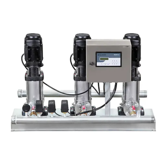
Page 24: Digital Control Panels Of Water Boosters With Twin And Triple Pumps
DIGITAL CONTROL PANELS OF WATER BOOSTERS WITH TWIN AND TRIPLE PUMPS The water boosters with twin and triple pump are equipped with control panel with microprocessor and LCD screen mounted on the panel cover. The front of the control panel is shown below. The panel changes according to the number of pumps. - Page 25 Screen Display During Normal Operation: There are two lines on the screen. The bottom line indicates the position/status of the device. On the top line, ALARKO - CARRIER will appear alternately with 4-5 seconds interval, together with the information on which engines are running and which ones have stopped.
- Page 26 Encrypted Section: This section is only for use by authorized services. Password can be entered by typing. Some settings of the water booster are made and historical information can be learned. Table 2: ALDP Water Booster Panel Dimensions SINGLE PUMP TWIN PUMP TRIPLE PUMP MOTOR POWER (HP)
- Page 27 Descriptions of messages that will appear on the ALDPF Digital Display In normal operation, the display will show the pressure and control percentage (%) and the mode in which the water booster runs. While the water booster is in stop operation mode, the total running time and number of switches of each pump can be monitored on the screen by pressing the down arrow key.
-
Page 28: Electrical Diagrams
ALDP SERIES WATER BOOSTER WITH COMPACT FLOAT SWITCH Types: I3/10, I3/13, I3/17, I3/27, I3/31, I5/8, I5/11, I5/14, I5/22, I5/26, I10/5, I10/7, I10/9, I10/16, I15/5, I15/7, I20/5 ELECTRICAL DIAGRAM Float Pressure Switch Switch * NOTE: For Siemens 3TG10 type contactor. - Page 29 ALDP SERIES S/T STARTER WATER BOOSTER WITH SINGLE PUMP Types; I10/18, I15/8, I20/7, I32/4, I15/10, I15/12, I20/8, I20/10, I32/5, I32/6, I45/3, I20/12, I45/4, I64/3, I90/3 ELECTRICAL DIAGRAM Operating Pressure Switch...
- Page 30 ALDP TYPE DIRECT STARTER WATER BOOSTER WITH TWIN PUMP Types; I3/10, I3/13, I3/17, I3/27, I3/31, I5/8, I5/11, I5/14, I5/22, I5/26, I10/5, I10/7, I10/9, I10/16, I15/5, I15/7, I20/5 ELECTRICAL DIAGRAM Operator Panel PANEL LAYOUT Channel Channel Terminals...
- Page 31 CONTROL PANEL CONNECTION Dialog Plus (END07-110) K11.K21 : Contactors TR: Transformer Q1 ,Q2 : Thermal Magnetic Switch FSR: Phase Sequencing and Protection Relay SE : Water Level Contact AB : Low Pressure YB: High Pressure PE : Earth Bus R,S,T,N : 380V AC+Neutral Network Input...
- Page 32 ALDP TYPE S/T STARTER WATER BOOSTER WITH TWIN PUMP Types; I10/18, I15/8, I20/7, I32/4, I15/10, I15/12, I20/8, I20/10, I32/5, I32/6, I45/3, I20/12, I45/4, I64/3, I90/3 ELECTRICAL DIAGRAM Operator Panel PANEL LAYOUT Channel Channel Terminals...
- Page 33 CONTROL PANEL CONNECTION Dialog Plus (END07-110) K11,K12,K13,K21,K22,K23 : Contactors : Transformer Q1 ,Q2: Thermal Magnetic Switch : Phase Sequencing and Protection Relay : Water Level Contact : Low Pressure : High Pressure : Earth Bus P1.P2 : Motor Terminal R,S,T : 380V AC Network Input...
- Page 34 ALDP TYPE DIRECT STARTER WATER BOOSTER WITH TRIPLE PUMP Types; I3/10, I3/13, I3/17, I3/27, I3/31, I5/8, I5/11, I5/14, I5/22, I5/26, I10/5, I10/7, I10/9, I10/16, I15/5, I15/7, I20/5 ELECTRICAL DIAGRAM Operator Panel PANEL LAYOUT Channel Channel Terminals...
- Page 35 CONTROL PANEL CONNECTION Dialog Plus (END07-110) K11.K21.K31 : Contactors TR: Transformer Q1 ,Q2,Q3 : Thermal Magnetic Switch FSR : Phase Sequencing and Protection Relay SE : Water Level Contact AB : Low Pressure OB : Medium Pressure YB: High Pressure PE : Earth Bus R,S,T,N : 380V AC+Neutral Network Input...
- Page 36 ALDP TYPE S/T STARTER WATER BOOSTER WITH TRIPLE PUMP Types; I10/18, I15/8, I20/7, I32/4, I15/10, I15/12, I20/8, I20/10, I32/5, I32/6, I45/3, I20/12, I45/4, I64/3, I90/3 ELECTRICAL DIAGRAM Operator Panel PANEL LAYOUT Channel Channel Channel Terminals...
- Page 37 CONTROL PANEL CONNECTION Dialog Plus (END07-110) K11,K12,K13,K21,K22,K23,K31,K32,K33: Contactors : Transformer Q1 ,Q2,Q3 : Thermal Magnetic Switch : Phase Sequencing and Protection Relay : Water Level Contact : Low Pressure : Medium Pressure : High Pressure : Earth Bus P1,P2,P3 : Motor Terminal R,S,T,N : 380V AC+Neutral Network Input...
- Page 38 ALDPF TYPE FREQUENCY INVERTER STARTER WATER BOOSTER WITH SINGLE PUMP Types; I3/10, I3/13, AI3/17, I3/27, I3/31, I5/8, I5/11, I5/14, I5/22, I5/26, I10/5, I10/7, I10/9, I10/16, I15/5, I15/7, I20/5, I10/18, I15/8, I20/7, I32/4, I15/10, I15/12, I20/8, I20/10, I32/5, I32/6, I45/3, I20/12, I45/4, I64/3, I90/3 ELECTRICAL DIAGRAM PANEL LAYOUT Driver...
- Page 39 CONTROL PANEL CONNECTION Dialog Plus (END07-110) R1 : Driver starter relay : Transformer YB : High Pressure Contact SA : Driver Fault Contact (FLA-FLC) SE : Water Level Contact PT : Pressure Transmitter PE : Earth Bus U,V,W Motor Terminal R,S,T,N : 380V AC+Neutral Network Input F1,F2,F3: Automatic Fuse...
- Page 40 ALDPF TYPE FREQUENCY INVERTER & DIRECT STARTER WATER BOOSTER WITH TWIN PUMP Types; I3/10, I3/13, I3/17, I3/27, I3/31, I5/8, I5/11, I5/14, I5/22, I5/26, I10/5, I10/7, I10/9, I10/16, I15/5, I15/7, I20/5 ELECTRICAL DIAGRAM PANEL LAYOUT Channel Driver Channel Channel Terminals...
- Page 41 CONTROL PANEL CONNECTION Dialog Plus (END07-110) K11 :Contactor : Driver starter relay TR : Transformer : Thermal Magnetic Switch FSR : Phase Sequencing and Protection Relay : High Pressure Contact : Driver Fault Contact (FLA-FLC) : Water Level Contact PT : Pressure Transmitter : Earth Bus U,V,W: Motor Terminal R,S,T,N : 380V AC+Neutral Network Input...
- Page 42 ALDPF TYPE FREQUENCY INVERTER & S/T STARTER WATER BOOSTER WITH TWIN PUMP Types; I10/18, I15/8, I20/7, I32/4, I15/10, I15/12, I20/8, I20/10, I32/5, I32/6, I45/3, I20/12, I45/4, I64/3, I90/3 ELECTRICAL DIAGRAM PANEL LAYOUT Channel Driver Channel Channel Terminals...
- Page 43 CONTROL PANEL CONNECTION Dialog Plus (END07-110) K11,K12,K13:Contactor R1 : Driver starter relay TR : Transformer Q1 : Thermal Switch NC Contacts FSR : Phase Sequencing and Protection Relay YB : High Pressure Contact SA : Driver Fault Contact (FLA-FLC) SE : Water Level Contact PT : Pressure Transmitter PE : Earth Bus P1.P2 : Motor Terminal...
- Page 44 ALDPF TYPE FREQUENCY INVERTER & DIRECT STARTER WATER BOOSTER WITH TRIPLE PUMP Types; I3/10, I3/13, I3/17, I3/27, I3/31, I5/8, I5/11, I5/14, I5/22, I5/26, I10/5, I10/7, I10/9, I10/16, I15/5, I15/7, I20/5 ELECTRICAL DIAGRAM PANEL LAYOUT Channel Channel Driver Channel Terminals...
- Page 45 CONTROL PANEL CONNECTION Dialog Plus (END07-110) K11.K21 : Contactors R1 : Driver starter relay TR: Transformer Q1 ,Q2 : Thermal Magnetic Switch FSR : Phase Sequencing and Protection Relay YB: High Pressure Contact SA : Driver Fault Contact (FLA-FLC) SE : Water Level Contact PT: Pressure Transmitter PE: Earth Bus U,V,W: Motor Terminal...
- Page 46 ALDPF TYPE FREQUENCY INVERTER & DIRECT STARTER WATER BOOSTER WITH TRIPLE PUMP Types; I3/10, I3/13, I3/17, I3/27, I3/31, I5/8, I5/11, I5/14, I5/22, I5/26, I10/5, I10/7, I10/9, I10/16, I15/5, I15/7, I20/5 ELECTRICAL DIAGRAM PANEL LAYOUT Channel Driver Channel Channel Channel Terminals...
- Page 47 CONTROL PANEL CONNECTION Dialog Plus (END07-110) K11,K12,K13,K21,K22,K23 : Contactors R1 : Driver starter relay TR : Transformer Q1,Q2 : Thermal Magnetic Switch FSR : Phase Sequencing and Protection Relay YB : High Pressure Contact SA : Driver Fault Contact (FLA-FLC) SE : Water Level Contact PT : Pressure Transmitter PE : Earth Bus...
- Page 48 MINIMUM INPUT PRESSURE – NPSH : The maximum suction height (“H”) is calculated as follows: = Pb x 10.2 - NPSH - Hf - Hv - Hs = Barometric pressure. The pressure should be set to 1 bar. Pb in closed systems indicates the system pressure in bar.
- Page 49 EXAMPLE: Pb = 1 bar Pump type = ALDP I10 Flow rate = 10 m NPSH (See Pump Curves) = 2.1 meters Liquid temperature = 50° Hv (Vapor pressure) = 1.3 Hf = 3 meters Hm H = Pb x 10.2-NPSH - Hf - Hv - Hs H = 1x10.2-2.1-3.0-1.3-0.5 = 3.3 meters This means that the pump can operate a suction lift with a maximum head of 3.3 meters.
-
Page 50: Maximum Input Pressure And Operating Pressure
MAXIMUM INPUT PRESSURE AND OPERATING PRESSURE Table 4 shows the maximum permissible input pressure. However, the sum of the current input pressure and the pressure in the closed valve must be lower than the maximum permissible operating pressure. If the maximum permissible operating pressure is exceeded, the conical bearing on the motor may be damaged and the service life of the shaft seal may be reduced. - Page 51 Determination of operating and input pressures: Operating and input pressures should be handled together. EXAMPLE 1: Pump Type/Level = ALDP I5 /12 Max. operating pressure = 25 bar Max. input pressure = 15 bar Closed valve pressure = 14.6 bar (See Pump Curves) This pump is not allowed to operate at an input pressure of 15 bar.
-
Page 52: Pump Curves
PUMP CURVES GENERAL SELECTION CURVES SINGLE PUMP TWIN PUMP TRIPLE PUMP... - Page 53 ALDP I3 SINGLE PUMP TWIN PUMP TRIPLE PUMP...
- Page 54 ALDP I5 SINGLE PUMP TWIN PUMP TRIPLE PUMP...
- Page 55 ALDP I10 SINGLE PUMP TWIN PUMP TRIPLE PUMP...
- Page 56 ALDP I15 SINGLE PUMP TWIN PUMP TRIPLE PUMP...
- Page 57 ALDP I20 SINGLE PUMP TWIN PUMP TRIPLE PUMP...
- Page 58 ALDP I32 SINGLE PUMP TWIN PUMP TRIPLE PUMP...
- Page 59 ALDP I45 SINGLE PUMP TWIN PUMP TRIPLE PUMP...
-
Page 60: Technical Specifications
ALDP I64 SINGLE PUMP TWIN PUMP TRIPLE PUMP TECHNICIAL SPECIFICATIONS The motors of all types are 3-phase, 380 V, 50Hz. Protection against waterless running is done with float switch. Water boosters should be used with a pressure compensating tank. Tank coupling with pump assembly can be easily done with flexible connection hose. - Page 61 Table 5: Technical Specifications Table Weight SINGLE PUMP MOTOR WATER ALDP ALDPF Connectio INLET/OUTLET** TYPES POWER ALDP I3/10-1 ALDP I3/13-1 ALDP I3 ALDP I3/17-1 ALDP I3/27-1 ALDP I3/31-1 DN32/DN32 ALDP I5 /8-1 11 ALDP I5 /11-1 ALDP I5 14 ALDP I5 /14-1 22 ALDP I5 /22-1 26 ALDP I5 /26-1 ALDP I10 /5-1...
- Page 62 Weight SINGLE PUMP TWIN PUMP MOTOR WATER ALDP ALDPF Connecti INLET/OUTLET** TYPES TYPES POWER ALDP I3/10-1 ALDP I3/10-2 ALDP I3/13-1 ALDP I3/13-2 ALDP I3/17-1 ALDP I3/17-2 ALDP I3 ALDP I3 ALDP I3/27-1 ALDP I3/27-2 ALDP I3/31-1 ALDP I3/31-2 DN50/DN50 ALDP I5 /8-1 ALDP I5 /8-2 ALDP I5 /11-1 ALDP I5 /11-2...
- Page 63 Weight SINGLE PUMP TRIPLE PUMP MOTOR WATER ALDP ALDP Connecti INLET/OUTLET** TYPES TYPES POWER ALDP I3/10-1 ALDP I3/10-3 ALDP I3/13-1 ALDP I3/13-3 ALDP I3/17-1 ALDP I3/17-3 ALDP I3 ALDP I3 ALDP I3/27-1 ALDP I3/27-3 ALDP I3/31-1 ALDP I3/31-3 DN50/DN50 ALDP I5 /8-1 ALDP I5 /8-3 ALDP I5 /11-1 ALDP I5 /11-3...
-
Page 64: Water Booster Dimensions
SINGLE PUMP ALDP and ALDPF WATER BOOSTER DIMENSIONS SINGLE PUMP TYPES SINGLE PUMP TYPES ALDP I3 ALDP I3/10-1 ALDPF I3 ALDPF I3/10-1 ALDP I3/13-1 ALDPF I3/13-1 ALDP I3/17-1 ALDPF I3/17-1 ALDP I3/27-1 1113 ALDPF I3/27-1 1113 ALDP I3/31-1 1212 ALDPF I3/31-1 1212 ALDP I5 ALDP I5 /8-1... - Page 65 TWIN PUMP ALDP and ALDPF WATER BOOSTER DIMENSIONS TWIN PUMP TYPES TWIN PUMP TYPES ALDP I3/10-2 ALDPF I3/10-2 ALDP I3/13-2 ALDPF I3/13-2 ALDP I3 ALDP I3/17-2 ALDPF I3 ALDPF I3/17-2 ALDP I3/27-2 1113 ALDPF I3/27-2 1113 ALDP I3/31-2 1212 ALDPF I3/31-2 1212 ALDP I5 /8-2 ALDPF I5 /8-2...
- Page 66 TRIPLE ALDP and ALDPF WATER BOOSTER DIMENSIONS TRIPLE PUMP TRIPLE PUMP TYPES TYPES ALDP I3/10-3 ALDPF I3/10-3 ALDP I3/13-3 ALDPF I3/13-3 ALDP I3 ALDP I3/17-3 ALDPF I3 ALDPF I3/17-3 ALDP I3/27-3 1113 ALDPF I3/27-3 1113 ALDP I3/31-3 1212 ALDPF I3/31-3 1212 ALDP I5 /8-3 ALDPF I5 /8-3...
-
Page 67: Electrical Information
ELECTRICAL INFORMATION See engine nameplate. START AND STOP FREQUENCY Table 9: Motor Power Maximum number of (kW) starts per hour ≤4 kW ≤5.5 kW MOTOR SOUND LEVEL Table 10: 50Hz (kW) Motor (kW) [dB(A)] 0.75 18.5... - Page 68 Electrical Connection The motor must be grounded. Make sure the power supply is turned off before removing the terminal box cover and dismantling the pump. The electrical connection must be made by Authorized persons. The operating voltage and frequency can be found on the motor nameplate. Make sure that the power supply for which the motor is to be used is appropriate and that the motor terminal connection is correct.
-
Page 69: Troubleshooting Guide
Frost protection Unused pumps must be drained during months of freezing. To drain the pump, loosen the air-purge valve on the pump head and remove the drain plug from the base. Do not tighten the air-purge valve until the pump is reused and do not install the drain plug. - Page 72 Ziyapaşa Bulvarı Çelik Ap. No : 25/5-6, 01130 ADANA Phone: (0322) 457 62 23 - Fax: (0322) 453 05 84 ANTALYA :Mehmetçik Mahallesi Aspendos Bulvarı No: 79/5 - ANTALYA Phone: (0242) 322 00 29 - Fax: (0242) 322 87 66 : 444 0 128 web: www.alarko-carrier.com.tr e-mail: info@alarko-carrier.com.tr...
Need help?
Do you have a question about the ALDP Series and is the answer not in the manual?
Questions and answers