Ariens Sno-Tek 24E Operator's Manual
Hide thumbs
Also See for Sno-Tek 24E:
- Owner's/operator's manual (34 pages) ,
- Operator's manual (32 pages)

Related Manuals for Ariens Sno-Tek 24E


Summary of Contents for Ariens Sno-Tek 24E
- Page 1 Operator’s Manual | Manuel de l'utilisateur Model 920402 – Sno-Tek 24E (SN 175000 +) ENGLISH • 04854200C 4/16 FRANÇAIS Printed in USA...
-
Page 2: Table Of Contents
TABLE OF CONTENTS WELCOME ..... . 1 Auger Shaft ..... . 15 ADJUSTMENTS . -
Page 3: Welcome
WELCOME Congratulations on your purchase and welcome to the Ariens family! Every snow thrower in the Ariens lineup is designed for long-lasting and unsurpassed performance. We are confident your machine will be part of your family for many years to come. -
Page 4: Safety
WILL RESULT in death or or serious injury. If you have purchased this serious injury. product from an Ariens dealer, the dealer can provide you with training. 2. Warning Familiarize yourself and any other operators... -
Page 5: Safety Decals
SAFETY DECALS Keep people away from unit The safety decals on your machine are visual while operating. Keep reminders of the important safety information children out of work area in this manual. All messages on your unit and under watchful care of a must be fully understood and carefully responsible adult. -
Page 6: Safety Rules
Complete a walk-around inspection of the 3. DANGER! unit to understand the unit, your work area and all safety decals. Understand how to operate all controls, the Danger! functions of all controls and how to STOP in an emergency. ROTATING PARTS! Keep Preparation clear of auger while engine is running. - Page 7 Never attempt to make any adjustments Do not run the engine indoors, except when while the engine is running (except when starting the engine and for transporting the specifically recommended by manufacturer). snow thrower in or out of the building. Open the outside doors;...
- Page 8 Avoid contact with sharp edges; sharp Always refer to operator's manual for edges can cut. important details if the snow thrower is to be stored for an extended period. Do not throw snow higher than necessary. Maintain or replace safety and instruction labels as necessary.
- Page 9 Never secure from rods or linkages that could be damaged. Do not transport machine while engine is running. Accessories Use only Ariens Company-recommended attachments or accessories that are designed for your unit and that are appropriate to your use and can be used safely in your application.
-
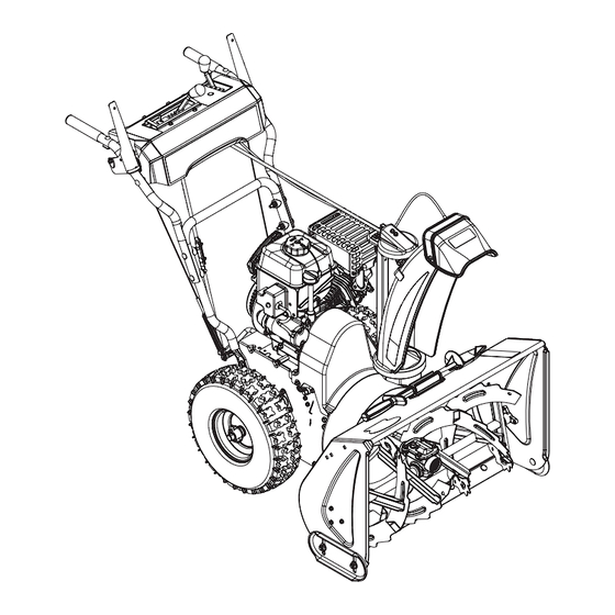
Page 10: Controls & Features
CONTROLS & FEATURES 16 18 Figure 3 1. Engine Key 15. Attachment Clutch Lever 2. Engine Run / Stop Switch 16. Traction Drive Clutch Lever 3. Primer Bulb 17. Discharge Chute Rotation Lever 4. Fuel Tank and Cap 18. Discharge Chute Deflector Lever 5. -
Page 11: Engine Key And Run / Stop Switch
CHOKE CONTROL KNOB WARNING: Read and See Figure 6. understand the Safety section Controls airflow to the engine. before proceeding. See Figure 3 for all controls and features locations. ENGINE KEY AND RUN / STOP SWITCH See Figure 4. Figure 6 The removable engine key and the run / stop switch are used together to start the engine. -
Page 12: Traction Drive Clutch Lever (Left Side)
TRACTION DRIVE CLUTCH LEVER (LEFT SIDE) See Figure 9. Allows unit to travel forward and in reverse. Figure 11 Figure 9 SCRAPER BLADE DUAL HANDLE INTERLOCK Contacts the surface being cleared and protects the housing from damage during Allows auger / impeller to rotate without normal use. -
Page 13: Start The Engine
NOTICE: Stop auger when traveling between E30 / E85 compatible. The maximum work areas. recommended ethanol content is 10%. Ariens recommends using a quality fuel stabilizer in 4. Engage traction drive clutch. all fuel. See Short Term on page 23. -
Page 14: Stop The Engine
MAINTENANCE WARNING: Read and understand the Safety section before proceeding. Your Ariens dealer can provide service and adjustments to keep your unit operating at Wheel Locked for peak efficiency. Contact an authorized engine Traction manufacturer’s service center for engine service. -
Page 15: Maintenance Schedule
** Refer to engine manual for instructions. Keep tires inflated to pressure listed on tire sidewall. SERVICE PARTS WARNING: AVOID INJURY. See your Ariens dealer to purchase service Explosive separation of tire and parts for your unit. rim parts is possible. Description Part No. -
Page 16: Lubricate Unit
(1.6 – 1.9") from the flat surface of the gearcase cover. IMPORTANT: Ariens recommends using only Ariens L3 synthetic severe duty gear lube (see Service Parts on page 13). Using other lubricants will not automatically void unit warranty, but the warranty will not cover... -
Page 17: Auger Shaft
Figure 18 Figure 17 4. Tighten skid shoe hardware. REPLACE SHEAR BOLTS ADJUSTMENTS IMPORTANT: Ariens recommends using only Ariens OEM shear bolts when replacing WARNING: AVOID INJURY. shear bolts. Read and understand the Safety See Figure 19. section before proceeding. -
Page 18: Lever
2. Adjust nuts on chute cable. See Figure 21. • To adjust deflector lower, loosen lower nut and tighten upper nut. • To adjust deflector higher, loosen upper nut and tighten lower nut. Figure 19 ADJUST DISCHARGE CHUTE DEFLECTOR LEVER 1. -
Page 19: Adjust Speed Selector Lever
ADJUST SPEED SELECTOR ADJUST ATTACHMENT CLUTCH LEVER & BRAKE See Figure 23. WARNING: AVOID INJURY. 1. Disconnect adjustment pivot pin from Improper adjustment could speed selector arm. Save hardware for result in unexpected movement reinstallation. of auger and impeller causing 2. - Page 20 5. With the attachment clutch disengaged, make sure auger idler arm lightly touches the frame. See Figure 25. Measure here. Figure 26 • If roller is 12.7 – 22.2 mm (1/2 – 7/8") from frame, no further adjustment is Check position here. required.
-
Page 21: Adjust Traction Drive Clutch
Check Attachment Brake With the attachment clutch disengaged, brake pad must contact attachment belt or pulley, whichever is closest. With attachment clutch engaged, brake pad must be a minimum of 1.6 mm (1/16") from belt or pulley. • If there is less than 1.6 mm (1/16") gap, loosen idler adjustment nut and move idler away from belt or pulley. - Page 22 4. With traction clutch disengaged, check that swing gate tab touches the front edge of stop hole. See Figure 31. IMPORTANT: Swing gate tab MUST touch stop hole edge. Readjust cable as necessary until tab touches stop hole. 1. Swing Gate Tab 2.
-
Page 23: Troubleshooting
(flooded). and reattempt starting. See Start The Engine on page 11. Engine is faulty. See your Ariens dealer or authorized engine manufacturer’s service center. Fuel mixture is too rich. Turn choke control knob to off position. See Start The Engine on page 11. - Page 24 TROUBLESHOOTING Problem Probable Cause Correction Shear bolts are broken. See Replace Shear bolts on page 15. Attachment clutch / brake is not See Adjust Attachment Clutch & Brake on adjusted correctly. page 17. Impeller is frozen in place. Move unit to a warm place to thaw. Ice or debris is obstructing auger.
-
Page 25: Storage
ACCESSORIES specifications. 3. Inspect unit for visible signs of wear or damage. Repair as needed. See your Ariens dealer for a complete list of compatible accessories and attachments for 4. Apply a light layer of oil or anti-rust your unit. -
Page 26: Specifications
SPECIFICATIONS Model Number 920402 Description Sno-Tek 24E Engine Sno-Tek 208 Gross Torque* – N•m (lb-ft) 12.9 (9.5) 208 (12.7) Displacement – cm Maximum RPM – No load 3600 ± 100 Electric Start 120V Fuel Tank Capacity – liter (qt) 2.7 (2.9) -
Page 27: Warranty
, Sno-Tek ® and Chore Performing Equipment Limited Warranty Warranty Ariens Company (Ariens) warrants to the original purchaser that Ariens, Gravely, Parker, and Countax ® ® brand chore performing equipment (including Sno-Thro and Sno-Tek equipment) purchased on or after 1/1/2015 will be free from defects in material and workmanship for the time period noted in the chart below. - Page 28 Register the product immediately at the time of sale. If the dealer does not register the product, the customer must complete the product registration card in the literature package and return it to Ariens Company, or register the unit online at www.ariens.com, www.gravely.com, www.countax.com or www.parkersweeper.com.
- Page 29 Exclusions – Items Not Covered by This Warranty • Parts that are not genuine Ariens, Gravely, Parker or Countax service parts are not covered by this warranty and may void the warranty. • Damages resulting from the installation or use of any part, accessory, or attachment which is not approved by the Ariens Company for use with product(s) identified herein are not covered by this warranty.
- Page 30 Ariens Company 655 West Ryan Street Brillion, WI 54110 ariensstore.com ariens.custhelp.com parts.ariens.com...
Need help?
Do you have a question about the Sno-Tek 24E and is the answer not in the manual?
Questions and answers
does the Sno-Tek snow blower have a spARK PLUG?
I need to buy the spark plug with the tool to ope it for my Sno-Tek Areina 24
Yes, the Ariens Sno-Tek snow blower with part number 24E has a spark plug.
This answer is automatically generated
I want to buy the spark plug and the tool to op it for my Sno-tek arina 24