Ariens Sno-Thro 921001 – ST824E Owner's/Operator's Manual
Hide thumbs
Also See for Sno-Thro 921001 – ST824E:
- Owner's/operator's manual (42 pages) ,
- Parts manual (28 pages)

Related Manuals for Ariens Sno-Thro 921001 – ST824E


Summary of Contents for Ariens Sno-Thro 921001 – ST824E
- Page 1 Sno-Thro ® Owner/Operator Manual Models 921001 – ST824E 921002 – ST1027LE 921003 – ST1130DLE 921004 – ST924DLE ENGLISH FRANÇAIS 00660400 6/07 Printed in USA...
-
Page 2: Table Of Contents
PRODUCT REGISTRATION damage. The contents will provide you with safety The Ariens dealer must register the product at the time instructions for the safe use of your unit during normal of purchase. Registering the product will help the operation and maintenance. -
Page 3: Safety
Ariens Dealer for assistance. Make sure controls function as described in this manual. all assembly has been properly completed. 4. Review recommended lubrication, maintenance NOTE: To locate your nearest Ariens Dealer, go to and adjustments. www.ariens.com on the Internet. 5. Review Limited Warranty Policy. -
Page 4: Safety Rules
SAFETY DECALS AND LOCATIONS Stop engine, remove key, read manual ALWAYS replace missing or damaged Safety Decals. before making any repairs or Refer to figures below for Safety Decal locations. adjustments. OL4010 921002, 003, 004 Wear appropriate hearing protection. OL4690 08000134 ONLY use clean-out tool to clear blockages. - Page 5 ALWAYS check overhead and side clearances DO NOT throw snow any higher than necessary. carefully before operation. ALWAYS be aware of traffic Deflected materials can cause injury and property when operating along streets or curbs. damage. Keep children and people away. Keep children out of Always stand clear of the discharge area when work area and under watchful care of a responsible operating this unit.
- Page 6 Never carry passengers. Before tipping unit up onto housing, remove fuel so no spills will occur. Ensure unit is secure and will not tip Check clutch and brake operation frequently. Adjust over during maintenance. and service as required. All motion of drive wheels and auger/impeller must stop quickly when control levers ALWAYS keep protective structures, guards, and are released.
-
Page 7: Assembly
ASSEMBLY 921001 WARNING: AVOID INJURY. Read and understand the entire Safety section before proceeding. WARNING: Dropping or tipping over boxed unit could result in personal injury or damage to unit. PACKAGE CONTENTS 921002, 003, 004 1. Sno-Thro Unit 3. Chute Rod 2. - Page 8 NOTE: Leave discharge chute pedestal loose to help 921001 install the chute rod and connect it to the control assembly. 1. Handlebar 3. Wing Nuts and Bolts 2. Wing Knobs and Bolts 4. Speed Selector Lever Figure 6 OS7032 921002, 003, 2, 3 1.
- Page 9 NOTE: After the chute rod has been inserted through 11. Tighten pedestal hardware to 15 – 31 lbf-ft (20 – the hex hole in the control assembly, placing the unit in 42 N•m). the service position (see Service Position on page 18) 12.
- Page 10 2. Insert the barrel on the cable end into the bracket CAUTION: Avoid injury! Explosive separation on left side of chute deflector (Figure 12). of tire and rim parts is possible when they are 3. Hold seal out of the way while routing the cable serviced incorrectly: through the bracket on the left side of the •...
-
Page 11: Controls And Features
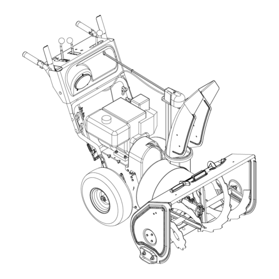
CONTROLS AND FEATURES 1. Attachment Clutch Lever 921001 2. Speed Selector 3. Traction Drive Clutch Lever 4. Chute Control 5. Oil Fill/Dipstick 6. Discharge Chute Deflector 7. Discharge Chute 8. Impeller 9. Clean-Out Tool 10. Auger 11. Scraper Blade 12. Auger Gearcase 13. - Page 12 1. Attachment Clutch Lever 2. Speed Selector 921002, 003, 004 3. Deflector Remote Control 4. Chute Control 5. Traction Drive Clutch Lever 6. Oil Fill/Dipstick 7. Discharge Chute Deflector 8. Discharge Chute 9. Impeller 10. Clean-Out Tool 11. Auger 12. Auger Gearcase 13.
-
Page 13: Operation
OPERATION Ignition Switch (Push/Pull Safety Key) WARNING: AVOID INJURY. Read and understand the entire Safety section before Key Switch has two positions: proceeding. 1. “Stop” - pulled out 2. "Run" - pushed in WARNING: To avoid injury to hands and feet, always disengage clutches, shut off engine, NOTE: DO NOT twist key after it is and wait for all movement to stop before... - Page 14 Choke Control Knob 3. Remove the snow clean-out tool (1) from the auger housing and use it to remove the clog from 1.Choke Closed position: the discharge chute. chokes off air to engine for 4. Replace the snow clean-out tool on the auger easier start.
- Page 15 Discharge Chute Control (921002, 003, 004) Remote Wheel Lock (921002) IMPORTANT: If chute does not stay in set position, Squeeze and release the remote wheel lock to lock the adjust as directed in SERVICE AND ADJUSTMENTS left wheel for better traction when throwing snow or to on page 21, or repair before operation.
-
Page 16: Filling Fuel Tank
FILLING FUEL TANK 3. If Impeller is frozen, (cannot pull Starter Handle) move unit to a heated area and thaw to prevent possible damage. WARNING: AVOID INJURY. Read and understand the entire Safety section before 2. Check Function of Clutches proceeding. -
Page 17: Snow Removal
STARTING AND SHUT OFF 5. Push Primer Bulb 2 or 3 times for cold engine. NOTE: When temperature is below -15° F (-26° C) WARNING: FAILURE TO FOLLOW additional priming may be needed. INSTRUCTIONS could result in personal 6. Insert key into ignition switch on engine and push injury and/or damage to unit. -
Page 18: Maintenance
DO NOT transport machine while engine is running. MAINTENANCE Ariens Dealers will provide any service or adjustments MAINTENANCE SCHEDULE which may be required to keep your unit operating at peak efficiency. Should engine service be required,... -
Page 19: General Lubrication
Keep tires at pressure listed on the tire sidewall. See Check Tire Pressure on page 10. NOTE: Apply Ariens Hi-Temp Grease or equivalent to the lubrication fittings. See SERVICE PARTS on CHECK AUGER GEARCASE page 29. - Page 20 921002, 003, 004 921002 921003, 004 921001 Grease OS7136 OS7141 OS7142 OS7143 Figure 23 GB - 20...
-
Page 21: Service And Adjustments
Figure 24 Dealer for repairs. SHEAR BOLTS IMPORTANT: Use only Ariens shear bolts for replacement. Use of any other type of shear bolt may result in severe damage to unit. See SERVICE PARTS on page 29. - Page 22 921002, 003, 004 Tighten nut. No Slack 1. Top Jam Nut 2. Bottom Jam Nut 3. Cable Adjuster Figure 26 OS7170 DEFLECTOR REMOTE (921002, 003, 004) Deflector must stay in selected position while throwing 1. Adjusting Nuts snow. 2. Cable Support Bracket If deflector does not stay in set position: Figure 27 OS7175...
-
Page 23: Discharge Chute Deflector
If chute does not rotate freely: 921001 Tighten the cable by loosening the upper adjustment nut, and then tightening the lower adjustment nut against the bracket (Figure 29). 921002, 003, 004 Loosen upper adjustment nut. Tighten lower adjustment nut. Figure 29 OS7180 1. - Page 24 3. With the attachment clutch disengaged, check that the attachment idler arm lightly touches the frame. See Figure 34. With the attachment clutch disengaged, check the attachment idler arm position here. The attachment idler arm should lightly touch the frame. 1.
- Page 25 1/2 – 9/16 in. (12.7 –- 14.3 mm) OS7183 OS7184 Figure 36 2. Adjust attachment idler position. See Figure 37. Roller should be a minimum of 1/2 in. (12.7 mm) a. Loosen idler adjustment nut. from the frame when the attachment clutch is b.
-
Page 26: Traction Drive Clutch Adjustment
Check Attachment Brake Check belt finger clearance here. With the See Figure 38. attachment clutch engaged, there should be 1. With the clutch lever disengaged, brake pad must less than 1/8 in. (3 mm) clearance between the contact attachment belts. With clutch lever belts and the belt finger. -
Page 27: Attachment Drive Belt
b. Turn the adjuster body up the cable to 3. Rotate discharge chute all the way to the left (as decrease the distance between the clutch viewed from the operator’s position). lever and handlebar. 4. 921002, 003, 004: Remove hair pin under the c. -
Page 28: Traction Drive Belt Replacement
2. Tip housing and frame back together and secure with hex bolts. 3. Place belt onto engine sheave. 4. Reposition and secure belt fingers. IMPORTANT: With clutch lever engaged, belt finger on the side opposite the belt idler should be less than 1/8 in. -
Page 29: Storage
00170800 Friction Disc OS7142 52100100 Shear Bolt Kit STORAGE ACCESSORIES See your authorized Ariens dealer to add the additional accessories available to your Sno-Thro. WARNING: AVOID INJURY. Read and Part No. Description understand the entire Safety section before proceeding. 72406500... -
Page 30: Troubleshooting
TROUBLESHOOTING PROBLEM PROBABLE CAUSE CORRECTION 1. Fuel tank is empty. 1. Fill fuel tank. Engine will not crank/start. 2. Fuel shut-off valve closed. 2. Open fuel shut-off valve. 3. Build up of dirt and residue around 3. Clean area around governor/carburetor. governor/carburetor. -
Page 31: Specifications
SPECIFICATIONS Model Number 921001 921002 921003 921004 Description ST824E ST1027LE ST1130DLE ST924DLE Engine - Tecumseh Tecumseh Tecumseh Tecumseh LH318SA LH358SA LH358SA LH318SA Power Max - HP (kW) 8.0 (5.97) 10.0 (7.46) 11.0 (8.20) 9.25 (6.90) Fast Idle Speed - RPM (min 3600 ±... -
Page 32: Warranty
1000 hours of use, whichever comes material and workmanship for ninety (90) days following the first, if any product is rented or leased. date of purchase. Ariens Company • 655 W. Ryan St. • Brillion, WI 54110-1072• (920) 756-2141 • www.ariens.com ALW2 - 62207... - Page 33 (12) months after the date of purchase. Ariens may from time to time change the design of its products. Nothing contained in this warranty shall be construed as obligating Ariens to incorporate such design changes into previously manufactured products, nor shall such changes be construed as an admission that previous designs were defective.
- Page 34 Ariens Company 655 West Ryan Street Brillion, WI 54110-1072 920-756-2141 Fax 920-756-2407 www.ariens.com...
Need help?
Do you have a question about the Sno-Thro 921001 – ST824E and is the answer not in the manual?
Questions and answers