Table of Contents
Advertisement
Quick Links
Advertisement
Table of Contents

Related Manuals for Salutron HardyTest HARTIP 1800


Summary of Contents for Salutron HardyTest HARTIP 1800
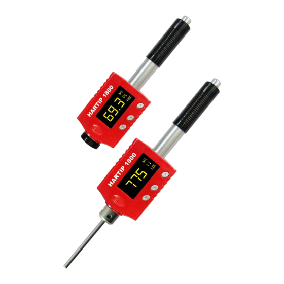
- Page 1 HARDNESS TESTER HardyTest HARTIP 1800 OPERATION MANUAL...
-
Page 3: Table Of Contents
CONTENTS FOREWORDS ............................2 1.1............................... 2 ISTORY 1.2. ) ........................2 ARDNESS DEFINITION 1.3. ’ ........................2 OTATION OF ARDNESS FEATURES AND APPLICATIONS ........................ 3 2.1.............................. 3 NTRODUCTION 2.2............................. 3 PECIFICATIONS 2.3............................... 4 EATURES 2.4............................... 4 PPLICATIONS LAYOUT OF INSTRUMENT ........................ -
Page 4: Forewords
Forewords 1.1. History The Leeb measuring method was first brought into measurement technology in 1978. It is defined as the quotient of an impact body’s rebound velocity over its impact velocity, multiplied by 1000. Harder materials produce a higher rebound velocity than softer materials. -
Page 5: Features And Applications
For example: Hardness HRC converted from hardness L using impact device D should be written as 35, 9 HRCLD. Where: 35=Hardness value HL 9=Hardness value HRC L=Leeb’s Method D=Impact device Features and Applications 2.1. Introduction This instrument is an advanced state-of-the-art palm sized metal hardness tester with many new features which are light weight, easy operation, integrated design, high contrast display, low operating temperature, auto compensating for impact direction and etc. -
Page 6: Key Features
2.3. Key Features High accuracy: 0.3% Integrated design: combine probe and processor into one unit Two-in-one probe: D-DL convertible Wide operating environment: -40 º C ~+70 º C Auto turn on & off High contrast OLED display: clearing at dark area ... -
Page 7: Symbols And Illustrations
Symbols and Illustrations 4.1. Symbols and Illustrations Symbols Illustrations Leeb hardness value used with impact device D Leeb hardness value used with impact device DL Brinell hardness value Rockwell B hardness value Rockwell C hardness value Shore hardness value Vickers hardness value Rockwell A hardness value σb (N/mm2) Strength value... -
Page 8: Preparation Before Measuring
Preparation before Measuring 5.1. Requirements for the sample 5.1.1. The surface temperature of sample should be less than 120 C. 5.1.2. The samples must feature a metallic smooth, ground surface, in order to eliminate erroneous measurements brought about by coarse grinding or lathe scoring. The roughness of the finished surface should not exceed 2μm. -
Page 9: Surface Of The Test Sample Should Not Be Magnetic
with impact device D/DL the depth of the hardened layer should be no less than 0.8 mm. 5.4. Surface of the test sample should not be magnetic. 5.5. For test sample of curving surface with radius of curvature R less than 30mm, a small support ring should be used. -
Page 10: Operation
Operation Figure 6-1 Display Description 6.1. Button description ▼:Downward button: Move cursor downward or horizontal. In measuring mode, shift single or duplex display mode or start to print a new page while Bluetooth printing is on. Delete current reading after set up statistics. ▲:Upward button: ... -
Page 11: Diagram Of Operation
6.2. Diagram of Operation Figure 6-2 Diagram of Operation... -
Page 12: Power On The Instrument
6.3. Power on the instrument This tester has the function of auto power on while taking measurement and auto power off after approx one minute of non-use. To switch on the tester, push the loading tube toward tester until locking the impact body inside the probe. - Page 13 Change value or digit circulative from 0 to 9. Shift normal or upright display mode. ►:Confirmation button: Enter main menu. Confirm the selected item. ▼&▲:Press downward and upward button simultaneously: In measuring mode, turn off Bluetooth connection. 6.4.2.
- Page 14 Figure 6-9 Materials Menu 6.4.4. Hardness scale conversion Choose Hardness scale from parameters menu and press ► button to enter sub-menu. Press▼ or ▲ button to choose different hardness scales, then press ► button to confirm the selection and return to parameters menu. Different hardness scales will show on the screen depending on different materials.
-
Page 15: Statistics Setup
6.5. Statistics setup Choose Statistics from main menu and press ► button to enter statistics menu. Press ▼ or▲ button to choose the option to be set. Once the option is chosen, press ► button to confirm this selection. Figure 6-12 Statistics Menu 6.5.1. -
Page 16: Memory Setup
6.5.2. Delete measured values After mean time is set, in order to avoid the error caused by abnormal values involving in calculation, you can delete the current values by following operation. Enter the upright display mode, and then press ▼ key to delete current measuring value. All measured values from this time to NO 01 can be deleted one by one. - Page 17 6.6.1. Memory on/off Choose Memory on/off from memory menu and press ► button to enter sub-menu. Press▼ or ▲ button to choose the option to be set and press ► button to confirm the option. Figure 6-19 Memory on/off Menu Off: If this option is chosen, the instrument will not store measured values.
- Page 18 6.6.2. Data recall Choose Data recall from Memory menu and press ► button to enter the block no. selection window. All blocks stored in the instrument are showed on the window; at most 9 block numbers are showed on each screen. “Change Page” is showed on upper left corner.
-
Page 19: Data Transfer
6.7. Data Transfer Choose Data Transfer from main menu and press ► button to enter Data Transfer menu. Figure 6-22 Data Transfer 6.7.1. Select port Choose Select port from Data transfer menu and press ► button to enter Select port menu. -
Page 20: Function Setup
Bluetooth connection. Run software from PC or power on the micro-printer. (See 10.2 for micro printer operations) Taking measurement and the data will be downloaded to PC or be printed one by one. Note: Please make sure the connection between PC and tester is successful. (See 11.3.2) Under Bluetooth printing/communication mode, the first measurement is for active Bluetooth communication, this test value might not be displayed, it is normal. - Page 21 6.8.1. Display mode Figure 6-28 Display View Menu This tester is designed to display corresponding two values on the screen when you set up all other hardness scales except HLD. For example: when you select HRC as hardness scale, the screen can be set to display HRC value and also its correspondent HLD value. Figure 6-29 Duplex display By pressing ▼...
- Page 22 Figure 6-31 Downward / Upward View 6.8.4. Operation of display view Press related buttons to enter main menu. 6.8.5. Select Function Setup and press ► button to enter its sub-menu. Select Display view, press ► button to enter it. Select the display view you wanted and then press ► button to confirm. 6.8.6.
- Page 23 Figure 6-33 Calibration Pressing button ▼, cursor will move between 7 6 0 and Back, the standard value can be changed from 0 to 9 by pressing ▲ button. After setting standard block value, press ► button to enter next step. Moving cursor to Back and press ►...
-
Page 24: Changing Impact Body
Materials: M1 Mean time: 0 time Upper limit alarm: 999 (HLD) Lower limit alarm: 150 (HLD) Memory: off Display view: normal Changing impact body This tester has a very unique feature, which impact device can convert between D and DL simply by changing impact body. -
Page 25: Take Measurement
8.1.2. Push the loading tube with a little force against spring force toward tester until to lock the impact body. Figure 8-2 8.1.3. Loose the force and let the loading tube returns to the original position. 8.2. Take measurement Place the tester against onto the surface of object to be measured by the support ring. As figure 8-3. -
Page 26: Maintenance And Repair
When a battery indicator displays that reminds you to charge the battery. However it is still possible to measure for some time. Please make sure to obtain additional or replacing battery from SALUTRON. Otherwise it may cause the instrument to get un-accuracy value. -
Page 27: System Reset
measuring mode by pressing any key. Please make sure to keep the instrument in measuring mode during charging, otherwise it will stay in that screen instead of entering screen saver mode. 9.3. System reset The instrument doesn’t response possibly due to instable power voltage or others, the instrument can be reset when it does not response. -
Page 28: Optional Accessories
10. Optional Accessories 10.1. Support Rings and impact body Support Rings for Impact Device D Part designation and dimensions: Suitable for the following surfaces Φ 19.5×5.5mm R≥60mm plane cylindrical hollow-cylindrical spherical hollow-spherical Φ 13.5×5.5mm R≥30mm plane cylindrical hollow -cylindrical spherical hollow-spherical Special Support Rings Cylindrical... - Page 29 10.2.3. Feeding Paper Press the paper feed button (right button), the printer start feeding paper. If release the button, then stop feeding paper. 10.2.4. Self-test In the power-off state, press the paper feed button (right panel), do not release, and then power on.
-
Page 30: Pc Software
11. PC Software 11.1. Installation of hardware driver As the tester is connected with the PC for the first time, the Windows operating system will prompt “found new hardware”. Then select the folder for the hardware driver manually. Folder: (x: \ is the Drive Letter of the application CD) x:\ cp2102\Drivers\CP210x USB Composite Device x:\ cp2102\Drivers\CP210x USB to UART Bridge Controller Install these two drivers. -
Page 31: Operation Of Pc Software
After installation completes, click “Close” to quit the Setup Wizard. A program icon will be created on the desktop automatically. Note: If it is displaying that the “.Net Framework” is not installed during installation, install the file NET35_SP1_cn.exe that is located in X:\ dotnet_35 folder in the CD. You can also download it from the Microsoft website. - Page 32 11.3.1. Introduction of the main interface 11.3.2. Create commnunication between the tester and PC Before the transmission starts between hardness tester and PC, a RS232 communication should be created between them. 1) Connect the tester and PC with the USB cable supplied with the tester. 2) Power on the tester.
- Page 33 button ”Edit” to active all input fields; input the information; to save the data, press ”OK” , then system will prompt “User information is written successfully!”. The user’s information will be saved. 11.3.4. Test data Click “Test data” tab in the working area or click button from the tool bar to load the Test data working area.
- Page 34 File Save ( ) – to save current test data. After finish testing, select Save from the File menu or click button, Save dialog box will display, input the file name and click “Save”, your data will be saved into a Microsoft Excel document.
- Page 35 Note: Setting mean time will load a new test form automatically, so you need to save your current measuring data before select mean time button. Save and Print functions can’t be used when the mean time isn’t 0. 11.3.5. Parameter In Parameter screen, click “Read”...
- Page 36 11.3.7. Calibration After long time of use, the ball tip on impact body may worn which would lead inaccuracy. In order to compensate such error, the tester is designed to re-calibrate by user. You can also do calibration from the tester’s menu (Please refer to 6.8.9). 1) Setting the value of standard block for calibration To modify the value of standard block, input the real value of standard block in the standard value box and press “Change standard value”.
- Page 37 Stored data screen In Stored data window, click button in the toolbar will create a new form. Click button to open saved stored data. Click button to read stored data. Click button to save current data into Microsoft Excel document. Click button to print current data to the default printer.
-
Page 38: Quit The Program
11.4. Quit the program After finish all the job, you can click from the tool bar to quit the program. - Page 40 Dr.-Got · D -5 Frechen Tel. +49 (0) 2234 9999960 · Fax. +49 (0) 2234 9999962 Email: info@salutron.de · www.salutron.de...
Need help?
Do you have a question about the HardyTest HARTIP 1800 and is the answer not in the manual?
Questions and answers