Table of Contents
Advertisement
Quick Links
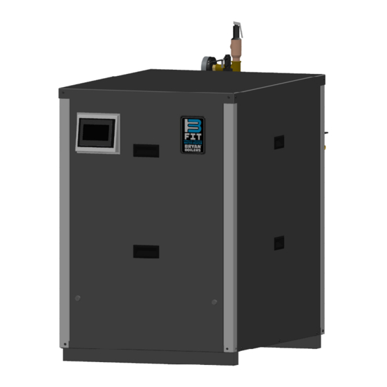
Condensing with the Power to FIT
INSTALLATION, OPERATION, AND
MAINTENANCE MANUAL
400-1000 MBH Hot Water Boiler Indoor/Outdoor
Boiler Model:
Installation Date:
Heating Contractor:
Address:
Bryan Steam, LLC
Phone: 765-473-6651
Boiler Models
BFIT 400
BFIT 500
BFIT 650
BFIT 800
BFIT 1000L
783 N. Chili Avenue, Peru, IN 46970
WARNING: If the information in these
instructions is not followed exactly, a fire
or explosion may result causing property
damage, personal injury or death.
Do not store or use gasoline or other
flammable vapors and liquids in the vicinity
of this or any other appliance.
WHAT TO DO IF YOU SMELL GAS
• Do not try to light any appliance.
• Do not touch any electrical switch; do
not use any phone in your building.
• Immediately call your gas supplier
from a neighbor's phone. Follow the
gas supplier's instructions.
• If you cannot reach your gas supplier,
call the fire department.
Installation and service must be performed
by a qualified installer, service agency or the
gas supplier.
Serial Number:
System Type:
Phone/Email:
PN: 110820-06
Rev. 0
Save this manual for future reference.
www.bryanboilers.com
inquiry@bryansteam.com
Advertisement
Chapters
Table of Contents

Related Manuals for Bryan Boilers BFIT 400


Summary of Contents for Bryan Boilers BFIT 400
- Page 1 • Immediately call your gas supplier from a neighbor’s phone. Follow the gas supplier’s instructions. Boiler Models • If you cannot reach your gas supplier, BFIT 400 call the fire department. BFIT 500 Installation and service must be performed BFIT 650...
-
Page 2: Table Of Contents
VII. Venting Venting Design Requirements Field Installation Room Air for Combustion PVC Venting Venting for Outdoor Installation General Termination Vent and Combustion Air Terminations Multiple Appliance Terminations Terminal Installation Polypropylene Venting Optional Room Air for Combustion Removing Existing Appliance Special Installation Requirements for Massachusetts Condensate trap VIII. Condensate Disposal BFIT 400-1000L I&O Manual... - Page 3 Check Thermostat Operation Adjust Supply Water Temperature Testing of Controls and Safety Devices General Maintenance XIV. Service and Maintenance Monthly Inspection Annual Inspections and Service Restarting after Prolong Shutdown Troubleshooting APPENDIX A: Tables APPENDIX B: Figures APPENDIX C: Default Light-off and Modulation Rates BFIT 400-1000L I&O Manual...
-
Page 4: Hazard Definitions
(gas valve, blower, etc.). correctly installed and are operating properly. 2. Factory warranty does not apply to units improperly installed or improperly operated. BFIT 400-1000L I&O Manual... -
Page 5: Appliance Operation
California to cause cancer and birth defects or other reproductive harm. For more information go to: www. P65Warnings.ca.gov. Should overheating occur or the gas supply fail to shut off, turn off the manual gas control valve to the appliance. BFIT 400-1000L I&O Manual... -
Page 6: Product Rating, Specifications, And Dimensional Data
Appliance will go into hard lockout if temperature exceeds 200 Table 3: Appliance Connection Sizes BFIT Model Dimensions (in.) 1000L Gas Inlet Water Outlet Pipe (FNPT) Water Inlet Pipe (MNPT) Air Intake Vent Outlet Condensate Drain (PVC) Drain Line (FNPT) Electrical Conduit Holes BFIT 400-1000L I&O Manual... - Page 7 8 " 8 " 43" 2 " 2 " 8 " 4 " 2 " 4 " 4 " 8 " 8 " 8 " 4 " Front View Rear View 10" Figure 1: BFIT 400-500 Dimensions BFIT 400-1000L I&O Manual...
- Page 8 8 " 4 " 43" 2 " 8 " 2 " 4 " 26 2 " 4 " 4 " 8 " 8 " 4 " 8 " Front View 10" Back View Figure 2: BFIT 650-1000L Dimensions BFIT 400-1000L I&O Manual...
-
Page 9: Unpacking The Bfit
Please read the instructions contained in this manual carefully as they provide important information regarding the safe installation, use and servicing of this appliance. Rear intake cover Figure 3: LBFIT with Outdoor Trim BFIT 400-1000L I&O Manual... -
Page 10: Bfit Water Heater Component Identification
4" female PVC slip provided for 400-500 models. 15. Gas supply connection 6" aluminum ring provided for 650-1000 models. Connection to appliance gas train. See Table 28 for model specific pipe sizes. 16. Inlet/Return 2" Male NPT inlet water connection to the appliance. BFIT 400-1000L I&O Manual... - Page 11 V. BFIT Water Heater Component Identification (continued) Figure 4: Component Identification BFIT 400-1000L I&O Manual...
-
Page 12: Pre-Installation And Mounting
Ensure all labels on the product are fully visible cause leakage of flue gas from the venting system. at all times for the purpose of maintenance and inspections. BFIT 400-1000L I&O Manual... -
Page 13: Appliance Mounting
Do not install this appliance under an overhang heat exchanger. less than 3 feet from its top. The area under the 4. Provide adequate space for condensate piping, overhang must be open on 3 sides. condensate pump, or neutralizer kit. BFIT 400-1000L I&O Manual... -
Page 14: Bfit 400-1000L Stacking
VI. Pre-Installation and Mounting (continued) D. BFIT 400-1000L Stacking 3. Outdoor BFIT models cannot be stacked. 1. The BFIT 400-1000L models may be installed in a 4. The display bracket on the top appliance can be stacked configuation. rotated for a better viewing angle of the Concert a. -
Page 15: Clearances
3. Follow vent material manufacturer for vent clearances. 4. Clearances for closet or alcove Installation: Front - 24" Sides - 24" Rear - 22" Top - 20" Table 5: BFIT 400-1000L Clearances 24 in Minimum Front Rear Right Left Clearance (In.) -
Page 16: General Venting Guidelines
2. Equivalent length method: Do not exceed system can be designed to ensure the reliability of maximum vent/combustion air lengths listed in the appliance(s). Table 6. Equivalent lengths of fittings are given in Table 7. BFIT 400-1000L I&O Manual... -
Page 17: Field Installation
Combustion Air Total Vent Total Equivalent Length Equivalent Length Notes: 1. Total equivalent length cannot exceed maximum equivalent length shown in Table 6. 2. Combustion air and vent terminations do not count towards total equivalent length. BFIT 400-1000L I&O Manual... - Page 18 Note: Flow rates are based on the combustion of natural gas. Use of cellular core PVC (ASTM F891), cellular core CPVC, or Radel® (polyphe- NOTICE NOTICE nylsulfone) in non-metallic venting systems is prohibited. Covering non-metallic vent pipe and fittings with thermal insulation is prohibited. BFIT 400-1000L I&O Manual...
-
Page 19: Room Air For Combustion
The outdoor vent system requires field installed support. Do not rely on the vent adapter of the appliance to hold the vent material The outdoor vent kit may be shipped separately from the appliance. BFIT 400-1000L I&O Manual... -
Page 20: General Termination
Notes: 1. It is recommended to use tees for both intake and vent terminations in extra windy locations. 2. All terminations shall have bird screens. 3. All non-metallic venting exposed to sunlight shall be UV resistant. BFIT 400-1000L I&O Manual... - Page 21 Covering non-metallic vent pipe and fittings with through a common conduit or chase so that thermal insulation is prohibited. one roof penetration may be made. Maintain recommended separations of terminations after penetration. Figure 8: Vent Terminal Clearances BFIT 400-1000L I&O Manual...
- Page 22 In accordance with the current CSA B149.1, Natural Gas and Propane Installation Code In accordance with the current ANSI Z223.1/NFPA 54, National Fuel Gas Code If locally adopted installation codes specify clearances different than those illustrated, then the most stringent clearance shall prevail. BFIT 400-1000L I&O Manual...
- Page 23 In accordance with the current CSA B149.1, Natural Gas and Propane Installation Code In accordance with the current ANSI Z223.1/NFPA 54, National Fuel Gas Code If locally adopted installation codes specify clearances different than those illustrated, then the most stringent clearance shall prevail. BFIT 400-1000L I&O Manual...
-
Page 24: Vent And Combustion Air Terminations
Do not use a barometric damper or draft hood bustion air terminals is to prevent flue gas recir- with this appliance. culation. Recirculation of flue gas products into the combustion air supply can cause damage to property or the appliance. BFIT 400-1000L I&O Manual... - Page 25 One appliance per ducted louver or gooseneck Vent and Intake piping must not share the same ducted louver or gooseneck All terminations should have Bird/Rodent Screens Do not use rain caps, Rain will drain through boot tee or condensate drain BFIT 400-1000L I&O Manual...
- Page 26 To avoid/ minimize frost damage, extend the distance from building surfaces to vent termination end and increase the horizontal distance between adjacent vent terminations BFIT 400-1000L I&O Manual...
-
Page 27: Multiple Appliance Terminations
1/2 in. x 1/2 in. (13 mm x 13 mm) Alteration of the appliance vent connection is mesh. prohibited. 4. Adhere to the minimum and maximum wall thickness specified by the manufacturer of the wall penetration assembly. BFIT 400-1000L I&O Manual... - Page 28 4. For roof terminations, install vent terminal Above Snow Line downstream of prevailing winds relative to intake terminal. 5. It is recommended to use tee terminations with a vertical run in extra windy areas. Figure 12: Multiple Appliance Direct Vent Termination BFIT 400-1000L I&O Manual...
-
Page 29: Polypropylene Venting
The air supply requirements found in the boiler room. If contaminants cannot below are a summation of Clause 8.4 specific to be removed, do not use room air for combustion. this gas appliance. BFIT 400-1000L I&O Manual... - Page 30 Do not insulate polypropylene vent pipes. Excessive heat could cause premature vent pipe failure. Figure 13: Flexible Vent in Masonry Chimney with Separate Combustion Air Intake BFIT 400-1000L I&O Manual...
- Page 31 The final approval of all system If any of these contaminants are present, severe designs must be acceptable to the authority having corrosion and failure will result. jurisdiction. BFIT 400-1000L I&O Manual...
-
Page 32: Removing Existing Appliance
Propane Installation Code, CAN/CSA B149.1. Resizing of any portion of the common venting system, should be done in accordance with the National Fuel Gas Code, ANSI Z223.1/NFPA 54 and/ or the Natural Gas and Propane Installation Code, CAN/CSA B149.1. BFIT 400-1000L I&O Manual... -
Page 33: Special Installation Requirements For Massachusetts
5. A copy of all installation instructions for all Product Approved sidewall horizontally vented gas fueled equipment, all venting instructions, all parts lists for venting instructions, and/or all venting design instructions shall remain with the appliance or equipment at the completion of the installation. BFIT 400-1000L I&O Manual... -
Page 34: Condensate Disposal
Use continuous Teflon, high temperature silicone tubing, or other tubing material compatible with flue gas condensate for condensate piping. c. Do not route or terminate the condensate drain line in areas subject to freezing temperatures. BFIT 400-1000L I&O Manual... -
Page 35: Condensate Neutralizer Installation
2. If a common sump is used, individual drain lines 107860-09 107886-10 should be constructed, using material listed above, 107860-09 107886-10 such that one drain cannot back feed into another drain. 1000L 107860-06 107886-06 3. Do not manifold condensate and vent drains together. BFIT 400-1000L I&O Manual... -
Page 36: Hydronic Piping
2. A pressure relief valve is included and installed by factory. 3. When piping the appliance to the system, do not install an elbow closer than 5 pipe diameters from the flow switch. BFIT 400-1000L I&O Manual... - Page 37 5 pipe diameters from T & P Gauge the flow switch. 2" pipe nipple, close 2" X 2" X 1" reducing tee 3/4" pipe nipple, close 1" x 3/4" Hex Bushing Safety Relief Valve BFIT 400-1000L I&O Manual...
-
Page 38: Standard Piping Components
If the expansion tank must be replaced, consult the expansion tank manufacturer’s literature for proper sizing. BFIT 400-1000L I&O Manual... -
Page 39: Water Quality
It is recom- a. Flush the system thoroughly and repeatedly, if mended for chlorine (Cl2) levels to be below 5ppm needed. and chloride (Cl ) levels to be below 1000 ppm for 316 stainless steel. BFIT 400-1000L I&O Manual... -
Page 40: Oxygen Contamination
Table 23: Flow Rates for Glycol Systems Treatment Type Preventive Corrective System Glycol Increase Flow, Concentration (%) Producer F1 X100 X200 X300 Note: Total system water volume includes expansion tank(s) and reservoirs. X400 X500 Alphi 11 Leaker Sealer F4 Sotin 212 MC1+ BFIT 400-1000L I&O Manual... -
Page 41: Temperature Rise And Heat Exchanger Head Loss
Required Flow = Output×1000/(500×ΔT), where flow rate is in GPM, output is in MBH, and ΔT is in 0F, Outputs are shown in Table 1. This water heater has a temperature rise (delta) limit of 55 °F 400MBTU/h 500MBTU/h 650MBTU/h 800MBTU/h 1000MBTU/h Water Flow Rate (us gal/min) Figure 16: Heat exchanger water pressure loss BFIT 400-1000L I&O Manual... -
Page 42: Water Piping Diagrams
NOTICE NOTICE 3. Some piping components cannot be supported by the pipping. Refer to the manufactures' installation instructions. 4. Circulation pump must be sized to overcome the pressure drop across the entire loop. BFIT 400-1000L I&O Manual... - Page 43 3. Some piping components cannot be supported by the pipping. Refer to the manufactures' installation instructions. 4. Circulation pump must be sized to overcome the pressure drop across the entire loop. 5. Erosion could occur if common piping is undersized. BFIT 400-1000L I&O Manual...
- Page 44 3. Some piping components cannot be supported by the pipping. Refer to the manufactures' installation instructions. 4. Circulation pump must be sized to overcome the pressure drop across the entire loop. 5. Erosion could occur if common piping is undersized. BFIT 400-1000L I&O Manual...
-
Page 45: Gas Piping
For testing at 1/2 psig (3.4 kPa) or less, isolate the appliance from gas supply piping by closing the manual shutoff valve on the appliance. Figure 20: The BFIT 400-1000L Gas Connection 8. Locate leaks using approved combustible gas non- NOTICE NOTICE corrosive leak detector solution. - Page 46 0.824 22.9 11.4 ½ 1.049 29.1 14.6 ¾ 1.38 38.3 19.1 1.61 44.7 22.4 11.2 1¼ 2.067 57.4 28.7 14.4 11.5 10.3 1½ 2.469 68.5 34.3 17.1 13.7 12.3 3.068 85.2 42.6 21.3 17.1 15.3 2½ BFIT 400-1000L I&O Manual...
-
Page 47: Gas Pressure Switches
Low Gas BFIT Inlet Size (In. W.C.) (In. W.C.) Pressure Switch Pressure Switch Model (In.) (In. W.C.) (In. W.C.) Natural Propane Natural Propane Natural: 3 LP: 7 1000L Factory default high and low gas pressure switch setpoint. BFIT 400-1000L I&O Manual... -
Page 48: Electrical
1. 1. Route all field connections through conduits into Route all field connections through conduits into rors can cause improper and dangerous operation. the rear control box. the rear control box. Verify Proper operation after servicing. BFIT 400-1000L I&O Manual... -
Page 49: System And Circulation Pump Wiring
AIR DAMPER 6.3A, SLOW BLOW (IF USING 5mm X 20mm FUSE ROOM AIR) * For indirect water heating with boiler models. Use Primary Pump for direct water heating with water heater models. Figure 22: 120 VAC Connections PCB BFIT 400-1000L I&O Manual... - Page 50 XII. Electrical (continued) Figure 23: Low Voltage Connections PCB BFIT 400-1000L I&O Manual...
- Page 51 COMBUSTION AIR DAMPER AND PROVING SWITCH ARE REQUIRED IF USING ROOM AIR FOR COMBUSTION WITH MOTORIZED DAMPER(S) OR LOUVER(S). ENERGY MANAGEMENT SYSTEM WIRING CAN BE DONE WITH RJ45 PLUGS OR USING SCREW TERMINALS A, B AND C LABELED 'EMS (DELTA ONLY)'. Figure 24: BFIT 400-1000L Wire Schematic BFIT 400-1000L I&O Manual...
- Page 52 Pump L Pump N System Pump LWCO P3-12 L2-1 L2-3 P3-2 24V Transformer Figure 25: BFIT 400-1000L Wire Diagram 24V Fuse, F3 Size 400: 1.6A Slow Blow 24V Transformer Control Panel Size 500-1000: 2.4A fast acting Ground Screw P8-8 L3-1 L3-2...
- Page 53 Peer-to-Peer and EMS J8-8 Outlet/ J8-9 Supply Sensor J8-10 J9-4 Flue Gas J9-5 Sensor J9-6 J10-7 Outdoor P8-11 J10-8 Sensor P8-3 J8-11 Header/ Tank P8-9 Sensor J8-6 Remote P8-1 4-20mA J9-1 P8-2 J9-2 Sensor P8-10 Wire Diagram (continued) BFIT 400-1000L I&O Manual...
-
Page 54: System Start-Up
Concert Control is required personal injury or death. to restart. If ignition is not achieved in three consecutive attempts, contact factory or a qualified heating service technician. BFIT 400-1000L I&O Manual... - Page 55 3. Tourner la chaudière externe manuelle poignée en clapet à gaz dans le 3. Turn the external boiler manual gas valve handle clockwise sens des aiguilles d'une montre pour fermer l'offre de gaz. to close gas supply. 101607-03 Figure 26: Operating Instructions BFIT 400-1000L I&O Manual...
-
Page 56: Combustion Air/Fuel Adjustment
VALVE COIL (V2) INLET GAS PRESSURE TAP (P1) WITH INTERNAL SCREW OUTLET GAS PRESSURE TAP (P2) WITH INTERNAL SCREW GAS INLET THROTTLE SCREW OFFSET SCREW VALVE COIL (V1) (ADJUSTMENT NOT NORMALLY REQUIRED) Figure 28: BFIT 400 Gas Valve Adjustment BFIT 400-1000L I&O Manual... -
Page 57: Field Conversion Of Gas Type
111545-02 111544-02 6. Fill out the gas conversion labels included with the 111545-03 111544-03 appliance (Order part number 110301-01 if not 111545-04 111544-04 included). Follow the instructions included with the 1000L 111545-05 111544-05 label for placement. BFIT 400-1000L I&O Manual... -
Page 58: Pump Control
Low Water Level. pressing the reset button. down the main burner. Reduce the water flow rate with Water Flow Adjust manual valve to normal a manual shutoff valve until the Low Water Flow Switch position. appliance shuts down. BFIT 400-1000L I&O Manual... -
Page 59: Service And Maintenance
• If contact with skin: Wash affected area gently with soap and water. Seek immediate medical attention if irritation persists. • If breathing difficulty develops: Leave the area and move to a location with clean fresh air. Seek immediate medical attention if breathing difficulties persist. • Ingestion: Do NOT induce vomiting. Drink plenty of water. Seek immediate medical attention. BFIT 400-1000L I&O Manual... -
Page 60: General Maintenance
Wiring errors can cause installed. improper and dangerous operation. Verify proper operation after servicing. NOTICE NOTICE To reduce lime scale buildup and prolong the life of the appliance, closely monitor pH, chloride, total dissolved solids, and water hardness levels. BFIT 400-1000L I&O Manual... - Page 61 Never jump out or bypass any safety or operating control or component. Interior of the venting system must be inspected and clean before the initial startup and should be inspected periodically for any obstructions. BFIT 400-1000L I&O Manual...
- Page 62 Slide the control box out. ii. Do not spray burner, combustion chamber divider, or burner door insulations. e. The burner door, blower, and mixer assembly can be pulled out of the appliance jacket as shown in Figure 31. BFIT 400-1000L I&O Manual...
-
Page 63: Restarting After Prolong Shutdown
Control manual on how to navigate the Limit String Status screen which shows an active safety limit status and for an in-depth guide to all the possible lockouts as well as recommended corrective actions to restore operation. BFIT 400-1000L I&O Manual... -
Page 64: Appendix A: Tables
Table 14: Direct Vent Terminal Clearances Table 15: Other than Direct Vent Terminal Clearances Table 16: Table of Acceptable Terminations Table 17: Condensate Neutralizer Kit VIII. Condensate Disposal Table 18: Outlet Piping Parts IX. Hydronic Piping Table 20: Water Quality Requirements Table 19: Absolute Water Flow Rates Table 21: Corrosion/Scale Inhibitors and Removal Agents Table 22: Water Treatment Types Table 23: Flow Rates for Glycol Systems Table 24: Temperature rise, flow rate, and head loss X. Water Piping Diagrams Table 25: Maximum capacity of schedule 40 black pipe in CFH* XI. Gas Piping Table 26: Equivalent Lengths of Standard Pipe Fittings & Valves (ft) Table 27: Specific Gravity Correction Factors Table 28: Inlet Gas Pressures and Pipe Size Table 29: Electrical Ratings XII. Electrical Table 30: Combustion O Levels XIII. System Start-up Table 31: Approximate Throttle Screw Position for Gas Types Table 32: Gas Conversion Kits Table 33: Safety Device Test XIV. Service and Maintenance BFIT 400-1000L I&O Manual... -
Page 65: Appendix B: Figures
Figure 13: Flexible Vent in Masonry Chimney with Separate Combustion Air Intake Figure 14: Condensate Drain Assembly VIII. Condensate Disposal Figure 15: Relief Valve Package Assembly IX. Hydronic Piping Figure 16: Heat exchanger water pressure loss Figure 17: Single Boiler, Primary/Secondary Piping X. Water Piping Diagrams Figure 18: Multiple Boiler, Primary/Secondary with Common Header Piping Figure 19: Single Boiler with Indirect Domestic Water Heater Figure 20: The BFIT 400-1000L Gas Connection XI. Gas Piping Figure 21: High/Low Gas Pressure Switch Figure 22: 120 VAC Connections PCB XII. Electrical Figure 23: Low Voltage Connections PCB Figure 24: BFIT 400-1000L Wire Schematic Figure 25: BFIT 400-1000L Wire Diagram Figure 26: Operating Instructions XIII. System Start-up Figure 28: BFIT 400 Gas Valve Adjustment Figure 27: BFIT 500-1000L Gas Valve Adjustment Figure 29: Igniter Electrode Assembly XIV. Service and Maintenance Figure 30: Ionization Electrode (Flame Rod) Figure 31: Burner Door Opening BFIT 400-1000L I&O Manual... -
Page 66: Appendix C: Default Light-Off And Modulation Rates
1900 2400 Maximum Light-off (RPM) 3600 2600 2200 2600 2000 2600 Minimum Light-off (RPM) 3000 2200 1700 2200 1700 2200 Factory Default RPM NOTE: To maintain rate in maximum vent length application, contact factory for assistance. BFIT 400-1000L I&O Manual... - Page 67 Any damage caused by water side clogging due to dirty systems, corrosion products from the system, or improperly maintained water conditions. BFIT 400-1000L I&O Manual...
- Page 68 Bryan Steam, LLC Peru, IN 46970 Phone: 765-473-6651 Inquiry@bryansteam.com www.bryanboilers.com...
Need help?
Do you have a question about the BFIT 400 and is the answer not in the manual?
Questions and answers