Bryan Boilers AB Series Assembly Instructions Manual
Knock-down steam boiler
Hide thumbs
Also See for AB Series:
- Brochure (2 pages) ,
- Installation, operation and service manual (30 pages) ,
- Installation, operation & service manual (37 pages)

Related Manuals for Bryan Boilers AB Series


Summary of Contents for Bryan Boilers AB Series
-
Page 1: Table Of Contents
FORM 2344 4/04/2023 AB KNOCK-DOWN STEAM BOILER TABLE OF CONTENTS Description Page 1. KNOCK-DOWN TYPES AND DEFINITIONS 2. BOILER FOUNDATION 3. BOILER FRAME & TUBE INSTALLATION 4. INSULATION INSTALLATION 5. BOILER FLUE COLLECTOR INSTALLATION 6. BOILER JACKET INSTALLATION 7. FINAL ASSEMBLY 8. -
Page 2: Knock-Down Types And Definitions
FORM 2344 4/04/2023 ASSEMBLY INSTRUCTIONS BRYAN ‘KNOCKDOWN’ BOILER AB – SERIES BOLT TOGETHER STEAM BOILERS KD-1 Indicates the boiler is shipped completely assembled but constructed to be knocked down as necessary. Boiler not welded to base, to reassemble on job site. Care should be taken to observe disassembly procedure, since reassembly is exact reverse procedure. -
Page 3: Boiler Frame & Tube Installation
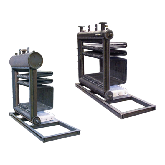
BEFORE BOILER IS SET IN PLACE CONSULT INSTALLATION, NOTICE OPERATION & MAINTENANCE MANUAL FOR PROPER CLEARANCES. 1.0 BOILER FRAME & TUBE INSTALLATION 1.1 Set boiler base assembly (Figure #1) in place on cement pad. Make sure that the base is properly positioned on the pad to Tube Rear assure the correct orientation of the... - Page 4 1.3 Shipping braces shipped loose for KD-1, used only if Pressure Vessel needed. See Figure 3. Assembly Shipping 1.4 Next place a 24” long level across the top of the Braces boiler outlet nozzle and make sure it is level on both ‘X’...
-
Page 5: Insulation Installation
1.7 (KD3 only) Next, install an inside tube (long neck down). Then install an outside boiler tube (short neck down.) Repeat this process until all boiler tubes are installed. See Figure 4. 1.8 (KD-3 only) Square up the tube bank in order to assemble flue collector ends without difficulty. 1.9 (KD-3 only) Using a 2 lb. - Page 6 2.3 Cut 1” Insulwool white blanket to tightly fit around down comers. Fold insulation to overlap a small amount around down comer. Construct insulation to come together inside combustion chamber toward front end therefore flue Collector front will hold insulation in position when bolted into place.
-
Page 7: Boiler Flue Collector Installation
3.0 BOILER FLUE COLLECTOR INSTALLATION 3.1 Arrange Flue Collector Front end onto Pressure Vessel and Base Pan Assembly. See figure 8. Do not tighten nuts until the whole flue collector is assembled with all nuts and bolts in place. 3.2 Install Flue Collector Rear end onto Pressure Vessel and Base Pan Assembly. See figure 8. Do not tighten nuts until the whole flue collector is assembled with all nuts and bolts in place. - Page 8 Fold 1” white blanket Insulation and pack on all sides of plug. Sheet metal guides Place both guides along side of plug. STEP 1 STEP 2 STEP 3 Remove all guides from plug. STEP 4 STEP 5 STEP 6 Use another sheet metal guide to drive insulation between NOTE: Repeat step 1-6 for all sides.
-
Page 9: Boiler Jacket Installation
Weld Tab Jacket Support 3.7 Assemble the jacket top supports by screwing the supports to the tabs welded on top of pressure vessel. Next, screw at least two sheet metal screws into the 10-1/2” long angles on the opposite end of jacket top support. - Page 10 4.3 Situate jacket Rear in place. The Rear End should slide over jacket Top and jacket Side. Make sure Rear is vertically level by using at least a 24” long level. Once jacket Rear is level, place one sheet metal screw in each top corner. Jacket Top Jacket Rear 4.4 Situate jacket Front in place.
-
Page 11: Final Assembly
5.0 FINAL ASSEMBLY 5.1 Install low water cut-off(s) and wire to control box. 5.2 Install heat transfer paste and low fire start aquastat sensor bulb (if provided) into immersion well. Replace retaining clops. Install any remaining wire moldings as required. 5.3 Install relief valve(s) and pipe nipple(s). -
Page 12: Connections
6.0 CONNECTIONS 6.1 Refer to Form IM-8: Installation, Operation and Service Manual. 6.2 Connect all fuel and water (or steam) piping and electrical connections as required. Refer to Form IM-7R for recommended practice. 6.3 Perform hydrostatic test of boiler and pressure test of fuel piping as directed in Form IM-8. 6.4 Be certain that proper provision has been made for combustion air and flue gas venting as directed in IM-8. - Page 13 AB BOLT TOGETHER FORM: 2347 EFF.DATE: 4/4/2023 FORCED DRAFT - STEAM PAGE: AB - BT - FD - S - 1 REPL.: NEW PARTS LIST AB90-S AB120-S AB150-S AB200-S AB250-S AB300-S DESCRIPTION PART PART PART PART PART PART PRESSURE VESSEL - (With Tubes) - 15# 400221.90 400221.120 400221.150...
- Page 14 AB BOLT TOGETHER EFF.DATE: 4/4/2023 FORM: 2347 FORCED DRAFT - STEAM REPL.: NEW PAGE: AB - BT - FD - S - 2 PARTS LIST AB90-S AB120-S AB150-S AB200-S AB250-S AB300-S DESCRIPTION PART PART PART PART PART PART JACKET DOOR Jacket Access Door Assembly (#1) 400177.34 Jacket Access Door Assembly (#2)
- Page 15 AB BOLT TOGETHER EFF.DATE: 4/4/2023 FORM: 2347 FORCED DRAFT - STEAM REPL.: NEW PAGE: AB - BT - FD - S - 2 PARTS LIST AB90-S AB120-S AB150-S AB200-S AB250-S AB300-S DESCRIPTION PART PART PART PART PART PART STEAM TRIM Pressure Shutoff Cock REFER TO EQUIPMENT LIST Blowdown Valves (Optional)
Need help?
Do you have a question about the AB Series and is the answer not in the manual?
Questions and answers