Advertisement
BEGA
Installation and Technical Information
Tools Required:
• T25 torx head screwdriver
• Small flat head screwdriver
• 5mm hex head screwdriver
• 4mm hex head screwdriver
Overview:
LED Watts:
7.9W
System Watts:
11.0W
Controllability:
0-10V dimmable
Weight:
18.0 lbs.
Protection Class: IP67
Notice to Installer:
1.
See page 2 for specific product safety warnings.
2.
A wiring box suitable for outdoor locations is required for installation (by others). Luminaire
mounts directly to recessed ground installed wiring box (by others). Adequate foundation
required. Wiring box must be flush with the finished surface.
3.
Proper drainage must be provided.
4.
Re-enterable potting compound may be used in wiring box in installations where water entry into
the wiring box is a concern. Consult factory for details.
Luminaire wiring box installation:
1.
Establish location of wiring box (by others) in ground directly below the proposed location of
luminaire.
2.
Provide adequate drainage for wiring box and surrounding area
3.
Provide adequate foundation for wiring box (concrete pad as required).
4.
Top of wiring box must be flush with finished surface.
Luminaire 98006 installation:
1.
Loosen (4) T25 torx head screws on faceplate of luminaire to remove faceplate casting, glass,
and gasket assembly.
2.
Loosen (2) flat head set screws on either side of the optical assembly in order to remove optical
assembly. Do not open optical assembly. Disconnect the quick connect between the optical
assembly and the driver and carefully set the optical assembly aside.
3.
Loosen (4) 5mm hex head screws to remove base plate assembly from the luminaire housing.
Do not disturb water stopper assembly or cable gland.
4.
Loosen (1) 4mm hex head set screw to remove mounting plate from from base plate assembly.
5.
Route wires through mouting plate assembly into wiring box and make supply wire connections
inside the box:
MAIN VOLTAGE SUPPLY WIRE TO BLACK DRIVER WIRE;
NEUTRAL (COMMON) SUPPLY WIRE TO WHITE DRIVER WIRE;
GREEN GROUND WIRE TO GREEN DRIVER WIRE.
Dimming (if applicable):
DIMMING CONTROL WIRE (+) TO POSITIVE DIM CONTROL WIRE
DIMMING CONTROL WIRE (-) TO NEGATIVE DIM CONTROL WIRE
6.
Attach mounting plate to wiring box using hardware by others. See mounting plate detail Figure
2.
7.
Place a small bead of silicone around the edge of the wiring box and mounting plate.
8.
Place the base plate assembly over the mounting plate, align as needed for fixture aiming, and
secure into place by tightening (1) 4mm hex head set screw.
9.
Align luminaire housing with base plate assembly and tighten (4) 5mm hex head screws to
secure into place.
10. Re-connect quick disconnect between driver and optical assembly. Replace optical assembly
in luminaire housing and tighten (2) flat head set screws to secure into place. Aim the optical
assembly as needed by loosening the flat head set screw on the top of the assembly. Assembly
is aimable up to 30°. Tighten the flat head set screw to lock into place.
11. Replace faceplate assembly on top of luminaire housing. Ensure the gasket is seated correctly
before tightening (4) T25 torx head screws to secure into place. Tighten the screws in a star
pattern to ensure the gasket seals evenly.
Accessories
Please refer to the appropriate accessory installation
sheet for further instruction when applicable.
BEGA 1000 Bega Way, Carpinteria, CA 93013 (805)684-0533 © copyright BEGA 2021
Due to the dynamic nature of lighting products and the associated technologies, luminaire data on this sheet is subject to change at the discretion of BEGA North America. For the most current technical data, please refer to bega-us.com
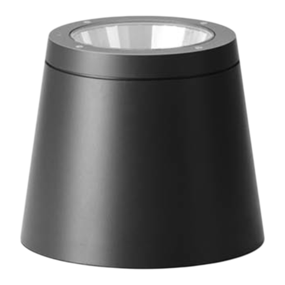
Ground mounted floodlight - adjustable
A
B
C
Figure 1:
Faceplate
Assembly
Optical
Assembly
Luminaire
Housing
Base Plate
Assembly
Mounting
Plate
Figure 2:
11
"
3
4
9"
9
"
3
4
Dimensions
A: 9"
B: 9-3/4"
C: 11-3/4"
3
"
1
2
" (4X)
1
4
FOR MOUNTING
TO WIRING BOX
5
"
1
8
MOUNTING PLATE DETAIL
Maintenance:
Clean regularly with solvent-free cleaner
removing dirt and debris. Do not use high
pressure cleaners.
Replacement Parts
See label inside of fixture for LED replacement
part number.
Consult factory for all other replacement
components.
98 006
REV
CHANGED BY
Updated: 03/29/21
98 006
1 of 2
1000 BEGA Way, Carpinteria, California 93013
APPROVED:
DATE:
Advertisement
Table of Contents

Related Manuals for BEGA 98 006


Summary of Contents for BEGA 98 006
- Page 1 1 of 2 Due to the dynamic nature of lighting products and the associated technologies, luminaire data on this sheet is subject to change at the discretion of BEGA North America. For the most current technical data, please refer to bega-us.com...
- Page 2 2 of 2 Due to the dynamic nature of lighting products and the associated technologies, luminaire data on this sheet is subject to change at the discretion of BEGA North America. For the most current technical data, please refer to bega-us.com...
Need help?
Do you have a question about the 98 006 and is the answer not in the manual?
Questions and answers