Table of Contents
Advertisement
Available languages
Available languages
Quick Links
D j tal kopyası ç n QR kodu okutun.
Scan the QR code for a d g tal copy.
Montaj Talimatı
Installation Instruction
YK 190 MB L
SSH.MT.01.12 - TR - EN
Değişiklik yapma hakkı saklıdır. Türkiye'de basılmıştır. © Yılkar Klima, 2023. The right to make changes is reserved.
Printed in Turkey. © Yılkar Airconditioned, 2023.
YILKAR
TR
EN
Advertisement
Table of Contents

Related Manuals for YILKAR Montaj Talimati YK 190 MB L


Summary of Contents for YILKAR Montaj Talimati YK 190 MB L
- Page 1 YILKAR D j tal kopyası ç n QR kodu okutun. Scan the QR code for a d g tal copy. Montaj Talimatı Installation Instruction YK 190 MB L SSH.MT.01.12 - TR - EN Değişiklik yapma hakkı saklıdır. Türkiye'de basılmıştır. © Yılkar Klima, 2023. The right to make changes is reserved.
- Page 2 04.04.2023 H.Kübra Şahin İlk yayın REVİZYONU YAPAN REVİZYON NO YAYIN TARİHİ REVİZYON NEDENİ KİŞİ REVISION NO PUBLISH DATE REASON FOR REVISION REVISING PERSON SSH.MT.01.12 - TR - EN Değişiklik yapma hakkı saklıdır. Türkiye'de basılmıştır. © Yılkar Klima, 2023. The right to make changes is reserved. Printed in Turkey.
-
Page 3: Table Of Contents
2.3 YK 190 MB L Teknik Veriler..............3.Genel Bakış ......................6 3.1 YK 190 MB L Genel Bakış ............... 6 3.1.1 YILKAR Monoblok Ünitesi .............. 6 3.2 Genel Tanımlama ..................7 4.YK 190 MB L Klima Montajı ................9 4.1 Genel Montaj Şeması ................9 4.2 YK 190 MB L U Bağlantı... - Page 4 5. Klimanın Devreye Alınması ................32 6. Yedek Parça Listesi .................... 33 6.1. Kondanser Yedek Parçalar ..............6.2. Evaporatör Yedek Parçalar ..............6.3. Diğer Yedek Parçalar ................7. Kullanım ve Bakım Önerileri................SSH.MT.01.12 - TR - EN Değişiklik yapma hakkı saklıdır. Türkiye'de basılmıştır. © Yılkar Klima, 2023. The right to make changes is reserved. Printed in Turkey.
- Page 5 2.3 YK 190 MB L Technical Data ..............3.Overview......................43 3.1 YK 190 MB L Overview ................43 3.1.1 YILKAR Monoblock Unit ..............43 3.2 General Description................... 44 4.Installation of Yılkar YK 190 MB L ............... 46 4.1 General Assembly Diagram ..............46 4.2 YK 190 MB L U Connection Profiles Mounting .........
- Page 6 5. Commissioning the Air Conditioner ..............69 6. Spare Parts ......................70 6.1. Condenser Spare Parts ................6.2. Evaporator Spare Parts ................6.3. Other Spare Parts ..................7. Usage and Maintenance Recommendations ............. SSH.MT.01.12 - TR - EN Değişiklik yapma hakkı saklıdır. Türkiye'de basılmıştır. © Yılkar Klima, 2023. The right to make changes is reserved. Printed in Turkey.
-
Page 9: Giriş
1. Giriş Bu talimat YK 190 MB L iklimlendirme cihazının bir parçasıdır. Kurulum için tüm gerekli bilgiler açıklanmakta olup cihazın güvenli kullanımına dair bilgiler içermektedir. Yılkar klima montajını tam olarak yapmanız için lütfen bu montaj talimatını dikkatlice okuyunuz. Güvenli ve temiz yerde muhafaza edilmesi tavsiye edilir. Sorularınız için lütfen servise ve/veya müşteri hizmetlerine başvurunuz. -
Page 10: Garanti Ve Sorumluluk
1.1 Garanti ve Sorumluluk Garanti Şartları YILKAR müşterilerine satın aldıkları ürünlerin günümüz teknolojisine uygun ve hatasız olarak üretildiğinin garantisini vermektedir. Tüm YILKAR Yetkili Satıcıları, aracın hangi yetkili satıcı tarafından satıldığına bakmaksızın, garanti işlemi yapmakla yükümlüdür. Fabrikasyon hatalarda, ürün üzerindeki tüm parçalar teslim tarihinden itibaren 2 (iki) yıl süreyle garanti kapsamındadır. -
Page 11: Güvenlik Ve Yasal Düzenlemeler
Lütfen kendi güvenliğiniz için aşağıda yer alan kurallara dikkat ediniz: Tamir ve bakım işlemleri sadece gerekli eğitim almış ve yetkiye sahip uzman personele yaptırınız. YILKAR yetkili servislerine ait bilgileri , YILKAR’ın resmi web sayfası www.yilkarklima.com ’dan ulaşabilirsiniz. Cihaz çalışır durumda olduğunda elinizi ünitenin içine uzatmayın ve kondanser ile evaporatör fanına herhangi bir yabancı... -
Page 12: Tanım Ve Teknik Bilgiler
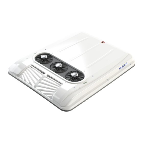
2. Tanım ve Teknik Bilgiler 2.1 YK 190 MB L Nedir? YK 190 MB L 27 koltuğa kadar olan minibüsleri iklimlendirmek için geliştirilen yenilikçi tasarımlı bir tavan üstü iklimlendirme cihazıdır. Kolay montajlanabilir olan ünite, bir kondanser ve bir evaporatör içerir. Bu ünitelerin aracın tavanına montajlanması... -
Page 13: Yk 190 Mb L Teknik Veriler
2.3 YK 190 MB L Teknik Veriler Tablo.1 Teknik Veriler Tavan Tipi Klima Ünitesi YK 190 MB L Soğutucu Kompresörü TM21 - TM31 14 - 19 kW Soğutma Gücü (47000 - 65000 BTU/sa) (12000 - 16300 kcal/sa) Yağ Çeşidi PAG 100 yağ Yağ... -
Page 14: Genel Bakış
1 ADT 310.01.YK190.02 (24V) 500.22.YK190.02 (12V) MONOBLOK GRUBU - YK 190 MB L 1 ADT 500.22.YK190.22 (24V) HAVA EMIS IZGARA KOMPLESI - GRI - YILKAR - 65X22 1 ADT 501.24.HEIPL.09 HORTUM - CELIK TEL - SPIRAL 12 MM 12,5 MT 108.02.HC00M.12... -
Page 15: Genel Tanımlama
3.2 Genel Tanımlama Fiber Kapak Fiber malzemeden üretilen kapak araç tavanında ünite üzerine montaj edilerek üniteyi koruma görevi görür. Kondanser Kondenser klima sisteminde kompresörden aldığı yüksek basınçlı R134a soğutucu gazın çevreye ısı vererek sıvı hale geçtiği klima sistemi elemanıdır. Valf Soğutucu akışkan basıncını... - Page 16 Kompresör Kompresör klima sisteminde R134a klima gazını sıkıştırıp basıncını arttıran sistemin pompasıdır. Röle Kartı Röle klima sisteminde akım ve voltaj değerleri yardımı ile akım yolunu açıp kapatarak anahtarlama yapar. Bu sayede klimanın düzenli çalışmasını sağlar. Klima sistemi için 12V ve 24V opsiyonları bulunmaktadır.
-
Page 17: Yk 190 Mb L Klima Montajı
4. Yılkar YK 190 MB L Montajı 4.1 Genel Montaj Şeması KONDENSER VALF KOMPRESÖR EVAPORATÖR Alçak Basınç Hattı Yüksek Basınç Hattı Yukarıdaki montaj şemasında iklimlendirme cihazı sisteminde hortumlar ile birbirine bağlanan bileşenler üzerinde R134a soğutucu akışkanının akış yönü ve alçak-yüksek basınç... -
Page 18: Yk 190 Mb L U Bağlantı Profilleri Montajı
4.2 YK 190 MB L U Bağlantı Profilleri Montajı Bağlantı sacları kondenser ve evaporatörü araç tavanına ve birbirlerine sabitlemek amacıyla kullanılan öncelikle montajlanması gereken parçalardır. Bu işlemden hemen önce fiber kapağı çıkarınız. Montaj Adım 1: Öncelikle U bağlantı profillerini aracınızın tavanına uygun ölçülerde kesiniz. Montaj Adım 2: Kesilen U profillerinin ray-kulak parçalarını... - Page 19 Montaj Adım 4: Monoblok ünite için kullanılacak U bağlantı profilleri konumu aşağıda gösterilen ölçüde araç içinde tavan üzerinde işaretlenmeli ve matkap uçlu trapez M5x25 vida ile tavana montajı sağlanmalıdır. Bu bağlantı için 24 adet bağlantı vidası kullanılmaktadır. ARAÇ TAVANI EVAPORATÖR BAĞLANTISI İÇİN U ÇİFTLİ...
-
Page 20: Yk 190 Mb L Ünite Montajı
4.3 YK 190 MB L Ünite Montajı 4.3.1 YK 190 MB L Ün te Ölçüler 1960 1600 4.3.2 Ün ten n Konumlandırılması ve Tavan Montajı İklimlendirme cihazını sabitlemek için, aracın tavanına 11 delik açılması gerekmektedir. (4 adet kondenser bağlantı takozları için, 4 adet evaporatör bağlantıları için, 3 adet evaporatör kısmı... - Page 21 Montaj Adım 5: Araç üzerine montajı yapılacak kondenser konumunu montaj kriterlerine uygun olarak aracın üzerinde merkezi hat ile belirleyiniz. Montaj Adım 6: YK 190 MB L için teknik resimde detayları verilen delik açılacak yerleri fiber kapak ölçülerini referans alarak araç üzerinde işaretleyiniz. İşaretlenen yerleri uygun alet ve ekipmanlarla deliniz.
- Page 22 Montaj Adım 7: Araç tavanında monoblok ünitenin altını verilen ölçülere göre 10 mm PE ARMAFLEX ile yalıtınız. 1478 İZOLASYON 1430 MONOBLOK ÜNİTE ALTTAN BAKIŞ *Ölçü birimi milimetredir.
- Page 23 Montaj Adım 8: Araç tavanında titreşim sönümleme amacıyla kullanılan bağlantı takozlarının açılan deliklere montajını yapınız ve SIMSON ISR 70-03 beyaz mastik ile yalıtınız. Montaj Adım 9: Monoblok ünitesini araç tavanına bağlantı takozlarına ve kesilen yerlere denk gelecek şekilde yerleştiriniz. Kondenseri araç tavanına montajlamak için takozlara uygun şekilde M10 somun ile bağlayınız.
- Page 24 Montaj Adım 10: Monoblok ünitenin evaporatör kısmını araç tavanına montajını yapınız. Civatayı gösterilen bağlantı deliklerine tavanın alt tarafından geçirip üst tarafından M10 pul ve M10 somunlarla montajılayınız. Civata Bağlantısı M10 Somun M10 Pul M10X50 Civata...
- Page 25 Montaj Adım 11: Takozlara silikon uyguladıktan sonra evaporatör ünitesinin yerleşeceği alanın etrafına SIMSON ISR 70-03 beyaz mastik uygulayınız. Kondanser ve Evaporatör arası bölgenin sızdırmazlığına dikkat edilmeli ve bu bölgenin sızdırmadığından emin olunmalıdır.
- Page 26 MONOBLOK ÜNİTESİ ÜST GÖRÜNÜŞ...
-
Page 27: Hortum Ve Rekorlar
4.4 Hortum ve Rekorlar İklimlendirme sistemi fabrika tarafından içinde 20 bar basınçla gönderilmektedir. Bağlantı noktalarındaki mevcut tapalar çıkarılırken içinde Azot gazı bulunup bulunmadığı kontrol edilmelidir. İlave evaporatör bağlantısı için 5/8x18 unf inyon kullanılmaktadır. 5/8x18 UNF INYON 13/32 HORTUMU VE 5/8 HORTUMU VE REKOR BAĞLANTISI REKOR BAĞLANTISI Su tahliye hortumu bağlantısı... -
Page 28: Klima Hortum Ve Rekor Bağlantıları
4.4.1 Kl ma Hortum ve Rekor Bağlantıları 4.4.1.1. Kl ma Hortumları Yılkar iklimlendirme sisteminde mevcut bulunan SAE-J 2064 type-E standartlarına uygun hortum çeşitleri, bu hortumlara ait minimum bükülme yarıçapı ve bu hortumlarla kullanılan rekorlar aşağıdaki tabloda mevcuttur. Tablo.2 Klima Hortum Tablosu HORTUM İÇ... -
Page 29: Kelepçe Ve Plastik Adaptörler
PLASTİK ADAPTÖR 5/16"-13,8 13/32''-17 5/8"-25,6 5/8"-25,6 4.4.1.4. Hortum ve Rekor Montajı 1-Öncelikle hortumları düz bir şekilde kesiniz. (1) 2-Rekorun geçeceği hortumun iç kısmını yağlayınız. 3-Rekorları hortumlara düzgün bir şekilde oturtunuz. (2)(3) 4-Pense yardımıyla kelepçeleri sıkınız. (4)(5) HORTUM YILKAR KOD: 212.01.P0000.05... - Page 30 13/32 , 5/8 ve 5/16 hortumlarını iç ve dış etkenlerden koruyacak şekilde montajlayınız. Aracın hareketli elemanlarından ve sıcak bölgelerinden uzak tutunuz, hattın geçeceği tüm keskin kenar ve köşelerden izole ederek montajı yapınız. Hortumları minimum bükülme yarıçapına uygun şekilde bükünüz. Tüm bağlantıları yapıldıktan sonra hortumları kablo bağları ile araca sabitleyiniz.
-
Page 31: Elektrik Bağlantıları
4.5 Elektrik Bağlantıları 4.5.1 Kontrol Ün tes Montajı Montaj yapılacak yüzey YLK 12/24 Kontrol Ünitesi Ünite konumu ergonomik olarak sürücünün erişilebileceği bir alanda düz bir yüzey olarak seçilmelidir. Montaj yüzeyi ölçüleri 90x45 mm olmalıdır. Kontrol paneli soketlerini şekilde gösterildiği gibi üniteye montajlayınız. Montajladıktan sonra kilitleri kontrol ediniz. - Page 32 Klimayı korumak için, ilave kofra seti kullanılmaktadır. Sigorta kutusu kolay ulaşılabilecek bir bölgeye montajlanmalıdır. 80A sigortayı, sigorta kutusundaki civataların olduğu bölgeye yerleştiriniz. Montaj kitindeki 16 mm B+ kablosunun M6 kablo ucunu sigortanın bir tarafına geçiriniz. Diğer M8 kablo ucunu aracın aküsünün (+) kutbuna yerleştiriniz. 16 mm B+ kablosunun M6 kablo ucunu sigortanın bir tarafına geçiriniz.
-
Page 33: Kablo Bağlantısı Ve Devre Şeması
4.5.2 Kablo Bağlantısı ve Devre Şeması Dış Sıcaklık Sensörü İç Sıcaklık Sensörü KOMPRESÖR ŞARJ DİNAMOSU KOFRA 80A (-) Şase (-) Şase DÖRT YOL MÜŞÜR BLOWER BLOWER MOTOR MOTOR EMİŞ MÜŞÜRÜ BLOWER BLOWER MOTOR MOTOR KONDENSER MOTOR KONDENSER MOTOR KONDENSER MOTOR Şase... - Page 34 Açıklama Kablo Çap ve Renkleri 1. Fan Blower 1. Hız Turuncu 1.50 mm² 2. Fan Blower 2. Hız Gri 1.50 mm² 3. Fan Blower 3. Hız Beyaz 1.50 mm² 4. Kondanser Motor Mavi 1.50 mm² 5. Fan Kontrollü Motor Kırmızı 1.50 mm² 6.
-
Page 35: Kontrol Ünitesi Genel Bakış
4.5.3 Kontrol Ün tes Genel Bakış Dijital kumanda, ünitedeki sıcaklık propları yardımıyla otomatik olarak ayarlanmış set değerleri sayesinde klimayı devreye alıp çıkartmaya yardımcı olur 32° 18° 21° Set sıcaklığı arttır Isıtma aç / kapat (Opsiyonel) Set sıcaklığı azalt Klape aç / kapat (Opsiyonel) Fan hızı... -
Page 36: Kontrol Ünitesi Çalıştırma
4.5.4 Kontrol Ün tes Çalıştırma 4.5.4.1 Soğutma Soğutma modunu başlatmak için, 32° soğutma butonuna basın. 18° Ekranda işareti çıktığında klimanız 21° soğutma modunda çalışır. 4.5.4.2 Isıtma (Ops yonel) Isıtma modunu başlatmak için, ısıtma 18° butonuna basın. 32° Ekranda işareti çıktığında klimanız 21°... - Page 37 Tablo.5 Teknik Bilgi Tablosu Besleme Voltajı 12 V - 24 V Ort. Elektriksel Tüketim 400 mA @12V @25°C Çalışma Sıcaklığı -10° C --- +45° C Hata Kodları Hata kodu 21° E 1 : İç Sıcaklık Sensörü Açık Devre Oluşma Nedeni: Kablo kesilmiş veya soket çıkmış olabilir. Sensör arızalanmış veya kırılmış...
-
Page 38: Fiber Kapak Montajı
4.6 F ber Kapak Montajı 1960 1600 Tüm montajlar tamamlandıktan sonra klimayı devreye almadan önce fiber kapağı takınız. Klimanıza ait fiber kapağı takmadan önce kapağın lastiklerinin tam olarak geçtiğinden emin olunuz, ardından kondenserin üzerine tam oturacak şekilde araç tavanına paralel yerleştiriniz. - Page 39 MONOBLOK ÜNİTESİ SON GÖRÜNÜŞ...
- Page 40 5. Klimanın Devreye Alınması Azot İle Sistemin Kaçak Kontrolü; Sisteme Azot gazı verildikten sonra sabunlu su ile kaçak kontrolü yapılır. Bu aşamada bakılması gereken noktalar rekor bağlantılarıdır. Bağlantı noktalarında hava kabarcığı olup olmadığı gözlemlenmelidir. 2. Sistemin Vakum Pompası İle Vakumlanması; Kompresör tarafından bağlanan vakum pompası...
- Page 41 6. Yedek Parçalar 6.1 Kondenser Yedek Parçalar 502.01.01301.02 (12V) KONDENSER MOTOR GRUBU - 1301 - HP KANAT X3 ADT 502.01.01301.22 (24V) KONDANSER BATARYA - ALM BORU PARALEL-1143X552X25,4 X1 ADT 104.02.11012.02 BORU - 1301 5/8X18 U CIKIS DEPO GIRIS QUICK X1 ADT 101.12.01301.04 BORU - 1506 KONDANSER EVAP ARA ADAPTOR (19 KW) X1 ADT 101.12.01506.02...
- Page 42 6.2 Evaporatör Yedek Parçalar EVAPORATOR BATARYA - ALM BORU+EXP VALF - 1506 X2 ADT 104.01.11011.01 503.94.RLK03.01 (12V) ROLE KARTI URT - YLK628 - MB X1 ADT 503.94.RLK03.02 (24V) 105.10.BL12N.B1 (12V) FAN - BLOWER - BASKURT 700 X4 ADT 105.10.BL24N.B1 (24V) VALF - EXP - SANHUA RFGD04E-6.8-850 X1 ADT 104.04.4SN01.03 KILCAL DENGELEME X1 ADT...
- Page 43 6.3 Diğer Yedek Parçalar FIBER - KAPAK - YK 190 MB L SACLI GEÇME FİTİL (5 m) 321.02.YK190.02 103.02.FT001.01 32° 18° 21° DİJİTAL KLİMA KONTROL PANELİ x1 ADT KOFRA x1 ADT 105.01.KU010.01 503.92.KFSET.01 KOMPRESÖR - VALEO TM21 KOMPRESÖR - VALEO TM31 x1 ADT x1 ADT 504.03...
- Page 44 ünitenin kullanıldığı araca göre ölçü, adet ve çeşitlilik açısından farklılık gösterebilmektedir. Tamir işlemleri esnasında her zaman orijinal yedek parça kullanılmalıdır. YILKAR tarafından onaylanmamış olan parçalar, ünitenin güvenliğini ve düzgün çalışmasını olumsuz etkileyebilir. Bu tür durumlarda ünite GARANTİ kapsamından çıkar.
- Page 45 7. Kullanım Ve Bakım Önerileri İklimlendirme cihazının işleyişini iyileştirmek için sistemin rutin bakımını yapınız. Bakım ve temizleme işlemleri için iklimlendirme cihazının kapağını açmadan önce, aracın akü bağlantısını kesiniz. Sistemi temizlerken elektrikli bileşenleri koruyunuz. Her mevsim başlangıcında, elektrikli bileşenler dâhil sistemin tüm bileşenlerini muayene ediniz. Yılda iki kere, kompresör izleyen kayışının gerginliğini kontrol ediniz;...
- Page 47 1. Introduction This instruction is part of the YK 190 MB L air conditioner. All necessary information for installation is explained and includes information on safe use of the device. Please read this installation instruction carefully in order to fully install Yılkar air conditioner. It is recommended to be stored in a safe and clean place.
- Page 48 1.1 Warranty and Liability Warranty conditions YILKAR assures its customers that the products they buy are manufactured in accordance with today's technology and without any errors. All YILKAR Authorized Dealers are obliged to carry out warranty transactions regardless of which authorized dealer the vehicle is sold by.
- Page 49 Have repair and maintenance operations performed only by qualified personnel who have received the necessary training and authorization. You can find information about YILKAR authorized service centers on YILKAR's official website, www.yilkarklima.com. Do not reach into the unit and do not hold any foreign objects to the condenser and evaporator fan when the device is in operation.
- Page 50 2. Definition and Technical Information 2.1 What is YK 190 MB L? YK 190 MB L is an innovative designed air conditioning device developed for air conditioning minibuses up to 27 seats. The easy-to-install unit includes a condenser and an evaporator. These units must be mounted on the roof of the vehicle and connected to the compressor via hoses circulating R134a refrigerant.
- Page 51 2.3 YK 190 MB L Technical Data Table.1 Technical Data Roof Type Air Conditioning Unit YK 190 MB L Compressor TM21 - TM31 14 - 19 kW Cooling Power (47000 - 65000 BTU/h) (12000 - 16300 kcal/h) Oil Type PAG 100 oil Oil Amount 250 ccm Refrigerant / Amount...
- Page 52 1 PCS 310.01.YK190.02 (24V) 500.22.YK190.02 (12V) MONOBLOCK GROUP - YK 190 MB L 1 PCS 500.22.YK190.22 (24V) AIR SUCTION GRILL COMPLETEGRAY - YILKAR - 65X22 1 PCS 501.24.HEIPL.09 HOSE - STEEL WIRE - SPIRAL 12 MM 12,5 MT 108.02.HC00M.12 AIR CONDITIONING - WEDGE CONNECTION COMPLETE - 20 MM 1 SET 504.01.YKMON.01...
- Page 53 3.2 General Description Fiber Cover The cover made of fiber material is mounted on the condenser unit on the vehicle roof and acts as a condenser protection. Condenser It is the air conditioning system element in which the high pressure R134a refrigerant gas taken from the compressor in the condenser air conditioning system becomes liquid by giving heat to the environment.
- Page 54 Compressor It is the pump of the system that compresses the R134a air conditioner gas in the compressor air conditioning system and increases its pressure. Relay Board The relay switches on and off the current path with the help of current and voltage values in the air conditioning system.
- Page 55 4. Installation of Yılkar YK 190 MB L 4.1 General Assembly Diagram CONDENSER VALVE COMPRESSOR EVAPORATOR Low Pressure L ne H gh Pressure L ne In the above assembly diagram, the flow direction of the R134a refrigerant and the low- high pressure zones are shown on the components connected to each other by hoses in the air conditioner system.
- Page 56 4.2 YK 190 MB L U Connection Profiles Mounting Connection plates are the first mounting parts used to fix the condenser and evaporator to the vehicle roof and to each other. Remove the fiber cover just before this procedure. Assembly Step 1: First of all, cut the U-connection profiles to the dimensions suitable for the roof of your vehicle.
- Page 57 Assembly Step 4: The position of the U connection profiles to be used for the monoblock unit should be marked on the roof in the vehicle as shown below, and it should be mounted to the roof with a drill-tipped trapezoidal M5x25 screw. 24 connection screws are used for this connection.
- Page 58 4.3 Monoblock Unit Mounting 4.3.1 YK 190 MB L Un t D mens ons 1960 1600 4.3.2 Un t Pos t on ng and Roof Mount ng To fix the air conditioner, 11 holes must be drilled in the roof of the vehicle. (4 for condenser connection wedges, 4 for evaporator connections, 3 for evaporator part opening.
- Page 59 Assembly Step 5: Determine the location of the condenser to be mounted on the vehicle with the central line on the vehicle in accordance with the mounting criteria. Assembly Step 6: For YK 190 MB L, mark the places to be drilled, the details of which are given in the technical drawing, on the vehicle by referring to the fiber cover dimensions.
- Page 60 Assembly Step 7: Insulate the bottom of the monoblock unit on the roof of the vehicle with 10 mm PE ARMAFLEX according to the given dimensions. 1478 INSULATION 1430 MONOBLOCK UNIT BOTTOM VIEW *Dimentions type is milimeter.
- Page 61 Assembly Step 8: Mount the mounting wedges used for vibration damping on the vehicle roof to the drilled holes and insulate with SIMSON ISR 70-03 white mastic. Assembly Step 9: Place the monoblock unit on the vehicle roof so that it coincides with the mounting wedges and the cut places.
- Page 62 Assembly Step 10: Mount the evaporator part of the monoblock unit to the vehicle roof. Insert the bolts from the bottom of the roof into the indicated connection holes and mount them with M10 washers and nuts from the top. Bolt Connection M10 Nut M10 Washer...
- Page 63 Assembly Step 11: After applying silicone to the wedges, apply SIMSON ISR 70-03 white sealant around the area where the evaporator unit will be placed. Attention should be paid to the sealing of the area between the condenser and the evaporator and it should be ensured that this area does not leak.
- Page 64 MONOBLOCK UNIT TOP VIEW...
- Page 65 4.4 Hoses and Fitting The air conditioning system is sent by the factory with a pressure of 20 bar inside. While removing the existing plugs at the connection points, it should be checked whether there is Nitrogen gas in it. 5/8x18 unf inion is used for additional evaporator connection.
- Page 66 4.4.1 A r Cond t oner Hose and F tt ng Connect ons 4.4.1.1. A r Cond t oner Hose The hose types in compliance with SAE-J 2064 type-E standards available in Yılkar air conditioning system, the minimum bending radius of these hoses and the unions used with these hoses are given in the table below.
- Page 67 1-First of all, cut the hoses straight. (1) 2-Lubricate the inner part of the hose where the union will pass. 3-Put the unions on the hoses properly. (2)(3) 4-Tighten the clamps with the help of pliers. (4)(5) HOSE YILKAR CODE: 212.01.P0000.05...
- Page 68 Assemble 13/32 , 5/8 and 5/16 hoses to protect them from internal and external factors. Keep away from the moving elements and hot parts of the vehicle, make the assembly by isolating it from all sharp edges and corners where the line will pass.
- Page 69 4.5 Electrical Connections 4.5.1 Control Un t Mount ng Surface to be mounted YLK 12/24 Control unit The unit location should be ergonomically chosen as a flat surface in an area accessible to the driver. Mounting surface dimensions should be 90x45 mm. Assemble the control panel sockets to the unit as shown in the figure.
- Page 70 Place the 80A fuse in the area of the bolts in the fuse box. Pass the M6 wire end of the 16 mm B+ cable in the mounting kit to one side of the fuse. Place the other M8 cable end on the (+) terminal of the vehicle's battery. Pass the M6 wire end of the 16 mm B+ wire to one side of the fuse.
- Page 71 4.5.2 W r ng and C rcu t D agram Outdoor Temperature Sensor Internal Temperature Sensor COMPRESSOR GENERATOR TERMINAL BOX 80A (-) Frame GND (-) Frame GND FOUR-WAY SWITCH BLOWER BLOWER ENGINE ENGINE LOW PRESSURE SWITCH BLOWER BLOWER ENGINE ENGINE CONDENSER ENGINE CONDENSER ENGINE CONDENSER ENGINE...
- Page 72 Description Cable Diameter and Colors 1. Fan Blower 1. Speed Orange 1.50 mm² 2. Fan Blower 2. Speed Grey 1.50 mm² 3. Fan Blower 3. Speed White 1.50 mm² 4. Condenser Engine Blue 1.50 mm² 5. Fan Controlled Motor Red 1.50 mm² 6.
- Page 73 4.5.3 Control Un t Owerv ew The digital controller helps to activate and deactivate the air conditioner by automatically adjusted set values with the help of temperature probes in the unit. 32° 18° 21° Increase set temperature Heating on / off (Optional) Decrease set temperature Flap open / close (Optional) Changing the fan speed...
- Page 74 4.5.4 Control Un t Operat ng 4.5.4.1 Cool ng To start the cooling mode, press the cooling button. When the snowflake sign appears on 32° 18° the screen, your air conditioner operates 21° in cooling mode. 4.5.4.2 Heat ng (Opt onal) To start the heating mode, press the 18°...
- Page 75 Table.5 Technical Information Table Supply Voltage 12 V - 24 V Average Electrical Consumption 400 mA @12V @25C Operating Temperature - 10 C --- + 40 C Fault Codes Fault code 21° E 1 : Inside Temperature Sensor Open Circuit Cause of Occurrence: The cable may have been cut or the socket may have come off.
- Page 76 4.6 F ber Cover Assembly 1960 1600 After all installations are completed, install the fiber cover before commissioning the air conditioner. Before installing the fiber cover of the air conditioner, make sure that the rubbers of the cover are fully inserted, then place it parallel to the vehicle roof so that it fits over the condenser.
- Page 77 MONOBLOCK UNIT FINAL VIEW...
- Page 78 5. Commissioning the Air Conditioner Leakage Control of the System with Nitrogen; After giving Nitrogen gas to the system, leakage control is done with soapy water. The points to look at at this stage are the record connections. It should be observed whether there are air bubbles at the connection points.
-
Page 79: Spare Parts
6. Spare Parts 6.1 Condenser Spare Parts 502.01.01301.02 (12V) CONDENSER MOTOR GROUP - 1301 - HP IMPELLER X3 PCS 502.01.01301.22 (24V) CONDENSER BATTERY - ALM PIPE PARALLEL - 1143X552X25,4 X1 PCS 104.02.11012.02 PIPE - 1301 5/8X18 U OUTLET TANK INLET QUICK X1 PCS 101.12.01301.04 PIPE - 1506 CONDENSER EVAP INTERMEDIATE ADAPTOR (19 KW) x1 PCS 101.12.01506.02... -
Page 80: Evaporator Spare Parts
6.2 Evaporator Spare Parts EVAPORATOR BATTERY - ALM PIPE+EXP VALVE - 1307 X2 PCS 104.01.11011.01 503.94.RLK03.01 (12V) RELAY BOARD ASSEMBLY - YLK 628 X1 PCS 503.94.RLK03.02 (24V) 105.10.BL12N.B1 (12V) FAN - BLOWER - BASKURT 700 X4 PCS 105.10.BL24N.B1 (24V) VALVE - EXP - SANHUA RFGD04E -6.8-850 X1 PCS 104.04.4SN01.03 BALANCING X1 PCS 104.10.KD001.01... -
Page 81: Other Spare Parts
6.3 Other Spare Parts FIBER - COVER - YK 190 MB L x1 PCS WICK - LUGGAGE RUBBER (5 m) 321.02.YK190.02 103.02.FT001.01 32° 18° 21° DIGITAL AIR CONDITIONER CONTROL PANEL TERMINAL BOX x1 PCS x1 PCS 503.92.KFSET.01 105.01.KU010.01 COMPRESSOR - VALEO TM21 COMPRESSOR - VALEO TM31 x1 ADT x1 ADT... - Page 82 Original spare parts should always be used during repairs. Parts not approved by YILKAR may adversely affect the safety and proper operation of the unit. In such cases, the unit is out of WARRANTY. For a fast and accurate shipment of spare parts, we kindly ask you to provide the following information: 1.
-
Page 83: Usage And Maintenance Recommendations
7. Usage and Maintenance Recommendations Perform routine maintenance of the system to improve the operation of the air conditioner. Before opening the cover of the air conditioner for maintenance and cleaning operations, disconnect the vehicle's battery. Protect electrical components while cleaning the system. At the beginning of each season, inspect all components of the system, including electrical components. - Page 84 Vehicle Heating Cooling and Ventilation Systems Phone : +90 224 215 53 28 (pbx) : +90 224 215 99 24 Address : Küçükbalıklı Mah. 580.Sok No:6 Osmangazi / BURSA / TURKEY www.yilkarklima.com...
Need help?
Do you have a question about the Montaj Talimati YK 190 MB L and is the answer not in the manual?
Questions and answers