
Related Manuals for YILKAR YK 120 S


Summary of Contents for YILKAR YK 120 S
- Page 1 YILKAR Installation Instruction YK 120 S SSH.MT.01.02 - EN The right to make changes is reserved. Printed in Turkey. © Yılkar Airconditioned, 2023...
- Page 2 27.12.2022 H.Kübra Şahin First Publication REVISION NO PUBLISH DATE REVISING PERSON REASON FOR REVISION SSH.MT.01.02 - EN The right to make changes is reserved. Printed in Turkey. © Yılkar Airconditioned, 2023...
-
Page 3: Table Of Contents
3.2 General Description................... 4.Installation of Yılkar YK 120 S ................4.1 General Assembly Diagram ..............4.2 YK 120 S U Connection Profiles Mounting ..........4.3 YK 120 S Outdoor Unit Installation ............4.3.1 Outdoor Unit Dimensions .............. 4.3.2 Outdoor Unit Positioning and Roof Mounting ........ - Page 4 4.6.4 Control Unit Operation ..............4.6.4.1 Cooling ................4.6.4.2 Heating (Optional) ............... 4.6.4.3 Ventilating ................4.7 Fiber Cover Mounting ................5. Commissioning the Air Conditioner ..............6. Spare Parts ......................6.1. Condenser Spare Parts ................6.2. Evaporator Spare Parts ................6.3.
-
Page 5: Introduction
1. Introduction This instruction is part of the YK 90 S air conditioner. All necessary information for installation is explained and includes information on safe use of the device. Please read this installation instruction carefully in order to fully install Yılkar air conditioner. It is recommended to be stored in a safe and clean place. -
Page 6: Warranty And Liability
1.1 Warranty and Liability Warranty conditions YILKAR assures its customers that the products they buy are manufactured in accordance with today's technology and without any errors. All YILKAR Authorized Dealers are obliged to carry out warranty transactions regardless of which authorized dealer the vehicle is sold by. -
Page 7: Security And Legal Regulations
Have repair and maintenance operations performed only by qualified personnel who have received the necessary training and authorization. You can find information about YILKAR authorized service centers on YILKAR's official website, www.yilkarklima.com. Do not reach into the unit and do not hold any foreign objects to the condenser and evaporator fan when the device is in operation. -
Page 8: Definition And Technical Information
2. Definition and Technical Information 2.1 What is YK 120 S ? YK 120 S is an innovative designed air conditioning device developed for air conditioning minibuses up to 17 seats. The easy-to-install unit includes a condenser and an evaporator. These units must be mounted on the roof of the vehicle and connected to the compressor via hoses circulating R134a refrigerant. -
Page 9: Yk 120 S Technical Data
2.3 YK 120 S Technical Data Table.1 Technical Data Roof Type Air Conditioning Unit YK 120 S Compressor SD5-SD7-TM16 9 - 12 kW Cooling Power (30709 - 40945 BTU/sa) (7738 - 10318 kcal/sa)) Oil Type PAG 100 oil Oil Amount... -
Page 10: Overview
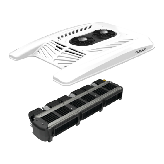
3. Overview 3.1 YK 120 S Overview 3.1.1. YILKAR Condenser Un t 312.02.01301.01 (12V) CONDENSER UNIT- 1301 1 Piece 312.02.01301.21 (24V) 502.11.01301.01 (12V) CONDENSER GROUP - 1301 1 Piece 502.11.01301.21 (24V) AIR CONDITIONING - HOSE CONNECTION 1 Piece 504.01.YKMON.33 GROMET... -
Page 11: Yilkar Evaporator Unit
3.1.2. YILKAR Evaporator Un t 311.02.YK120.01 (12V) EVAPARATOR UNIT - YK 120 S 1 Piece 311.02.YK120.21 (24V) 501.21.YK120.01 (12V) EVAPARATOR GROUP - YK 120 S - 2007 1 Piece 501.21.YK120.21 (24V) U - DOUBLE - RAIL-EAR 70 CM COMPLETE 1 SET 502.51.UC005.01... -
Page 12: Yilkar Fiber Cover
3.1.3. YILKAR F ber Cover FIBER - COVER - 1301 - MEDIUM 1 ADT 321.01.01301.02 FIBER - RAW - COVER - 1301 - MEDIUM 1 ADT 504.11.01301.02 WICK - LUGGAGE RUBBER 1ADT 103.02.FT001.01... -
Page 13: General Description
3.2 General Description Fiber Cover The cover made of fiber material is mounted on the condenser unit on the vehicle roof and acts as a condenser protection. Condenser It is the air conditioning system element in which the high pressure R134a refrigerant gas taken from the compressor in the condenser air conditioning system becomes liquid by giving heat to the environment. - Page 14 Compressor It is the pump of the system that compresses the R134a air conditioner gas in the compressor air conditioning system and increases its pressure. Relay Board The relay switches on and off the current path with the help of current and voltage values in the air conditioning system.
-
Page 15: Installation Of Yılkar Yk 120 S
4. Yılkar YK 120 S Installation 4.1 General Assembly Diagram CONDENSER VALVE COMPRESSOR EVAPORATOR Low Pressure L ne H gh Pressure L ne In the above assembly diagram, the flow direction of the R134a refrigerant and the low- high pressure zones are shown on the components connected to each other by hoses in... -
Page 16: Yk 120 S U Connection Profiles Mounting
4.2 YK 120 S U Connection Profiles Mounting Connection plates are the first mounting parts used to fix the condenser and evaporator to the vehicle roof and to each other. Remove the fiber cover and evaporator plastic covers just before this procedure. - Page 17 Assembly Step 4: The position of the U connection profiles to be used for the condenser and evaporator should be marked on the ceiling in the vehicle as shown below and mounted to the ceiling with a drill-tipped trapezoidal M5x25 screw. 16 connection screws are used for this connection.
-
Page 18: Yk 120 S Outdoor Unit Installation
4.3 YK 120 S Outdoor Unit Installation 4.3.1 YK 120 S Outdoor Un t D mens ons 4.3.2 Outdoor Un t Pos t on ng and Roof Mount ng To fix the air conditioner, it is necessary to drill 5 holes in the roof of the vehicle. - Page 19 Assembly Step 6: For YK 120 S, mark the places to be drilled, the details of which are given in the technical drawing, on the vehicle by referring to the fiber cover dimensions. Drill the marked places with suitable tools and equipment.
- Page 20 Assembly Step 7: Mount the mounting wedges used for vibration damping on the vehicle roof to the drilled holes and insulate with SIMSON ISR 70-03 white mastic. Assembly Step 8: Assemble the hose grommet to the hole drilled for the grommet on the vehicle roof and insulate it with SIMSON ISR 70-03 white mastic.
- Page 21 OUTDOOR UNIT TOP VIEW...
-
Page 22: Yk 120 S Indoor Unit Installation
4.4 YK 120 S Indoor Unit Installation 4.4.1 YK 120 S Indoor Un t D mens on 1300 Hava Akış Yönü 4.4.2 Indoor Un t Pos t on ng and Roof Mount ng Assembly Step 10: Assemble the evaporator unit to the U-profiles previously mounted on the vehicle with drill- tipped trapezoidal hexagon head M 5x25 screws. - Page 23 There should be minimum 10 cm space behind the blower motor of in the unit installed at the desired location. DRIVE DIRECTION 10 cm...
- Page 24 INDOOR UNIT VIEW...
-
Page 25: Hoses And Fitting
4.5 Hoses and Fitting The air conditioning system is sent by the factory with a pressure of 20 bar inside. While removing the existing plugs at the connection points, it should be checked whether there is Nitrogen gas in it. - Page 26 13/32 HOSE AND FITTING CONNECTION 5/16 HOSE AND 5/16 HOSE AND FITTING FITTING CONNECTION CONNECTION 5/8 HOSE AND FITTING Ø12 WATER HOSE CONNECTION For the water discharge hose connection, the clamps located behind the stage in the evaporator Stage water discharge section should be tightened as shown in the figure.
-
Page 27: Air Conditioner Hoses And Fitting Connections
4.5.1 A r Cond t oner Hose and F tt ng Connect ons The hose types in compliance with SAE-J 2064 type-E standards available in Yılkar air conditioning system, the minimum bending radius of these hoses and the unions used with these hoses are given in the table below. -
Page 28: Clamp And Plastic Adapters
1-First of all, cut the hoses straight. (one) 2-Lubricate the inner part of the hose where the union will pass. 3-Put the unions on the hoses properly. (2)(3) 4-Tighten the clamps with the help of pliers. (4)(5) HOSE YILKAR CODE: 212.01.P0000.05... - Page 29 Assemble 13/32 , 5/8 and 5/16 hoses to protect them from internal and external factors. Keep away from the moving elements and hot parts of the vehicle, make the assembly by isolating it from all sharp edges and corners where the line will pass.
-
Page 30: Electrical Connections
4.6 Electrical Connections 4.6.1 Control Un t Mount ng Surface to be mounted YLK 12/24 Control unit The unit location should be ergonomically chosen as a flat surface in an area accessible to the driver. Mounting surface dimensions should be 90x45 mm. Assemble the control panel sockets to the unit as shown in the figure. - Page 31 To protect the air conditioner, an additional terminal box set is used. The fuse box should be installed in an easily accessible area. Place the 80A fuse in the area of the bolts in the fuse box. Pass the M6 wire end of the 16 mm B+ cable in the mounting kit to one side of the fuse.
-
Page 32: Wiring And Circuit Diagram
4.6.2 W r ng and C rcu t D agram... - Page 33 Description Cable Diameter and Colors 1. Fan Blower 1. Speed Orange 1.50 mm² 2. Fan Blower 2. Speed Grey 1.50 mm² 3. Fan Blower 3. Speed White 1.50 mm² 4. Condanser Engine Blue 1.50 mm² 5. Fan Controlled Motor Red 1.50 mm² 6.
-
Page 34: Control Unit Owerview
4.6.3 Control Un t Owerv ew The digital controller helps to activate and deactivate the air conditioner by automatically adjusted set values with the help of temperature probes in the unit. 32° 18° 21° Increase set temperature Heating on / off (Optional) Decrease set temperature Flap open / close (Optional) Changing the fan speed... -
Page 35: Control Unit Operation
4.5.4 Control Un t Operat ng 4.5.4.1 Cool ng To start the cooling mode, press the cooling button. When the snowflake sign appears on 32° 18° the screen, your air conditioner operates 21° in cooling mode. 4.5.4.2 Heat ng (Opt onal) To start the heating mode, press the 18°... - Page 36 Table.5 Technical Information Table Supply Voltage 12 V - 24 V Average Electrical Consumption 400 mA @12V @25C Operating Temperature - 10 C --- + 40 C Fault Codes Fault code 21° E 1 : Inside Temperature Sensor Open Circuit Cause of Occurrence: The cable may have been cut or the socket may have come off.
-
Page 37: Fiber Cover Mounting
4.7 F ber Cover Mount ng 1680 1200 After all installations are completed, install the evaporator plastic covers and fiber cover before commissioning the air conditioner. Before installing the fiber cover of the air conditioner, make sure that the rubbers of the cover are fully inserted, then place it parallel to the vehicle roof so that it fits over the condenser. -
Page 38: Commissioning The Air Conditioner
5. Commissioning the Air Conditioner Leakage Control of the System with Nitrogen; After giving Nitrogen gas to the system, leakage control is done with soapy water. The points to look at at this stage are the record connections. It should be observed whether there are air bubbles at the connection points. -
Page 39: Spare Parts
6. Spare Parts 6.1 Condenser Spare Parts 502.11.01301.01 (12V) CONDENSER MOTOR GROUP - 1301 - S IMPELLER x2 PIECES 502.01.01301.21 (24V) CONDANSER BATTERY- ALM PIPE PARALLEL - 750X552X20 x1 PIECE 104.02.11005.02 COMPACT FILTER - Ø89 - ALM X1 PIECE 104.09.CD002.89 PIPE - 1301 5/8X18 U OUTLET TANK INLET QUICK X1 PIECE 101.12.01301.04 SENSOR - COMPLETE - 2/15/25 BAR 4 Way X1 PIECE... -
Page 40: Evaporator Spare Parts
6.2 Evaporator Spare Parts ALM EVAPORATOR BATTERY x1 PIECE 104.01.11013.01 331.04.RLK01.01 (12V) RELAY BOARD ASSEMBLY - YLK610 - 2015 / 2016 x1 PIECE 331.04.RLK01.02(24V) 105.10.BL12N.B1 (12V) FAN - BLOWER - BASKURT 700 X3 PIECES 105.10.BL24N.B1 (24V) AIR SUCTION GRILL PLASTIC - 4 - BLACK x1 PIECE 501.24.HEIPL.11 VALVE - BLOCK - XINJING - 2220-01 x1 PIECE 104.04.4SN00.01... -
Page 41: Other Spare Parts
6.3 Other Spare Parts FIBER - COVER - 1301 - MEDIUM x1 PIECE SACLI GEÇME FİTİL (5 m) 321.01.01301.02 103.02.FT001.01 32° 18° 21° DIGITAL AIR CONDITIONER CONTROL PANEL TERMINAL BOX x1 PIECE x1 PIECE 503.92.KFSET.01 105.01.KU010.01 COMPRESSOR - SANDEN SD5S14 COMPRESSOR - SANDEN SD7H15 x1 PIECE x1 PIECE... - Page 42 ünitenin kullanıldığı araca göre ölçü, adet ve çeşitlilik açısından farklılık gösterebilmektedir. Tamir işlemleri esnasında her zaman orijinal yedek parça kullanılmalıdır. YILKAR tarafından onaylanmamış olan parçalar, ünitenin güvenliğini ve düzgün çalışmasını olumsuz etkileyebilir. Bu tür durumlarda ünite GARANTİ kapsamından çıkar.
-
Page 43: Usage And Maintenance Recommendations
7. Usage and Maintenance Recommendations Perform routine maintenance of the system to improve the operation of the air conditioner. Before opening the cover of the air conditioner for maintenance and cleaning operations, disconnect the vehicle's battery. Protect electrical components while cleaning the system. At the beginning of each season, inspect all components of the system, including electrical components. - Page 44 Vehicle Heating Cooling and Ventilation Systems Phone : +90 224 215 53 28 (pbx) : +90 224 215 99 24 Address : Küçükbalıklı Mah. 580.Sok No:6 Osmangazi / BURSA / TURKEY www.yilkarklima.com...
Need help?
Do you have a question about the YK 120 S and is the answer not in the manual?
Questions and answers