Table of Contents
Advertisement
Quick Links
Advertisement
Table of Contents
Troubleshooting

Related Manuals for Miller SUBARC WIRE DRIVE 400 T CE


Summary of Contents for Miller SUBARC WIRE DRIVE 400 T CE
- Page 1 OM-253789G 2017−01 Processes Submerged Arc (SAW) Welding Description Heavy Duty Wire Feeder For Automated Welding Applications SUBARC WIRE DRIVE 400 T Motor/Drive Assembly For product information, Owner’s Manual translations, and more, visit www.MillerWelds.com...
- Page 2 We know you don’t have time to do it any other way. That’s why when Niels Miller first started building arc welders in 1929, he made sure his products offered long-lasting value and superior quality.
-
Page 3: Table Of Contents
TABLE OF CONTENTS SECTION 1 − SAFETY PRECAUTIONS - READ BEFORE USING ....... . . 1-1. - Page 4 DECLARATION OF CONFORMITY for European Community (CE marked) products. MILLER Electric Mfg. Co., 1635 Spencer Street, Appleton, WI 54914 U.S.A. declares that the product(s) identified in this declaration conform to the essential requirements and provisions of the stated Council Directive(s) and Standard(s).
-
Page 5: Section 1 − Safety Precautions - Read Before Using
SECTION 1 − SAFETY PRECAUTIONS - READ BEFORE USING som 2015−09 Protect yourself and others from injury — read, follow, and save these important safety precautions and operating instructions. 1-1. Symbol Usage DANGER! − Indicates a hazardous situation which, if Indicates special instructions. - Page 6 D Remove stick electrode from holder or cut off welding wire at FUMES AND GASES can be hazardous. contact tip when not in use. D Wear body protection made from durable, flame−resistant material Welding produces fumes and gases. Breathing (leather, heavy cotton, wool). Body protection includes oil-free these fumes and gases can be hazardous to your clothing such as leather gloves, heavy shirt, cuffless trousers, high health.
-
Page 7: Additional Symbols For Installation, Operation, And Maintenance
1-3. Additional Symbols For Installation, Operation, And Maintenance FIRE OR EXPLOSION hazard. MOVING PARTS can injure. D Do not install or place unit on, over, or near D Keep away from moving parts such as fans. combustible surfaces. D Keep all doors, panels, covers, and guards D Do not install unit near flammables. -
Page 8: California Proposition 65 Warnings
1-4. California Proposition 65 Warnings Welding or cutting equipment produces fumes or gases This product contains chemicals, including lead, known to which contain chemicals known to the State of California to the state of California to cause cancer, birth defects, or other cause birth defects and, in some cases, cancer. -
Page 9: Section 2 − Consignes De Sécurité − Lire Avant Utilisation
SECTION 2 − CONSIGNES DE SÉCURITÉ − LIRE AVANT UTILISATION fre_som_2015−09 Pour écarter les risques de blessure pour vous−même et pour autrui — lire, appliquer et ranger en lieu sûr ces consignes relatives aux précautions de sécurité et au mode opératoire. 2-1. - Page 10 chauffement ou un incendie. Avant de commencer le soudage, vérifier LES PIÈCES CHAUDES peuvent et s’assurer que l’endroit ne présente pas de danger. provoquer des brûlures. D Déplacer toutes les substances inflammables à une distance de D Ne pas toucher à mains nues les parties chaudes. 10,7 m de l’arc de soudage.
-
Page 11: Dangers Supplémentaires En Relation Avec L'installation, Le Fonctionnement Et La Maintenance
D Tenir les bouteilles éloignées des circuits de soudage ou autres LE BRUIT peut endommager l’ouïe. circuits électriques. D Ne jamais placer une torche de soudage sur une bouteille à gaz. Le bruit des processus et des équipements peut affecter l’ouïe. D Une électrode de soudage ne doit jamais entrer en contact avec D Porter des protections approuvées pour les une bouteille. -
Page 12: Proposition Californienne 65 Avertissements
RAYONNEMENT HAUTE LE SOUDAGE À L’ARC risque de FRÉQUENCE (H.F.) risque provoquer des interférences. provoquer des interférences. D L’énergie électromagnétique risque D Le rayonnement haute fréquence (H.F.) peut provoquer des interférences pour l’équipement provoquer des interférences avec les équi- électronique sensible tel que les ordinateurs et l’équipement commandé... -
Page 13: Section 3 − Definitions
A complete Parts List is available at www.MillerWelds.com SECTION 3 − DEFINITIONS 3-1. Additional Safety Symbols And Definitions Some symbols are found only on CE products. Warning! Watch Out! There are possible hazards as shown by the symbols. Safe1 2012−05 Drive rolls can injure fingers. -
Page 14: Section 4 − Specifications
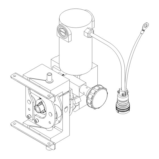
SECTION 4 − SPECIFICATIONS 4-1. Description Motor/drive Assembly This unit is a heavy-duty wire feed- ing motor/drive assembly designed for automated Submerged Arc Welding (SAW) applications. Motor shown without feed roller guard. Ref. 265710-A 4-2. Serial Number And Rating Label Location The serial number and rating information for this product is located on the motor body. -
Page 15: Overall Dimensions
4-5. Overall Dimensions Inches Millimeters 12-5/8 Motor shown without feed roller guard. 1/4 in.−20 UNC 2B THRD .500 in. Deep 11.000 in. 3.000 in. .750 in. .638 in. 2.000 in. 2.375 in. 5.325 in. Ref. 265710-A / Ref. 254235-B OM-253789 Page 11... -
Page 16: Section 5 − Installation
SECTION 5 − INSTALLATION 5-1. Installing Wire Guide And Drive Roll When changing wire size or type, check drive roll size (see Table 5-1). Wire Pressure Adjustment Screw Loosen screw to decrease tension on spring. Drive Roll Nut Drive Roll (Not Supplied) Remove drive roll. -
Page 17: Threading And Feeding Welding Wire
5-4. Threading And Feeding Welding Wire Hold wire tightly to keep it from unraveling. Tools Needed: Set power switches on the pow- er source and interface to On. 6 in. (150 mm) Pull and hold wire; cut off end. WIRE ADVANCE Motor shown without feed roller guard. -
Page 18: Manually Changing Feed Plate Angle
5-6. Manually Changing Feed Plate Angle Adjusting Knob Turn adjusting knob to change torch angle. Hub Clamp Screw Tighten screw. Feed Plate Screw Loosen screw. The feed plate maximum tilt angle is about 15 degrees from center in both directions. Tools Needed: 1/4 in. -
Page 19: Location Of Torch For Tandem Arc Applications
5-7. Location Of Torch For Tandem Arc Applications Follow instructions below to change torch to right of center or left of center. Assembly As Shipped (With torch right of center) Tools Needed: 1/4, 3/16 in. Motor shown without Torch Left Of Center Torch Right Of Center feed roller guard. -
Page 20: Section 6 − Maintenance And Troubleshooting
SECTION 6 − MAINTENANCE AND TROUBLESHOOTING 6-1. Routine Maintenance Disconnect power before maintaining. 3 Months Clean Repair Or Replace Replace Unreadable Tighten Cracked Labels Weld Weld Terminals Cable Replace Cord Cracked Hose Cable Parts 6 Months Blow Out Or Clean Vacuum Inside. -
Page 21: Troubleshooting
6-3. Troubleshooting Trouble Remedy Electrode wire feeding stops or feeds Readjust hub tension and drive roll pressure. erratically during welding. Change to correct size drive roll. Clean or replace dirty or worn drive roll. Check and replace incorrect size or worn wire guides. Replace contact tip or liner. -
Page 22: Section 8 − Parts List
SECTION 8 − PARTS LIST Hardware is common and not available unless listed. Shown For Reference See Figure Table 8-1 For Replacement Drive Rolls Ref. 254617-C Figure 8-1. Wire Drive Assembly Quantity Item Part Description 300938001 Figure 8-1. Wire Drive Assembly . - Page 23 Quantity Item Part Description 300938001 Figure 8-1. Wire Drive Assembly (Continued) ..198484 ....Insulator, Motor Subarc ......... . .
- Page 27 Effective January 1, 2017 (Equipment with a serial number preface of MH or newer) This limited warranty supersedes all previous Miller warranties and is exclusive with no other guarantees or warranties expressed or implied. Warranty Questions? LIMITED WARRANTY − Subject to the terms and conditions below, 6 Months —...
- Page 28 Contact the Delivering Carrier to: File a claim for loss or damage during shipment. For assistance in filing or settling claims, contact your distributor and/or equipment manufacturer’s Transportation Department. © ORIGINAL INSTRUCTIONS − PRINTED IN USA 2017 Miller Electric Mfg. Co. 2017−01...
Need help?
Do you have a question about the SUBARC WIRE DRIVE 400 T CE and is the answer not in the manual?
Questions and answers