Advertisement
Quick Links
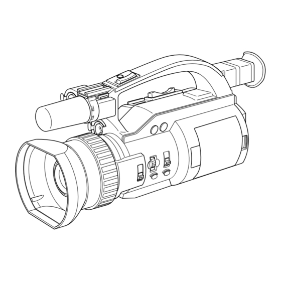
DV CAMCORDER
DV CAMKORDER
CAMESCOPE DV
GY-DV300
GY-DV301
Thank you for purchasing this JVC product. Before operating
this unit, please read the instructions carefully to ensure the
best possible performance.
INSTRUCTION MANUAL
BEDIENUNGSANLEITUNG
MANUEL D'INSTRUCTIONS
This instruction manual is made from 100% recycled paper.
LWT0055-001A
Advertisement

Related Manuals for JVC GY-DV301


Summary of Contents for JVC GY-DV301
- Page 1 CAMESCOPE DV GY-DV300 INSTRUCTION MANUAL BEDIENUNGSANLEITUNG GY-DV301 MANUEL D’INSTRUCTIONS Thank you for purchasing this JVC product. Before operating This instruction manual is made from 100% recycled paper. this unit, please read the instructions carefully to ensure the best possible performance. LWT0055-001A...
- Page 2 Thank you for purchasing the JVC GY-DV300 Camcorder. These instructions are for the GY-DV300E and GY-DV301E. The text mainly deals with the GY-DV300E. Explanations concerning unique GY-DV301E functions are set off by the (GY-DV301 only) notice. (IEEE1394 input is possible with the GY-DV301E.) These instructions are for the GY-DV300E and GY-DV301E.
- Page 3 SAFETY PRECAUTIONS WARNING: AVERTISSEMENT : TO REDUCE THE RISK OF FIRE OR POUR EVITER RISQUES ELECTRIC SHOCK, DO NOT EXPOSE D’INCENDIE OU D’ELECTROCUTION, THIS APPLIANCE TO RAIN OR NE PAS EXPOSER L’APPAREIL A MOISTURE. L’HUMIDITE OU A LA PLUIE. This unit should be used with 7V DC only. Ce magnétoscope ne doit être utilisé...
- Page 4 ● Recorded video and audio contents are for private use. Other use may infringe on the rights of copyright holders. ● JVC cannot assume liabilities that may derive from the impossibility of normal recording or playback of video or audio due to malfunction of the camcorder or the videocassette.
- Page 5 MAIN FEATURES ● Newly developed built-in 12-bit DSP employed ● Network connection possible (requires for high-quality picture installation of the optional network pack KA- ● High quality picture with 400% dynamic range DV300) ● Compact, lightweight design This allows audio and video streaming data to ●...
- Page 6 CONTENTS INTRODUCTION MANUAL ADJUSTMENTS Precautions for Proper Use ......7 Manual Focus Adjustment ....... 63 Routine and Periodical Maintenance ....9 Using ND Filter ..........65 Precautions for Use of Head Cleaning Tape ... 10 Obtaining Natural Tint (White Balance) ... 66 Videocassette to be Used .......
- Page 7 INTRODUCTION Precautions for Proper Use ● Supply voltage Make sure that the power is between 6 V and 12 V DC. If the power voltage is too low, abnormal colour and increased noise may occur. Do not exceed 12 V DC in any case, or the unit could be damaged. ●...
- Page 8 INTRODUCTION Precautions for Proper Use (Cont’d) ● When the unit is not in use, be sure to set the POWER switch to OFF in order to reduce power consumption. ● Cleaning the camera body: Wipe the body with a dry, soft cloth. When it is extremely dirty, soak the cloth in a solution of neutral detergent, wring it out and then wipe.
- Page 9 For details, see “Displaying the Hour Meter Display” on page 104. For consultations related to the maintenance programming or cost, please contact the person HEAD CLEANING in charge of professional video equipment at REQUIRED! your nearest JVC-authorized service agent.
- Page 10 5 hours every 20 to 30 hours every 5 hours tape Videocassette to be Used ● Use JVC videocassette tapes marked with Rewind it to the beginning before placing a MiniDV for this unit. cassette into storage.
- Page 11 Condensation ● When condensation occurs in this unit, the “VTR ● If the unit has been cooled down in a cold place WARNING (DEW)” appears on the LCD screen and is then carried to a warm place, the moisture contained in the warm air may adhere to the head and the viewfinder screen.
- Page 12 CONTROLS, Right Side Section INDICATORS AND CONNECTORS CH-1 CH-2 AUDIO LEVEL ND FILTER IRIS FOCUS AUTO MANU DV CAMCORDER GY-DV300 PUSH AUTO 1 FOCUS ring When the AUTO mode is selected for the iris Manual focus ring. adjustment, this dial can be rotated to adjust the Set the FOCUS switch 5 to “MANUAL”...
- Page 13 6 [FOCUS PUSH AUTO] Focus push auto button B Tally lamp Pressing this button when the MANUAL mode This lamp lights up red when the GY-DV300 is is selected for the focus adjustment engages in the recording mode. It blinks slowly When the the forced auto focus mode as long as the button battery pack is exhausted, or when there is about is pressed.
- Page 14 CONTROLS, Rear Section INDICATORS AND CONNECTORS POWER MODE PUSH CAM-B CAM-A GAIN SHUTTER MENU AUDIO CH-1 CH-2 MIC1 MIC2 MONITOR CH-1 CH-2 C [POWER] POWER switch “VTR”. When set to “CAM-A” or “CAM-B” in the Turn the power ON and OFF with this switch. shooting mode, two separate sets of setting values for recording can be set by means of the D Battery holder...
- Page 15 ● When the AE (Auto Exposure) function is OFF Selections and settings in the menu are performed with the SELECT dial L. and this button is pressed, the condition of the current gain setting is shown on the LCD The normal screen returns when this button is screen or the viewfinder screen for about 3 pressed while the MENU setting screen is seconds.
- Page 16 CONTROLS, Rear Section (cont’d) INDICATORS AND CONNECTORS LCD door storage compartment O [BAR] Colour bar/Playback & still button setting mode is displayed for about 3 seconds. ● Pressing this button in the shooting mode When the button is then pressed for 1 second switches the setting between colour bar output or more, the white balance adjustment starts.
- Page 17 ● Pressing this button simultaneously with the REV button R during stop in the VTR playback mode initiates the blank search mode (for locating the end point of recordings). R [REV] REVERSE/REW button ● Pressing this button in the shooting mode engages playback in reverse direction at normal speed for as long as the button is pressed.
- Page 18 CONTROLS, Left Side Section INDICATORS AND CONNECTORS MIC 1 IN MIC 2 IN U [VIDEO OUT] Video output connector (RCA) W [CH-1/CH-2 LINE OUT] CH-1/CH-2 audio Output connector for composite video signal. output connector (RCA) Outputs the input video signal and playback Output connector for audio signal.
- Page 19 DV connector can be connected here. To record DV signals (IEEE1394 signals) from this connector, the MODE switch H should be set to “VTR”. (GY-DV301 only) Memo: The GY-DV300 is not capable of recording DV signals (IEEE1394 signals).
- Page 20 CONTROLS, Front Section INDICATORS AND CONNECTORS \ Built-in microphone ` [MIC 2] Microphone 2 input connector (XLR- Built-in monaural microphone. ● To use this microphone, set the MIC INPUT Connect an external microphone to this SEL item to INT on the SYSTEM [1/2] menu connector.
- Page 21 CONTROLS, Top Section INDICATORS AND CONNECTORS EJECT VOLUME a ZOOM/Playback sound level adjustment c [ZOOM] Zoom lever lever Lever for zoom operation from the handle top ● This works as the zoom lever in the shooting section. ● In the shooting mode, pressing this lever in mode.
- Page 22 Indications on LCD Screen CONTROLS, and Viewfinder Screen INDICATORS AND CONNECTORS In addition to the E-E picture and the playback picture, the following indications are displayed on the LCD screen and the viewfinder screen. Status screens (screens for use in checking the current camera settings) Event indications Alarm indications Menu setting screens...
- Page 23 Normal display in the shooting mode Item Contents Zoom ratio (Characters, Displayed during zoom operation. The characters indicate the wide- numeric value) angle (W) and telephoto (T) zoom positions. The numeric value indicates the approximate zoom ratio. Time code display Shows the time code (hours, minutes, seconds, frames).
- Page 24 Indications on LCD Screen and CONTROLS, Viewfinder Screen (Cont’d) INDICATORS AND CONNECTORS Item Contents Camera-shake Displayed when the camera-shake compensation function is compensation on (OIS item on the OPERATION menu screen is set to ON). indication Manual focus indication MF: Displayed when manual focusing is enabled (when the FOCUS switch is set to MANUAL).
- Page 25 Item Contents Shooting mode Indicates whether the shooting mode is AUTO or MANUAL. Å: Displayed when the shooting mode is AUTO (when the MODE item indication is set to AUTO on the TOP MENU screen). ˜: Displayed when the shooting mode is MANUAL (when the MODE item is set to MANUAL on the TOP MENU screen).
- Page 26 Indications on LCD Screen and CONTROLS, Viewfinder Screen (Cont’d) INDICATORS AND CONNECTORS Vertically inverted display indications in the shooting mode Remaining battery power indication The remaining battery power is indicated by four different indicators. : Fully charged battery : Remaining battery power is low : No remaining battery power (blinking) VTR operation mode indication...
- Page 27 VTR playback mode status indications VOL. PL AY Item Contents Audio playback volume Displayed in the VTR mode. Characters indicate the high and low of indication the playback volume. Time code indication The recorded time code data (hours, minutes, seconds, frames) are shown here in the playback mode.
- Page 28 Indicates status of VTR operation. (STOP, PLAY, FF, REW, EJECT, STBY, FWD, REV, BSRH) DV signal indication DV : Displayed when IEEE1394 signal is recorded from the DV (GY-DV301 only) connector. Audio sampling The audio sampling frequency by which the recording was made is frequency indication displayed during playback.
- Page 29 Event Indications When the gain and shutter speed are changed manually, the set condition is displayed for about 3 seconds at the time the change is made. Event display area Event display area Set Condition Contents of Indication When the gain value is changed GAIN -3dB to 18dB (1dB step) When the LOLUX gain mode is selected LOLUX...
- Page 30 Displayed when an unrecordable videocassette (the switch on the back of the cassette is set to “SAVE”) is loaded. 1394 INHIBIT (GY-DV301 only) Displayed if an attempt to record is made when no DV signal is input. COPY INHIBIT Displayed when attempt to record a copy-guard protected signal is made.
- Page 31 MENU Setting Screen Used for making a variety of settings. See “MENU MEN U Setting Screen” on page 86. MODE E A R PHON E L V S Y S T EM S E T . . D I S P L AY S E T . . C A ME RA S E T [ C A - M A .
- Page 32 Basic System PREPARATIONS MICROPHONE MV-P615U IEEE1394 CABLE MIC HOLDER MV-P618U IEEE1394 CABLE VIDEO LIGHT NETWORK PACK KA-DV300 DV CAMCORDER AC ADAPTER/ BATTERY CHARGER TELE CONVERSION LENS CH-1 CH-2 AUDIO LEVEL AA-P30 ND FILTER IRIS FOCUS AUTO MANU DV CAMCORDER GY-DV300 PUSH AUTO WIDE CONVERSION LENS...
- Page 33 Power Supply Preparation PREPARATIONS The GY-DV300 is operable with AC power supply or battery pack. AC Operation Use the optional AC Adapter/Charger AA-P30 as the AC power supply. The DC INPUT connector on the GY-DV300 accepts power voltage in the range of DC 6V to DC 12V. POWER lamp POWER switch To AC outlet...
- Page 34 Power Supply Preparation (cont’d) PREPARATIONS Battery Pack Operation Use the optional battery pack BN-V428 for battery pack operation. Charging the Battery Pack Before use the battery pack should be charged using AC outlet AC cord the optional AC Adapter/Charger AA-P30. Plug the AC cable of the AC Adapter/Charger into an AC outlet.
- Page 35 Battery Pack Operation (Cont’d) Remaining Battery Power Indication The remaining battery power condition can be checked TALLY lamp by the remaining battery power indication on the LCD screen and the TALLY lamp. The battery condition is indicated as shown in the table below.
- Page 36 Attaching the Microphone (optional) PREPARATIONS Using the optional KA-A33 microphone holder allows the optional microphone MV-P615U or MV-P618U (phantom microphone) to be attached. Mount the microphone holder on the microphone holder attachment base on the handle of the GY- DV300. How to Attach Microphone holder attachment base...
- Page 37 Turning the Power ON PREPARATIONS FOR OPERATION POWER switch MODE switch POWER MODE PUSH CAM-B CAM-A GAIN SHUTTER MENU AUDIO CH-1 CH-2 MIC1 MIC2 MONITOR CH-1 CH-2 Slide the POWER switch to “ON”. Power is now supplied to the unit. The GY-DV300 operation mode when the power is turned ON will differ depending on the setting of the MODE switch as described in the following: MODE Switch...
- Page 38 Cassette Loading PREPARATIONS FOR OPERATION Tape window Erasure-prevention switch Cassette holder EJECT VOLUME EJECT switch Cassette cover Videocassette Loading the Cassette Unloading the Cassette Use a videocassette tape marked MiniDV. In the recording-standby or STOP mode, slide ● To record, slide the switch on the back for use in the EJECT switch to the side and then fully open preventing accidental erasure to the “REC”...
- Page 39 LCD Screen Adjustment PREPARATIONS FOR OPERATION The LCD screen’s direction, angle, screen brightness, etc. can be adjusted. Viewing the LCD Screen Slide the LCD lock release lever toward the rear side to open the LCD door. The LCD door can easily be opened by holding at the top and bottom of the door.
- Page 40 Adjusting the Viewfinder PREPARATIONS FOR OPERATION Adjusting the Position of the Viewfinder To facilitate low-angle shooting, the viewfinder can be turned approximately 75° upward. Underside Diopter Adjustment Move the diopter adjustment knob on the underside of the viewfinder until the viewfinder screen image is clearly visible.
- Page 41 Setting, Displaying and Recording the Date and Time PREPARATIONS FOR OPERATION The date and time of the built-in clock should be set. Powered by the built-in rechargeable backup battery, the set date and time data are retained and continue to count even when the power is switched off. ●...
- Page 42 Setting, Displaying and Recording the Date and Time (cont’d) PREPARATIONS FOR OPERATION 1 Rotate the SELECT dial to align the cursor (f) with the item CLOCK/TC menu screen to be set, and then press the SELECT dial. C LOCK T C ●...
- Page 43 : The date and time of the internal clock are displayed. During DV signal input : The date and time from the DV Time (GY-DV301 only) connector are displayed. Recording the Date and Time Data To record the date and time during shooting, set the following menu items.
- Page 44 Charging the Built-in Battery PREPARATIONS FOR OPERATION The built-in, rechargeable backup battery retains the date and time and the time code data. The built-in battery is constantly being charge whenever the GY-DV300 is connected to a power supply, but it gradually discharges while the GY-DV300 is disconnected from a power supply.
- Page 45 Setting, Displaying and Recording the Time Code PREPARATIONS FOR OPERATION Time code data should be set in the built-in time code generator. User’s bits cannot be set. During recording, the time code is automatically recorded on the tape. When recording starts from the beginning of the tape, recording starts from the set time code. Presetting the Time Code MENU button...
- Page 46 In VTR playback mode : The time code recorded on the tape is displayed. During DV signal recording : The current value of the built-in time (GY-DV301 only) code generator is displayed. Recording the Time Code The time code is recorded on the tape during recording. The time code formats are fixed as regeneration mode.
- Page 47 Shooting Mode SETTINGS BEFORE (Auto/Manual) Selection SHOOTING MODE switch MODE CAM-B CAM-A GAIN SHUTTER MENU TOP MENU screen The GY-DV300 is provided with two positions, “CAM-A” and “CAM- B”, for registering mode settings for camera shooting. MEN U Settings made on separate menu screens for camera shooting can MODE E A R PHON E L V be allocated to each of the “CAM-A”...
- Page 48 Shooting Mode (Auto/Manual) SETTINGS BEFORE Selection (cont’d) SHOOTING How to Select Either MANUAL or AUTO Shooting Mode MODE MODE switch CAM-B MENU CAM-A button GAIN SHUTTER MENU SELECT dial TOP MENU screen Set the MODE switch to the “CAM-A” or “CAM-B” position. MEN U MODE Press the MENU button to display the TOP MENU screen.
- Page 49 SETTINGS BEFORE Audio Input Signal Selection SHOOTING The GY-DV300 is provided with three sources for audio input (i.e., built-in microphone and input connectors MIC 1 and MIC 2 for external microphones). Two channels of sound can be recorded on the tape in digital PCM format. Select for each channel (CH1 and CH2) which sound should be recorded on the channel.
- Page 50 SETTINGS BEFORE Audio Input Signal Selection (cont’d) SHOOTING Setting Whether Phantom Microphone Should be used as External Microphone When a microphone (phantom microphone) requiring +48V DC SYSTEM [1/2] menu screen power supply is connected, set the +48V MIC1 or +48V MIC2 items on the SYSTEM [1/2] menu screen.
- Page 51 SETTINGS BEFORE Audio Monitor Selection SHOOTING POWER MODE PUSH CAM-B CAM-A GAIN SHUTTER MENU AUDIO CH-1 CH-2 MIC1 MIC2 MONITOR CH-1 CH-2 EARPHONE jack MONITOR CH-1 CH-2 MONITOR switch The audio input in the shooting mode can be monitored through an earphone or headphones connected to the EARPHONE jack.
- Page 52 SETTINGS BEFORE Focus Mode Selection SHOOTING FOCUS AUTO MANU CH-1 CH-2 PROFESSINAL AUDIO LEVEL PUSH AUTO ND FILTER IRIS FOCUS AUTO MANU DV CAMCORDER GY-DV300 PUSH AUTO FOCUS switch FOCUS ring The FOCUS switch is used to select whether focus adjustment should take place in the auto mode or the manual mode.
- Page 53 SETTINGS BEFORE Angle of View (Zoom In/Zoom Out) SHOOTING Handle ZOOM lever VOLUME ZOOM lever The ZOOM lever is used for zoom-in and zoom-out operations. Zooming can be performed using either the ZOOM lever on the top section of the GY-DV300 or the ZOOM lever on the top of the handle section.
- Page 54 SETTINGS BEFORE Menu Screen Settings SHOOTING The various conditions under which shooting should take place are set on the SYSTEM menu screen. The SYSTEM menu screen consists of two screens. (The SYSTEM menu screen settings must be made regardless of whether the AUTO or MANUAL shooting mode is used.) MODE MODE switch...
- Page 55 Contents of Settings on the SYSTEM [1/2] Screen Item Contents of Setting MIC1 INPUT SEL Selects whether the built-in microphone or a microphone connected to the MIC 1 input connector should be used. INT : Use this setting when the built-in microphone should be used. XLR : Use this setting when a microphone connected to the MIC 1 input connector should be used.
- Page 56 SETTINGS BEFORE Menu Screen Settings (cont’d) SHOOTING Contents of Settings on the SYSTEM [2/2] Menu Screen Item Contents of Setting FADER Sets whether fade is performed when recording is started and stopped. : No fade. BLACK : Fade in from black screen when recording is started; fade out to black screen when recording is stopped.
- Page 57 Basic Recording Operation SHOOTING ZOOM lever Handle REC START /STOP button POWER POWER switch MODE switch MODE CAM-B CAM-A EJECT switch GAIN SHUTTER ZOOM lever Cassette cover REC START/STOP button ● Setting the recording mode This section explains the basic recording procedures when the AUTO (AUTO/MANUAL) mode is selected as the shooting mode.
- Page 58 Basic Recording Operation (cont’d) SHOOTING ● ZOOM lever Point the camera at the subject and determine the angle of view A ZOOM lever is provided in two with the ZOOM lever. positions: one on the top section Adjusting the focus of the unit, and the other on top ●...
- Page 59 Viewing the Recorded Scene (Edit Search) SHOOTING The recorded scene can be checked and the position for recording the next scene can be searched in the recording-standby mode. FWD button REV button Enter the recording-standby mode Screen indication during edit search To advance the tape in forward direction.
- Page 60 If the Unit is Left in Recording-Standby Mode SHOOTING When the recording-standby mode has continued for about 30 Setting the time before the tape minutes, the GY-DV300 automatically stops drum rotation in order protection mode is engaged to protect the tape. (Tape protect mode) ●...
- Page 61 Recording the Color Bar SHOOTING BAR button It can be selected whether the camera image should be output or Color bar signal of the built-in whether the color bar of the built-in signal generator should be output signal generator during recording-standby and recording. An EBU standard color bar is The color bar is output when the BAR button is pressed while output.
- Page 62 Using the AE (Automatic Exposure) Function SHOOTING In addition to the automatic shooting mode, the GY-DV300 also offers the use of the AE (Automatic Exposure) function. The AE function combines the following three functions to automatically adjust the video signal level to their optimum levels. Gain : ALC (Auto Level Control) Shutter Speed : EEI...
- Page 63 Manual Focus Adjustment MANUAL ADJUSTMENTS IRIS FOCUS FOCUS AUTO switch MANU PUSH AUTO FOCUS ring In accordance with the conditions under which the subject is recorded, adjust the focus in the manual focus mode. In the auto focus mode, correct focus may be difficult to obtain under the following shooting conditions. ●...
- Page 64 Manual Focus Adjustment (Cont’d) MANUAL ADJUSTMENTS Momentarily Using Auto Focus It is possible to momentarily use the auto focus function while in the manual focus mode. IRIS FOCUS AUTO MANU PUSH AUTO PUSH AUTO FOCUS button Operation ● When the FOCUS switch is set Press the PUSH AUTO FOCUS button.
- Page 65 Using ND Filter MANUAL ADJUSTMENTS When the shooting conditions are too bright, the ND-filter can be used to reduce the brightness to an appropriate level. The built-in ND-filter can adjust the brightness to about 1/32 of the original. ND FILTER switch Operation ●...
- Page 66 Obtaining Natural Tint (White Balance) MANUAL ADJUSTMENTS The auto white balance function of the GY-DV300 automatically makes adjustments to obtain natural tint. However, depending on the shooting conditions or the light source, sometime it may not be possible to obtain natural tint with this function. In this case, the manual white balance adjustment should be used. The result of manual white balance adjustment is stored in one of the GY-DV300’s 3 types of memories.
- Page 67 2. Manual White Balance Adjustment • White balance adjustment is Set the ND FILTER switch in accordance with the lighting conditions. inhibited when PRESET is selected. The colour temperature Place a white object (white paper, etc.) near the centre of the screen and zoom in to fill the screen with white.
- Page 68 Manual Iris Adjustment MANUAL ADJUSTMENTS Adjust the iris (lens opening) manually in the following cases. ● For backlight compensation ● When the subject is too bright compared with the background ● When panning quickly from a bright place to a dark place 1.
- Page 69 2. Manual Iris Adjustment IRIS FOCUS AUTO MANU PUSH AUTO IRIS dial PUSH AUTO IRIS button Rotate the IRIS dial. The iris value (F-value) can be adjusted from CLOSE to F1.6. Rotating the dial upward opens the iris, and rotating it downward closes the iris.
- Page 70 Manual Shutter Speed Adjustment MANUAL ADJUSTMENTS The shutter speed can be adjusted manually to obtain special effects or when shooting a fast-moving subject. The shutter speed can also be adjusted manually in the variable scanning mode rate for shooting computer monitor screens. 1.
- Page 71 2. Adjusting the Shutter Speed Manually SHUTTER button GAIN SHUTTER MENU SELECT dial Press the SHUTTER button. ● The currently set shutter speed is shown for about 3 seconds on the LCD screen and the viewfinder screen. SHUTTER 1/1000 ● The shutter speed can be set while the shutter speed value is displayed.
- Page 72 Manual Gain Adjustment MANUAL ADJUSTMENTS Using the ALC (Auto Level Control) function, the GY-DV300 automatically adjusts the gain (sensitivity) in accordance with the brightness of the subject. However, if the lighting conditions are poor and where the illumination is insufficient, it is possible to adjust the gain manually. 1.
- Page 73 2. Adjusting the Gain Manually GAIN button GAIN SHUTTER MENU SELECT dial Press the GAIN button. ● The currently set gain value is shown for about 3 seconds on the LCD screen and the viewfinder screen. + 6 d B ●...
- Page 74 Manual Gain Adjustment (cont’d) MANUAL ADJUSTMENTS 3. Engaging the LOLUX Mode with the GAIN Button In the auto or manual gain adjustment mode, the LOLUX mode can be entered directly by operating the GAIN button. GAIN button GAIN SHUTTER MENU About the LOLUX mode Operation Used when the brightness is still...
- Page 75 Displaying Zebra Patterns for Adjustment MANUAL ADJUSTMENTS Zebra patterns are oblique stripes than can be displayed to indicate very bright areas of the screen. Areas where zebra patterns are indicated are likely to be blurred with white if left unadjusted. The zebra patterns can be used as a reference for manual adjustment of the brightness to adjust to the optimal level.
- Page 76 Manual Adjustment of the Audio Recording Level MANUAL ADJUSTMENTS The audio recording level can be manually adjusted during shooting. The audio recording level can be adjusted separately for the CH-1 and CH-2 channels. 1. Engaging the Manual Audio Recording Level Adjustment Mode MENU button GAIN...
- Page 77 2. Adjusting the Audio Recording Level Manually CH-1 CH-2 AUDIO LEVEL AUDIO LEVEL controls ● The standard level for recording Turn the AUDIO LEVEL controls. audio on the tape is –12 dB. If a tape recorded on the GY- The audio recording level of CH-1 channel is adjusted with the DV300 is played back on VCR CH-1 AUDIO LEVEL control, and the CH-2 channel is adjusted whose audio standard level is –...
- Page 78 Disabling Operation of the Camera- Shake Compensation Function MANUAL ADJUSTMENTS When shooting with the camera under conditions where the camera-shake compensation function is not required, e.g., with the camera mounted on a tripod base, etc., set the function to OFF before shooting. MENU button GAIN...
- Page 79 Adjusting the Quality of Camera Image MANUAL ADJUSTMENTS The GY-DV300 allows manual adjustment of the image quality of the camera image. By setting the various items on the CAMERA menu screen, you can make adjustments to obtain an image quality suiting your preference.
- Page 80 Playback of Tape PLAYBACK The recorded picture can be viewed on the LCD screen or in the viewfinder. The playback sound is not output from the monitoring speaker of the GY-DV300. MODE MODE switch POWER switch CAM-B BAR (f/ w) CAM-A button AW (a)
- Page 81 Fast-Forward, Rewind (h) ● Fast-forward and rewind may Press the FWD (g) button in stop mode to fast forward the take longer than normally under tape. Press the REV (h) button in stop mode to rewind the cold conditions. tape. Press the AW (a) button to stop fast forwarding or rewinding.
- Page 82 Adjusting the Playback Sound Volume PLAYBACK AUDIO OUT connector Built-in speaker EARPHONE jack VOLUME ZOOM lever The level of the playback sound can be controlled with the ZOOM Playback audio volume lever on the top section of the GY-DV300. Pressing the lever toward the TELE (+) side raises the playback VOL.
- Page 83 Outputting CH-3/CH-4 Channel Sound PLAYBACK 4 channels are available when the DV format is recorded with 12-bit, 32 kHz audio sampling. The GY- DV300 records audio on the CH-1 and CH-2 channels. When the GY-DV300 is used for playback of tapes with sound recorded on the CH-3 and CH-4 channels on another unit, the PB AUDIO SELECT item on the VTR menu screen must be set.
- Page 84 ● Audio noise may be heard when turning on/off the device connected to the DV connector or when switching video input. When performing these types of operations, turn the volume of the audio device, speakers, etc., connected to GY-DV301 to minimum. E-84...
- Page 85 When using the GY-DV301 as recording unit (dubbing from another videocassette) Date and time data: Data sent Connect the units with the DV cable. from the playback unit is recorded. Turn ON both units. Time code: The data generated by the GY-DV301’s time code...
- Page 86 MENU Screen Structure (Shooting Mode) MENU SCREEN The MENU consists of multiple layers of menu screens. The following shows the MENU screen structure when the MODE switch on the rear section is set to “CAM-A” or “CAM-B”. Separate menu screens are displayed for each position of the MODE switch (“CAM-A”...
- Page 87 0 2 0 TOP MENU screen SYSTEM menu screen MEN U (GY-DV301 only) REC MODE V T R S E T . . S Y S T EM S E T . . LONG P AU S E T I ME...
- Page 88 Setting Menu Screens MENU SCREEN Various settings are made on the menu screens in accordance with the mode of usage of the GY-DV300. In the shooting mode, settings can be made on two separate sets of menus in accordance with the setting of the MODE switch (“CAM-A”...
- Page 89 SYSTEM [1/2] menu screen Changing the set value. Rotate the SELECT dial to change the setting, and then press E M 1 / 2 ] the SELECT dial. M I C 1 I NP U T S E L W I N D C U T M I C 1 OF F ●...
- Page 90 Contents of Menu Screens MENU SCREEN Different menu screens are displayed depending on whether the GY-DV300 is in the shooting mode or in the VTR playback mode. The setting values marked with the ● symbol in the explanations of the menu screens are the factory settings.
- Page 91 The displayed menu screens of the SYSTEM Menu Screen differ with the shooting mode and the VTR mode. SYSTEM Menu Screen (Shooting mode) In the shooting mode, the SYSTEM Menu Screen consists of two screens. (1/2 screen and 2/2 screen) SYSTEM 1/2 screen Item Set Value...
- Page 92 Contents of Menu Screens (cont’d) MENU SCREEN SYSTEM Menu Screens (Shooting mode) (Cont’d) Item Set Value Contents LONG PAUSE 3 MIN Selects the time (minutes) before the tape protection mode is ● 30 MIN TIME engaged when the recording-standby mode or still mode continues.
- Page 93 When used in a cold environment, this becomes 3 minutes regardless of the setting. TALLY Selects whether or not the TALLY lamp should light when (GY-DV301 only) ● ON recording DV signals. OFF : The TALLY lamp does not light. ON : The TALLY lamp lights.
- Page 94 Contents of Menu Screens (cont’d) MENU SCREEN DISPLAY Menu Screen The DISPLAY Menu Screen consists of two screens (1/2 Screen and 2/2 Screen). DISPLAY [1/2] Menu Screen Item Set Value Contents ● OFF ZEBRA Selects whether zebra patterns should be shown on the LCD 70 –...
- Page 95 DISPLAY Menu Screen (cont’d) Item Set Value Contents TIME/DATE DISP+REC Selects whether the date and time should be shown on the LCD ● DISPLAY screen or the viewfinder screen, and whether the indications should be recorded on the tape. DISP+REC : Displayed on the LCD screen or the viewfinder When the mode switch is set screen and recorded on the tape.
- Page 96 Contents of Menu Screens (cont’d) MENU SCREEN CAMERA Menu Screen The CAMERA menu screen can only be set in the shooting mode. The position (“CAM A” or “CAM B”) of the MODE switch is indicated after the menu title name. Item Set Value Contents...
- Page 97 CAMERA Menu Screen (Cont’d) Item Set Value Contents ● NORMAL BLACK Selects the gain for the dark section of the image. Set to an STRETCH appropriate position in accordance with the subject. COMPRESS NORMAL : Standard mode. STRETCH : By stretching the signal only for the dark section, contrast in the dark portion of the image is enhanced.
- Page 98 Contents of Menu Screens (cont’d) MENU SCREEN OPERATION Menu Screen The OPERATION menu screen can only be set in the manual shooting mode. The position (“CAM A” or “CAM B”) of the MODE switch is indicated after the menu title name. The item values set off by the symbol are the factory settings when the MODE switch is set to CAM-A.
- Page 99 CLOCK/TC Menu Screen Item Set Value Contents TC PRESET The screen for setting the time code appears when the SELECT dial is pressed. ( See page 45.) CLOCK The screen for setting the date and time appears when the ADJUST SELECT dial is pressed.
- Page 100 “SAVE”) is loaded. 1394 INHIBIT Displayed if an attempt to record is Input the DV signal. (GY-DV301 only) made when no DV signal is input. COPY INHIBIT Displayed when attempt to record A copy-guard protected signal cannot be a copy-guard protected signal is recorded.
- Page 101 “ON” again. In some cases, however, the tape may be damaged. Please consult the person in charge of professional video equipment at your nearest JVC-authorized service agent. VTR WARNING The tape is cut Operation : Operation stops. (TAPE) Remedy : Take out the cassette tape.
- Page 102 In Case of Difficulty TROUBLESHOOTING Symptoms Troubles, Checks and Remedial Actions Power cannot be switched ON. • Is power supply connected properly? • Is battery pack charged? • Was the power turned ON immediately after being turned OFF? Wait at least 5 seconds before turning the power ON again once it has been turned OFF.
- Page 103 • Is the MODE switch set to “VTR”? Input of DV signal is not possible if the switch is set to “CAM-A” or “CAM-B”. (GY-DV301 only) Cassette cannot be ejected after • The capacity of the power supply may be insufficient. Check the power is turned ON.
- Page 104 Displaying the Hour Meter Display OTHERS The GY-DV300 indicates the accumulated hours of drum running time by means of the HOUR METER displayed on the LCD screen or viewfinder screen. Display of the HOUR METER is selected by the DRUM HOUR item on the VTR menu screen. This is used as yardstick for periodical maintenance.
- Page 105 If dirt penetrates into the interior of viewfinder OTHERS If dirt penetrates into the viewfinder, take off the rubber ring from the base of the viewfinder and remove the dirt using a lens blower. Return the rubber ring to its original position after cleaning. Lens blower Remove rubber ring...
- Page 106 Installing the ferrite core OTHERS To retain electromagnetic compatibility, use ferrite cores provided when connecting to tha cables. There are two types of ferrite cores, a small and a medium sized type. Both should be attached at the cable end that is close to the camera. Ferrite core (small) DC cable DC cable...
- Page 107 Specifications OTHERS CAMERA SECTION Record/Play time : 60 minutes (With M- Image pickup devices : 1/3-inch interline CCD × 3 DV60ME cassette, SP Mode) Colour separation optical system : 90 minutes (With M- F1.6 3-colour separation DV60ME cassette, LP prism Mode) Number of effective pixels : F.F/Rewind time...
- Page 108 Specifications (cont’d) OTHERS GENERAL Power consumption : 7.2 V — 2.0A Mass : Approx. 1.4 kg (without battery) Allowable operating temperatures : 0 °C to 40 °C Allowable operating humidity : 30% to 80% RH Allowable storage temperatures : –20 °C to 60 °C ACCESSORIES Instruction Manual : x 1 Ferrite core...
- Page 109 EXTERNAL DIMENSIONS (unit: mm) CH-1 CH-2 AUDIO LEVEL ND FILTER IRIS FOCUS AUTO MANU DV CAMCORDER GY-DV300 PUSH AUTO E-109...
Need help?
Do you have a question about the GY-DV301 and is the answer not in the manual?
Questions and answers