Advertisement
Quick Links
INSTALLATION
INSTRUCTION
TABLE OF CONTENTS
GENERAL INFORMATION . . . . . . . . . . . . . . . . . 2
INSPECTION . . . . . . . . . . . . . . . . . . . . . . . . . . . . . . . . . 2
REFERENCE . . . . . . . . . . . . . . . . . . . . . . . . . . . . . . . . 2
LIMITATIONS . . . . . . . . . . . . . . . . . . . . . . . . . . . . . . . . 2
UNIT INSTALLATION . . . . . . . . . . . . . . . . . . . . . 3
LOCATION . . . . . . . . . . . . . . . . . . . . . . . . . . . . . . . . . . 3
GROUND INSTALLATION . . . . . . . . . . . . . . . . . . . . . . 3
UNIT PLACEMENT . . . . . . . . . . . . . . . . . . . . . . . 3
TXV INSTALLATION . . . . . . . . . . . . . . . . . . . . . . . . . . . 3
PIPING CONNECTIONS . . . . . . . . . . . . . . . . . . . . . . . . 4
PRECAUTIONS DURING LINE INSTALLATION . . . . . 4
PRECAUTIONS DURING BRAZING OF LINES . . . . . . 5
PRECAUTIONS DURING BRAZING ANGLE VALVE . . 5
ELECTRICAL CONNECTIONS . . . . . . . . . . . . . . 6
GENERAL INFORMATION & GROUNDING . . . . . . . . . 6
POWER WIRING . . . . . . . . . . . . . . . . . . . . . . . . . . . . . . 6
ACCESSORY WIRING . . . . . . . . . . . . . . . . . . . . . . . . . 6
THERMOSTAT MOUNTING / WIRING . . . . . . . . . . . . . 6
DE-HUMIDIFICATION CONTROL . . . . . . . . . . . . . . . . 7
FIELD CONNECTIONS - CONTROL WIRING . . . . . . . 7
INDOOR BLOWER SPEED SETTINGS . . . . . . . 7
WIRING DIAGRAMS . . . . . . . . . . . . . . . . . . . . . . . . . . . 8
SYSTEM START-UP . . . . . . . . . . . . . . . . . . . . . . . . . . 10
CHECKING SYSTEM CHARGE . . . . . . . . . . . . . . . . . 10
SERVICING AND VERIFY: . . . . . . . . . . . . . . . . . . . . . 10
RECORDING TOTAL SYSTEM CHARGE . . . . . . . . . 10
SYSTEM FUNCTIONS . . . . . . . . . . . . . . . . . . . . 10
COOLING OPERATION . . . . . . . . . . . . . . . . . . . . . . . 11
SYSTEM CONTROL BOARD FUNCTIONS . . . . . . . . 12
INSTRUCTING THE OWNER . . . . . . . . . . . . . . 12
INDICATIONS OF PROPER OPERATION . . . . . . . . . 12
MAINTENANCE . . . . . . . . . . . . . . . . . . . . . . . . . . . . . . 12
CAUTION:READ ALL SAFETY GUIDES BEFORE
YOU START TO INSTALL YOUR UNIT.
SAVE THIS MANUAL
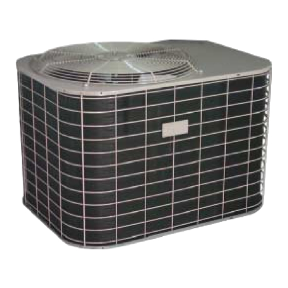
OUTDOOR SPLIT-SYSTEM
AIR CONDITIONER
12 SEER 2 TO 5 TONS
MODELS:
HATC-F024S
HATC-F030S
HATC-F036S
HATC-F048S
HATC-F060S
035-16399-001 Rev. B (101)
Advertisement

Related Manuals for York HATC-F024S


Summary of Contents for York HATC-F024S
- Page 1 CHECKING SYSTEM CHARGE ....10 MODELS: HATC-F024S SERVICING AND VERIFY: ..... 10 HATC-F030S RECORDING TOTAL SYSTEM CHARGE .
- Page 2 035-16399-001 Rev. B (101) GENERAL INFORMATION These outdoor condensing units are designed to be installed with corresponding variable speed air handlers or furnaces, two stage furnaces and single speed air handlers or furnaces Incorrect installation may create a condition and a corresponding coil with sweat connect lines. Each unit where the operation of the product could cause is factory charged with refrigerant sufficient for the smallest personal injury or property damage.
- Page 3 035-16399-001 Rev. B (101) MINIMUM 18” SERVICE ACCESS THERMOSTAT CLEARANCE ON ONE SIDE TO FURNACE OR 60” OVERHEAD AIR HANDLER CLEARANCE WEATHERPROOF TERMINAL BLOCK DISCONNECT SWITCH NEC CLASS 1 WIRING NEC CLASS 2 WIRING 10” CLEARANCE TO INDOOR COIL COIL AREA SEAL OPENING(S) WITH PERMAGUM OR EQUIVALENT NOTE: ALL OUTDOOR WIRING MUST...
- Page 4 035-16399-001 Rev. B (101) After orifice is removed, install the thermal expansion Bulb should be insulated using thermal insulation pro- valve to the orifice distributor assembly with supplied fit- vided to protect it from the effect of the surrounding tings. Hand tighten and turn an additional 1/8 turn to ambient temperature.
- Page 5 035-16399-001 Rev. B (101) PRECAUTIONS DURING BRAZING OF LINES The outdoor units have re-usable service valves on both the liquid and vapor connections. The total system refrigerant charge is retained within the outdoor unit during shipping and The evaporator is pressurized. installation.
- Page 6 035-16399-001 Rev. B (101) Energize the crankcase heater to save time by preheat- ing the compressor oil while the remaining installation is completed. ACCESSORY WIRING Never attempt to repair any brazed connections The electrical accessories available for this unit are a two while the system is under pressure.
- Page 7 035-16399-001 Rev. B (101) FIELD CONNECTIONS - CONTROL WIRING Single Speed Air Handlers and Furnaces - connections shown in Figures 5 and 6. It is mandatory to connect the The recommended field connections for specific indoor air appropriate blower relay to operate the low speeds. The first handlers and furnaces are shown in Figures 4 through 7.
- Page 8 035-16399-001 Rev. B (101) 2-SPEED FAN KIT HIGH (2SF06700124) HANDLER MOTOR 2-SPEED OUTDOOR UNIT L TRIP ECM CONTACTOR L1 FAN N-AH F*FC/F*FP WIRE NUT F*RP/F*RC MODELS THERMOSTAT GND. Y2 OUT DEHUMIDISTAT (OPTIONAL) TS CONTROL POWER (CLASS 1 WIRING) POWER WIRING CONTROL (CLASS 2 WIRING) TYPICAL TWO STAGE...
- Page 9 035-16399-001 Rev. B (101) OUTDOOR UNIT CONTACTOR P*DU, P*XU WIRE NUT 2-STAGE THERMOSTAT FURNACE GND. DEHUMIDISTAT (OPTIONAL) TS CONTROL (CLASS 1 WIRING) POWER CONTROL (CLASS 2 WIRING) TYPICAL TWO STAGE POWER WIRING COOLING THERMOSTAT FACTORY 208/230-1-60 MUST BE USED CONNECT FOR THERMOSTAT WITH FAULT DEHUMIDISTAT MAKES CIRCUIT ON LIGHT INDICATOR ONLY, CAPTHIS WIRE HUMIDITY RISE.
- Page 10 035-16399-001 Rev. B (101) INDOOR BLOWER SPEED SETTINGS Refer to the Tabular Data Sheet for the recommended air flow settings for each size condensing unit. Variable Speed Air Handlers and Furnaces - Set the high Refrigerant charging should only be carried out speed cooling speed per the instructions for the air handler or by a qualified air conditioning contractor.
- Page 11 035-16399-001 Rev. B (101) RECORDING TOTAL SYSTEM CHARGE A humidistat installed with a variable speed air handler or fur- nace reduces the airflow of the blower by 15% of the pro- The factory charge in the outdoor unit is listed on tabular data grammed speed during the dehumidification mode.
- Page 12 Subject to change without notice. Printed in U.S.A. 035-16399-001 Rev. B (101) Copyright © by York International Corp. 2001. All rights reserved. Supersedes: 035-16399-001 Rev. A (101) Unitary 5005...
Need help?
Do you have a question about the HATC-F024S and is the answer not in the manual?
Questions and answers