Table of Contents
Advertisement
Quick Links
Advertisement
Table of Contents

Summary of Contents for DMP Electronics 1100R Series
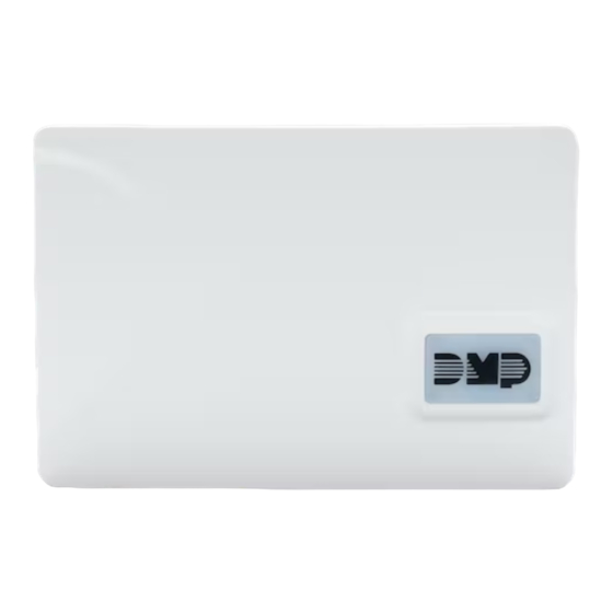
- Page 1 INSTALLATION AND PROGRAMMING GUIDE 1100R Series Wireless Repeater...
- Page 2 GET STARTED The 1100R Series Wireless Repeater increases the wireless communication range between the receiver and transmitters. The 1100RE features 128-bit AES encryption. Up to eight repeaters can be installed on a wireless system. The repeater is powered from a 12 VDC power supply and includes a 24-hour battery backup.
- Page 3 INSTALLATION Program the Panel After completing each of the following steps, press CMD to advance to the next option. Refer to the panel programming guide as needed. Reset the panel. At a keypad, enter 6653 (PROG) to access the PROGRAMMER menu. In ZONE INFORMATION, enter the wireless zone number from the table below.
- Page 4 Select a Location Mount the 1100R on a wall and away from large, metal objects. Mounting on or near metal surfaces impairs performance. The 1100R is typically mounted between the 1100 Series Wireless Receiver and the 1100 Series Wireless Transmitters that are out of range. Mount the 1100R as far from the 1100 Series Receiver as needed to provide the required system range.
- Page 5 Connect an External Power Supply 1100R DC Power Observe positive and negative polarity on all connections. Using a 22 AWG 4-position terminal block wire, connect the DC power terminal block to the DC terminal on the 505-12 power supply PCB. See Figure 4. 505-12 Power Supply Note: The DC plug-in power also charges the backup battery.
- Page 6 LISTED COMPLIANCE SPECIFICATIONS Commercial Fire After all transmitters are in position, the WLS option of the panel’s Walk Test must be operated and all transmitters programmed for Fire (FI) or Supervisory (SV) must show that their checkin message was received. Refer to the panel programming guide for Trip Counter for DMP Wireless check-in Test (WLS) which describes that both numbers of the counter must match.
- Page 7 Patents ▶ U.S. Patent No. 7, 239, 236 Certifications ▶ California State Fire Marshal (CSFM) ▶ FCC Part 15 Registration ID: CCKPCO114R6 CCKPC0245 ▶ Industry Canada: 5251A-PC0114R6 5251A-PC0245 ▶ New York City (FDNY) Underwriters Laboratory (UL) Listed ANSI/UL 365 Police Station Connected Burglar ANSI/UL 609 Local Burglar Alarm Units and Systems ANSI/UL 1023...


Need help?
Do you have a question about the 1100R Series and is the answer not in the manual?
Questions and answers