Advertisement
Quick Links
Model No. NTL15421-INT.2
Serial No.
USER'S MANUAL
Write the serial number in the space
above for reference.
Serial Number
Decal
CUSTOMER SERVICE
UNITED KINGDOM
Call: 0330 123 1045
From Ireland: 053 92 36102
Website: iconsupport.eu
E-mail: csuk@iconeurope.com
Write:
ICON Health & Fitness, Ltd.
Unit 4, Westgate Court
Silkwood Park
OSSETT
WF5 9TT
UNITED KINGDOM
AUSTRALIA
Call: 1800 993 770
E-mail: australiacc@iconfitness.com
Write:
ICON Health & Fitness, Inc.
PO Box 635
WINSTON HILLS NSW 2153
AUSTRALIA
CAUTION
Read all precautions and
instructions in this manual before
using this equipment. Keep this
manual for future reference.
iconeurope.com
Advertisement

Related Manuals for NordicTrack NTL15421-INT.2


Summary of Contents for NordicTrack NTL15421-INT.2
- Page 1 Model No. NTL15421-INT.2 Serial No. USER’S MANUAL Write the serial number in the space above for reference. Serial Number Decal CUSTOMER SERVICE UNITED KINGDOM Call: 0330 123 1045 From Ireland: 053 92 36102 Website: iconsupport.eu E-mail: csuk@iconeurope.com Write: ICON Health & Fitness, Ltd.
- Page 2 Note: The decals may not be shown at actual size. 305284 NORDICTRACK and IFIT are registered trademarks of ICON Health & Fitness, Inc. Wi-Fi is a registered trade- mark of Wi-Fi Alliance. WPA and WPA2 are trademarks of Wi-Fi Alliance. The Bluetooth word mark and logos ®...
- Page 3 IMPORTANT PRECAUTIONS WARNING: To reduce the risk of burns, fire, electric shock, or injury to persons, read all important precautions and instructions in this manual and all warnings on your treadmill before using your treadmill. ICON assumes no responsibility for personal injury or property damage sus- tained by or through the use of this product.
- Page 4 19. Always stand on the foot rails when starting 26. Do not change the incline of the treadmill by or stopping the walking belt. Always hold the placing objects under the treadmill. handrails while using the treadmill. 27. Never insert any object into any opening on 20.
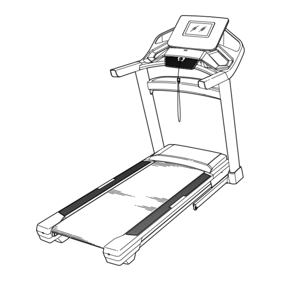
- Page 5 BEFORE YOU BEGIN Thank you for selecting the revolutionary reading this manual, please see the front cover of this NORDICTRACK EXP 10I treadmill. The EXP 10I manual. To help us assist you, please note the product ® treadmill offers an impressive selection of features model number and serial number before contacting us.
- Page 6 PART IDENTIFICATION CHART Use the drawings below to identify small parts used for assembly. The number in parentheses below each draw- ing is the key number of the part, from the PART LIST near the end of this manual. The number following the key number is the quantity used for assembly.
- Page 7 ASSEMBLY • Assembly requires two persons. • Left parts are marked “L” or “Left” and right parts are marked “R” or “Right.” • Place all parts in a cleared area and remove the packing materials. Do not dispose of the packing •...
- Page 8 2. Make sure that the power cord is unplugged. Remove the tie securing the Upright Wire (90) to the front of the Base (98). Next, identify the Right Upright (84). Have a second person hold the Right Upright near the Base (98).
- Page 9 4. Hold the Right Upright (84) against the Base (98). Make sure not to pinch the Upright Wire (90). Attach the Right Upright (84) and a Wheel (99) with two 3/8" x 2 3/8" Screws (5), a 3/8" x 1 1/4" Screw (7), a 3/8"...
- Page 10 6. Attach the Left and Right Handrails (81, 82) to the Left and Right Uprights (83, 84) with four 5/16" x 2 1/2" Screws (8) and four 5/16" Star Washers (12); do not fully tighten the Screws yet. Be careful not to pinch the Upright Wire (90) on the right side.
- Page 11 8. IMPORTANT: To avoid damaging the Crossbar (87), do not use power tools, and do not over- tighten the #10 x 3/4" Screws (4). Orient the Crossbar (87) as shown. Attach the Crossbar to the Handrails (81, 82) with four #10 x 3/4"...
- Page 12 10. Attach the console assembly (G) to the Handrails (81, 82) with four 1/4" x 1/2" Screws (21) that you removed in step 7 and four 1/4" Star Washers (37); start all four Screws, and then tighten them. Be careful not to pinch the wires (I).
- Page 13 12. Align the Right Top Handrail Cover (78) with the Crossbar (87) and with the holes (J) in the Right Handrail (82). Then, press the Right Top Handrail Cover downward onto the Right Handrail. The front of the Right Top Handrail Cover should flex around the Console Base (101) and snap into place around the Crossbar.
- Page 14 14. Attach the Tray (88) to the Upright Crossbar (89) with four #8 x 1/2" Screws (2); start all four Screws, and then tighten them. Do not over- tighten the Screws. 15. Note: If the treadmill is assembled on a smooth surface, it may roll forward during this step.
- Page 15 16. Remove the 5/16" Nut (36) and the 5/16" x 1 3/4" Bolt (26) from the bracket on the Base (98). Next, orient the Storage Latch (58) as shown. Attach the lower end of the Storage Latch (58) to the bracket on the Base (98) with the 5/16"...
- Page 16 18. Firmly tighten the four 3/8" x 2 3/8" Screws (5) and the two 3/8" x 1 1/4" Screws (7). Next, tighten the two 3/8" x 1 3/4" Screws (6); make sure that the Wheels (99) turn freely. Next, set the Left Inner Base Cover (96) onto the lower end of the Left Upright (83).
- Page 17 Dubai HOW TO USE THE TREADMILL HOW TO PLUG IN THE POWER CORD Follow the steps below to plug in the power cord. This product must be earthed. If it should malfunc- 1. Plug the indicated end of the power cord (A) into the tion or break down, earthing provides a path of least socket (B) on the treadmill.
- Page 18 CONSOLE DIAGRAM FEATURES OF THE CONSOLE exercise feedback. You can even measure your heart rate using a compatible heart rate monitor. See page The advanced treadmill console offers a selection of 28 for information about purchasing an optional features designed to make your workouts more effec- heart rate monitor.
- Page 19 HOW TO TURN ON THE POWER HOW TO USE THE TOUCH SCREEN IMPORTANT: If the treadmill has been exposed to The console features a tablet with a full-color touch cold temperatures, allow it to warm to room tem- screen. The following information will help you become perature before you turn on the power.
- Page 20 HOW TO SET UP THE CONSOLE 5. Check for firmware updates. Before using the treadmill for the first time, set up the First, touch your name or Hello on the screen, and then touch Settings. Next, select the maintenance console. section.
- Page 21 HOW TO USE THE MANUAL MODE 4. Change the incline of the treadmill as desired. 1. Insert the key into the console. To change the incline of the treadmill, press the Incline increase and decrease buttons or one of the See HOW TO TURN ON THE POWER on page 19.
- Page 22 6. Turn on the fan if desired. 3. Select a map workout. The fan features sev- To select a map workout, touch the desired option eral speed settings. on the screen. Note: The featured map workouts Press the fan buttons on your console will change periodically.
- Page 23 HOW TO USE A DRAW YOUR OWN MAP 4. Save your workout. WORKOUT Touch Save New Workout on the screen. If desired, Note: To use a draw your own map workout, the change the title of the workout or add a description, console must be connected to a wireless network (see and then press the >...
- Page 24 HOW TO USE A DISTANCE OR TIME WORKOUT 5. Select a distance or time workout that you have previously added to your schedule on iFit.com. Note: To use a distance or time workout, the console must be connected to a wireless network (see HOW Touch the calendar icon to download a distance or TO CONNECT TO A WIRELESS NETWORK on page time workout from your schedule.
- Page 25 HOW TO CHANGE CONSOLE SETTINGS 3. Customize the unit of measurement and other settings. IMPORTANT: Some of the settings and features described may not be enabled. Occasionally, a To customize the unit of measurement, the time firmware update may cause your console to function zone, or other settings, touch Equipment Settings, slightly differently.
- Page 26 6. Calibrate the incline system of the treadmill. HOW TO CONNECT TO A WIRELESS NETWORK Touch Calibrate Incline, and then touch Begin The console is Wi-Fi enabled, allowing you to set up a to calibrate the incline system. The treadmill will wireless network connection.
- Page 27 HOW TO USE THE SOUND SYSTEM An information box will ask if you want to connect to the wireless network. Touch Connect to connect to the network or touch Cancel to return to the list You can use any Bluetooth-enabled personal audio of networks.
- Page 28 HOW TO ADJUST THE CUSHIONS THE OPTIONAL HEART RATE MONITOR The treadmill features a cushioning system that Whether your reduces the impact as you walk or run on the treadmill. goal is to burn fat or to To adjust the cushions, first remove the key from the strengthen your console and unplug the power cord.
- Page 29 HOW TO FOLD AND MOVE THE TREADMILL HOW TO FOLD THE TREADMILL HOW TO MOVE THE TREADMILL To avoid damaging the treadmill, adjust the incline Before moving the treadmill, fold it as described at the to zero before you fold the treadmill. Then, remove left.
- Page 30 MAINTENANCE AND TROUBLESHOOTING MAINTENANCE SYMPTOM: The power turns off during use Regular maintenance is important for optimal perfor- a. Check the power switch (see drawing c at the left). mance and to reduce wear. Inspect and properly tighten If the switch has tripped, wait for five minutes and all parts each time the treadmill is used.
- Page 31 SYMPTOM: The displays of the console do not b. If the console does not boot up properly, or if the function properly console freezes and does not respond, reset the console to the factory default settings. IMPORTANT: Doing this will erase all the a.
- Page 32 SYMPTOM: The walking belt slows when walked on SYMPTOM: The walking belt is not centered between the foot rails a. If an extension cord is needed, use only a 3-con- a. IMPORTANT: If the walking belt rubs against the ductor, 14-gauge (2 mm ) cord that is no longer foot rails (F), the walking belt may become than 5 ft.
- Page 33 EXERCISE GUIDELINES Aerobic Exercise—If your goal is to strengthen your WARNING: cardiovascular system, you must perform aerobic Before beginning this exercise, which is activity that requires large amounts or any exercise program, consult your physi- of oxygen for prolonged periods of time. For aerobic cian.
- Page 34 PART LIST Model No. NTL15421-INT.2 R0321A Key No. Qty. Description Key No. Qty. Description M4 x 13mm Screw Idler Roller/Pulley #8 x 1/2" Screw Controller Clamp #8 x 3/4" Screw Controller Plate #10 x 3/4" Screw Plastic Tie 3/8" x 2 3/8" Screw Latch Crossbar 3/8"...
- Page 35 Key No. Qty. Description Key No. Qty. Description Console Base Hood Clip Left Tray Reed Switch Right Tray Clip Magnet Fan Screw Motor Bushing Console Frame Cap Filter Console Frame #8 Nut Console Ground Wire #8 x 1/2" Machine Screw Cable Tie Motor Isolator Key/Clip...
- Page 36 EXPLODED DRAWING A Model No. NTL15421-INT.2 R0321A...
- Page 37 EXPLODED DRAWING B Model No. NTL15421-INT.2 R0321A...
- Page 38 EXPLODED DRAWING C Model No. NTL15421-INT.2 R0321A 6 10...
- Page 39 EXPLODED DRAWING D Model No. NTL15421-INT.2 R0321A...
- Page 40 ORDERING REPLACEMENT PARTS To order replacement parts, please see the front cover of this manual. To help us assist you, be prepared to provide the following information when contacting us: • the model number and serial number of the product (see the front cover of this manual) •...
Need help?
Do you have a question about the NTL15421-INT.2 and is the answer not in the manual?
Questions and answers