Advertisement
Quick Links
©2023 Lennox Industries Inc. Dallas, Texas, USA
THIS MANUAL MUST BE LEFT WITH THE
OWNER FOR FUTURE REFERENCE
These instructions are intended as a general guide and do
not supersede local codes in any way. Consult authorities
having jurisdiction before installation.
WARNING
Improper installation, adjustment, alteration, ser-
vice or maintenance can cause property damage,
personal injury or loss of life.
Installation and service must be performed by a li-
censed professional HVAC installer, service agency
or the gas supplier.
Failure to follow safety warnings and these instruc-
tions exactly could result in property damage, dan-
gerous operation, serious injury, or death.
Any additions, changes, or conversions required in
order for the appliance to satisfactorily meet the ap-
plication needs must be made by a licensed profes-
sional HVAC installer (or equivalent) using factory-
specified parts.
Do not use this system if any part has been under
water. A flood-damaged appliance is extremely dan-
gerous. Immediately call a licensed professional
HVAC service technician (or equivalent) to inspect
the system and to replace all controls and electrical
parts that have been wet, or to replace the system, if
deemed necessary.
INSTALLATION/OPERATION
INSTRUCTIONS
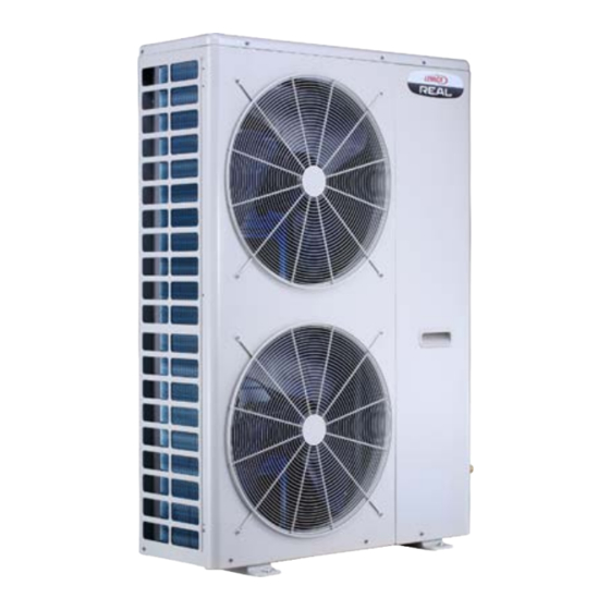
LENNOX REAL Heat Pump
VPC***H4-3P
VRF SYSTEMS
OUTDOOR UNITS
508369-01
06/2023
To ensure proper system performance and reliability,
Lennox does not recommend operation of VRF systems
during any phase of construction. Construction debris,
low temperatures, harmful vapors, and operation of the
unit with misplaced filters can damage the units. Failure
to follow these guidelines will result in the warranty be-
ing voided.
As with any mechanical equipment, contact with sharp
sheet metal edges can result in personal injury. Take
care while handling this equipment and wear gloves and
protective clothing.
IMPORTANT
The Clean Air Act of 1990 bans the intentional venting
of refrigerant (CFC's and HCFC's) as of July 1, 1992.
Approved methods of recovery, recycling or reclaiming
must be followed. Fines and/or incarceration may be
levied for non-compliance.
G ene ral
The Lennox REAL heat pump outdoor units are
matched with up to nine indoor units to create a VRF
(variable refrigerant flow) system that uses R-410A
refrigerant.
Refer to the Product Specification bulletin (EHB) for
the proper use of these heat pumps with matching
indoor units, header pipes, branch pipes, line sets
and controls.
These instructions are intended as a general guide
and do not supersede local or national codes in any
way. Authorities having jurisdiction should be con-
sulted before installation.
S hipping and P ac k ing Lis t
Check the components for shipping damage. If you
find any damage, immediately contact the last car-
rier. Package 1 of 1 contains the following:
1 - Assembled Lennox REAL heat pump outdoor
unit
1 - Outdoor unit installation instruction
1 - Warranty card
1 - Terminating resistor
1 - Magnet ring
1
CAUTION
CAUTION
Advertisement

Related Manuals for Lennox REAL VPC H4-3P Series


Summary of Contents for Lennox REAL VPC H4-3P Series
- Page 1 06/2023 CAUTION To ensure proper system performance and reliability, Lennox does not recommend operation of VRF systems during any phase of construction. Construction debris, low temperatures, harmful vapors, and operation of the unit with misplaced filters can damage the units. Failure to follow these guidelines will result in the warranty be- ing voided.
- Page 2 060 = 5 tons NOTE - Lennox REAL/VRF and Lennox Mini-Split products are similar in appearance to each other. Refer to the unit’s model number to determine if the unit is a REAL/VRF (V) or Mini-Split (M) unit. It is not possible to mix the two types of equipment on any system.
-
Page 3: Top View
V P C01 8H4 M- 3 P | VP C 0 2 4 H 4 M - 3 P | V P C 0 3 6 H 4 M - 3 P S Di m ensi ons CORNER WEIGHTS CENTER OF GRAVITY lbs. - Page 4 VPC03 6H 4M-3P D | V P C0 48H 4M-3 | V PC 060H 4 M- 3 P D im ens ion s CORNER WEIGHTS CENTER OF GRAVITY lbs. lbs. lbs. lbs. 5-3/8 15-3/4 (330 ) (400) Center of 14-1/8 Gravity (359) 23-5/8 (600)
-
Page 5: Single Unit Installation
NOTE - If unit is surrounded on three or four sides by walls or partitions that are taller than 10 ft. (3 m), call Lennox Commercial Applications group to discuss additional requirements. NOTE - 24 in. (610 mm) clearance required on top of unit. - Page 6 U nit Pl ace ment IMPORTANT WARNING Exhaust vents from dryers, water heaters and furnaces should be directed away from the Use the provided and specified components when outdoor unit. Prolonged exposure to exhaust installing equipment. Failure to do so may result in gases and the chemicals contained within them unit falling, water leaking or electrical shocks, caus- may cause condensation to form on the steel...
- Page 7 Condensate Drains Securing Outdoor Unit to Slab or Frame Brackets are provided at the base of the outdoor • The bottom of the outdoor unit is equipped with • unit so that it can be secured to a field-provided multiple drain holes to route water away from the unit during a defrost cycle.
- Page 8 Co ld Cl im ate Co n s id er at io ns Protective canopy Protective CAUTION canopy When operating the heat pump in a low outdoor ambient temperature, be sure to follow the instructions described below. - To prevent exposure to wind, install the outdoor unit with its coil air inlet side facing the wall.
- Page 9 Prevailing Winds Protection If unit coil cannot be installed away from prevailing winter winds, some method of protecting the coil is required. Minimum clearances from wind barrier must be observed at all times. Common 12 in application examples are: 305 mm Air Inlet •...
- Page 10 Buried Refrigerant Pipe Protection • All refrigerant lines must be insulated regardless of if it is buried. In addition to insulating each line of piping, • buried lines must rest inside a sealed, watertight conduit. • The conduit must be designed so it cannot collect and retain water.
- Page 11 I ns t all i ng the Un i t In si de of Bu il din g • Allow enough space between the unit and exte- REAL outdoor units may be installed indoors if the rior wall to allow for coil service. following guidelines are followed.
- Page 12 Exterior Wall (610) Clearance Unit Rear Discharge Air Opening Supply air inlet requirements 1721 in² (1.1 m) or 4100 cfm (1935 L/s) (914) (1397) Minimum Before (Service Adjacent Clearance) Obstructions NOTES - Louver angle should not exceed 15°. 24 in. (610 mm) clearance required on top of unit. Makeup air requirements are equal to or greater than discharge air volume.
- Page 13 Exterior Wall Field-Supplied Duct Unit Field-supplied foam Rear insulating tape NOTES- Louver angle should not exceed 15°. Inspection Door 24 in. (610 mm) clearance required on top of unit. within 12 inches Makeup air requirements are equal to or greater than discharge air (305 mm) of unit volume.
- Page 14 R e f r iger an t Pi p i n g Co nn ecti on s WARNING Refrigerant leaks are unlikely; however, if a refrigerant leak occurs, open a door or windows to dilute the refrigerant in the room. Turn off the unit and all other appliances that may cause a spark.
- Page 15 When multiple indoor units are served by a single The header kits can be used to connect a maximum outdoor unit, the refrigerant piping must be connect- of four indoor units to the outdoor unit. When the sys- tem includes five, six, seven, or eight indoor units, ed using either individual branch pipes or four-port header kits.
- Page 16 NOTE - Always slide a flare nut onto the field- IMPORTANT provided refrigerant piping before flaring the lines. Always use two wrenches when tightening flare 1. The seal on the unit refrigerant piping connections nuts to avoid twisting refrigerant piping. DO should remain in place until the last possible NOT over-tighten flare nuts.
- Page 17 Maximum Permitted Refrigerant Pipe Length and Maximum Height Difference - With Branch Pipe NOTE - See Refrigerant Pipe Selection Table to size Main Outdoor Pipe. Outdoor Description Designation Unit Main Outdoor Pipe - from outdoor unit to first branch pipe L3, L4, L5, L6 Main Indoor Pipe - from branch pipe to branch pipe L2, A, B, C, D, E...
- Page 18 NOTE - Header pipe kits should be placed between the Outdoor Unit and Indoor Units. Unit Header pipe kits cannot be connected in series. NOTE - In applications requiring more than one Header pipe kit, call Lennox VRF Applications Department for assistance. Header Pipe Kit V8HDRK04 Indoor unit...
- Page 19 NOTE - Header pipe kits should be placed between the Outdoor Unit and Indoor Units. Unit Header pipe kits cannot be connected in series. NOTE - In applications requiring more than one Header pipe kit, call Lennox VRF Applications Department for assistance. Header Pipe Kit V8HDRK04 Header Pipe Kit...
- Page 20 NOTE - Header pipe kits should be placed between the Outdoor Unit and Indoor Units. Header pipe kits cannot be connected in series. NOTE - In applications requiring more than one Header pipe kit, call Lennox VRF Applications Department for assistance. Outdoor Unit...
- Page 21 Maximum Permitted Refrigerant Pipe Length and Maximum Height Difference – With Non-VRF Air Handler or Coil/Furance NOTE - See Refrigerant Pipe Selection Table to size Main Outdoor Pipe. Description Designation Main Outdoor Pipe - from outdoor unit to indoor unit Outdoor Unit Non-VRF...
- Page 22 Refrigerant Pipe Selection Table 4. Main Outdoor Piping Sizes for Connection to VRF Indoor Units and AHU Control Kits MAIN OUTDOOR UNIT PIPE (L1) DIAMETER AND PIPE LENGTH BASED ON TOTAL CAPACITY Main Gas Main Maximum (Vapor) Pipe Liquid Pipe Indoor Unit Model No.
-
Page 23: Retrofit Installations
Table 6. Main Outdoor Piping Sizes for One-to-One Connection to Non-VRF Air Handler of Furnace Retrofit Installations ALLOWABLE LINE SET DIAMETER FROM EXISTING SYSTEM WITH NON-VRF AIR HANDLER OR COIL/FURNACE Outdoor Unit Existing Line Sets Gas Pipe Liquid Pipe Model No. Existing Line Set Existing Line Set Gas Pipe... - Page 24 Table 8. Indoor Piping Sizes for Connection to VRF Indoor Units and AHU Control Kits INDOOR PIPE SELECTION (L2, A, B, C, D, E, F, G, H) Indoor Unit Type Indoor Unit Size Gas (Vapor) Pipe Diameter Liquid Pipe Diameter V22B Compact 360°...
- Page 25 • The seal on the unit refrigerant piping connec- IMPORTANT tions should remain in place until the last pos- Use only oxygen-free nitrogen (OFN). sible moment. This will prevent dust or water from getting into the refrigerant piping before it Table 10.
- Page 26 A ddi t ional Refr ig e r a nt Ch ar g e using Table 11 below. When refrigerant piping connections have been completed, it will be necessary to adjust the system 2. Calculate the additional refrigerant charge for each liquid line branch pipe kit.
- Page 27 W iri ng Conn ecti o ns WARNING CAUTION Isolate the power supply before accessing unit electrical This unit must be properly grounded and protected by a terminals. circuit breaker. The ground wire for the unit must not be connected to a gas or water pipe, a lightning conductor Install unit so that unit disconnect is accessible.
- Page 28 CN19 CN17 FAN-UP FAN-DOWN FAN-DOWN FAN-UP H-PRO COMP. BLACK Inverter module Board HEATA L-OUT N-OUT HEAT-base SW1SW2 SW3SW4 DSP1 DSP2 ENC1 EEVA AC Fitter Board EEVC CN502 CN22 T7C1 N-IN CN501 L-IN CN18 CN14 CN15 BLACK RED CN3 CN2 X Y E P Q E M1 M2 C B Y L1 L2 ENC1 function definition:...
- Page 29 VRF Indoor Unit AHU Control Kit Air Handler/Furnace REAL Outdoor Unit Power Supply Power Supply Power Supply Power Supply (208/230V 1PH 60Hz) (90-250V 1PH 60 Hz) (Depends on Unit) (208/230V 1PH 60Hz) Incoming Incoming Incoming Incoming Electrical Electrical Electrical Electrical Supply Supply Supply...
- Page 30 Outdoor Unit Refrigerant Piping (PQ) Coil Control Kit Indoor Unit Indoor Unit Indoor Unit Install a terminating resistor (Ω120) on terminals P&Q on the indoor unit which is furthest from the outdoor unit. All Drain Wires will connect from outdoor unit chassis to indoor unit chassis at the end of the signal run.
- Page 31 Outdoor Refrigerant Piping Unit (PQ) Header Pipe Kit Header Pipe Kit V8HDRK04 V8HDRK04 Refrigerant Piping Coil Indoor Unit Indoor Unit Indoor Unit Indoor Unit Indoor Unit Indoor Unit Control Kit Install a terminating resistor (Ω120) on terminals P&Q on the indoor unit which is furthest from the outdoor unit.
-
Page 32: Outdoor Unit
Support 3H and 2C thermostat H/DH TH E RM O S TAT Note: Any time the electric heat elements are active, the indoor fan will run in high stage. INDOOR UNIT OUTDOOR UNIT Figure 31. Typical Communication Wiring Non-VRF Air Handler & 3H/2C Thermostat Wiring for 4H and 2C thermostat H/DH THERMOSTAT... - Page 33 Wiring for 3H and 1C thermostat H/DH T H E R M O S T A T Note: Because Y1 and Y2 are jumped, the indoor fan will only run in high stage. INDOOR UNIT OUTDOOR UNIT Note: Any time the electric heat elements are active, the indoor fan will run in high stage.
- Page 34 Wiring for 1H and 1C thermostat H/DH THERMOSTAT Note: Because Y1 and Y2 are jumped, the indoor fan will only run in high stage. INDOOR UNIT OUTDOOR UNIT Figure 31. Typical Communication Wiring Non-VRF Air Handler & 1H/1C Thermostat Wiring for 2H and 1C thermostat H/DH THERMOSTAT Note: Because Y1 and Y2 are...
- Page 35 Table 14. Electrical Parameters Model No. VPC018H4M-3P VPC024H4M-3P VPC036H4M-3PS Line voltage data - 60 Hz - 1 phase 208/230V 208/230V 208/230V Maximum Overcurrent Protection (MOCP) amps Minimum circuit ampacity (MCA) Compressor No. of compressors 14.6 Rated load amps 10.6 10.6 Outdoor Fan Motor type Motor...
- Page 36 C ommi ssi oni ng Checklist Before Start Up Commissioning Step 1: Power on All interconnecting pipework has been fully completed. Power on all indoor units and the outdoor unit. Condensate disposal system fully completed and gravity portions have been tested. Step 2: Enter commissioning mode Control cabling installation complete except for When the outdoor unit is first powered on, it displays...
- Page 37 The system is powered on Outdoor Unit Display and display “-.-.-.-.” Long press DOWN and UP buttons simultaneously for 5 seconds on the outdoor unit to enter the commissioning mode Short press Set the type of indoor units. the MENU Displays 01-0 which means button to the indoor unit type is VRF...
- Page 38 The system is automatically AU Ad represents addressed. Display AU Ad auto addressing and 0 0 in rotation. Takes 5-10 minutes and automatically proceeds to the next step. The system is initialized. Display INIt and 0 0 in INIt represents rotation.
- Page 39 Spo t C heck ( Di a g no st ic Da ta ) S W 2 Press SW 3 UP & SW 2 DOWN to CHECK the number of times shown in the No** column to view system data and performance information. No**.
- Page 40 No**. Parameter description Parameter value* 34 Reserved 35 High pressure of unit Actual pressure DISP. /100Unit: MPa 36 Low pressure of unit Actual pressure DISP. /100Unit: MPa 37 Quantity of online indoor units Actual quantity 38 Quantity of running indoor units Actual quantity [0] OFF [1] C1: Condenser...
- Page 41 Troubl esh oot in g Error Code Definition Digital Display Communication error between indoor and main outdoor unit T3/T4/T5/TL/T71/T8 temperature sensor error Power voltage out of range Compressor discharge temp sensor error EEPROM error EEVA/EEVC error Inverter Module Temperature Protection High Pressure Protection Input current over load High compressor discharge temperature protection...
- Page 42 Service & S etu p F un ctio ns Table 15. Digital Display Output Parameters Parameters Outdoor Unit Displayed on Displayed on State DSP1 DSP2 Standby The number of indoor units in Unit’s Address communication with the outdoor unit Normal Running Operation Speed of the...
- Page 43 Menu Mode Start 1. Press and hold SW1 (MENU) for 5 seconds to enter menu mode. The digital display will display Long press Press MENU “n1. MENU 5 2. Press SW2 / SW3 (DOWN / UP) button to select seconds the first-level menu “n1”, “n2”, “n3”, “n4”, or “nb”.
- Page 44 Table 17. Function Menu First- Specified Second- Level Description Default Level Menu Menu Mode Menu Error Code History Clear Error Code History Indoor Unit Address Driver’s Address Service Mode Cooling Test Heating Test Refrigerant Recovery to Outdoor Unit [1]* Refrigerant Recovery to Indoor Unit Balance System Refrigerant Vacuum Mode Set VIP Indoor Unit Address...
- Page 45 First- Specified Second- Level Description Default Level Menu Menu Mode Menu Network Address [2]* Number of Indoor Units Auto Address [4]* Clear Address VRF Indoor Unit or AHU Control Kit (PQ Communica- tion) Non-VRF Indoor Unit (CBYW (24V) Communication) 4-Way Valve Controlled by B Non-VRF Indoor Unit (CBYW (24V) Communication) 4-Way Valve Controlled by O T2B Target temperature setting (Ke0=27)
- Page 46 First- Specified Second- Level Description Default Level Menu Menu Mode Menu No compressor lockout temperature 7°F (-14°C) compressor lockout temperature 10°F (-12°C) compressor lockout temperature 16°F (-9°C) compressor lockout temperature 19°F (-7°C) compressor lockout temperature 25°F (-4°C) compressor lockout temperature 30°F (-1°C) compressor lockout temperature 36°F (2°C) compressor lockout temperature [8]*...
- Page 47 Auto Cha r ge Turn ON the indoor unit in the CAUTION COOLING mode Only use auto charge if all of the following conditions are met or damage to the equipment may occur. The system is in COOLING 1. Refrigerant pipe length is unknown. mode and LED displays 0 1 2.
- Page 48 Figure 34. Single Fan Cabinet Auto Charge Port Figure 35. Dual Fan Cabinet Auto Charge Port...
- Page 52 Technical Support 1-800-4LENNOX (1-800-453-6669) vrftechsupport@lennoxind.com www.LennoxCommercial.com Scan this QR code to download the Lennox VRF & Mini-Splits App from the Apple App Store or the Google Play store. The app contains technical literature and troubleshooting resources.
Need help?
Do you have a question about the REAL VPC H4-3P Series and is the answer not in the manual?
Questions and answers