Table of Contents
Advertisement
©2019 Lennox Industries Inc. Dallas, Texas, USA
THIS MANUAL MUST BE LEFT WITH THE
OWNER FOR FUTURE REFERENCE
These instructions are intended as a general guide and do
not supersede local codes in any way. Consult authorities
having jurisdiction before installation.
WARNING
Improper installation, adjustment, alteration, ser-
vice or maintenance can cause property damage,
personal injury or loss of life.
Installation and service must be performed by a li-
censed professional HVAC installer, service agency
or the gas supplier.
Failure to follow safety warnings and these instruc-
tions exactly could result in property damage, dan-
gerous operation, serious injury, or death.
Any additions, changes, or conversions required in
order for the appliance to satisfactorily meet the ap-
plication needs must be made by a licensed profes-
sional HVAC installer (or equivalent) using factory-
specified parts.
Do not use this system if any part has been under
water. A flood-damaged appliance is extremely dan-
gerous. Immediately call a licensed professional
HVAC service technician (or equivalent) to inspect
the system and to replace all controls and electrical
parts that have been wet, or to replace the system, if
deemed necessary.
VRF
1
INSTALLATION/OPERATION
INSTRUCTIONS
Mini-VRF Heat Pump
VPB***H4-3P
VRF SYSTEMS
OUTDOOR UNITS
507998-01
10/2019
CAUTION
To ensure proper system performance and reliability,
Lennox does not recommend operation of VRF sys-
tems during any phase of construction. Construction
debris, low temperatures, harmful vapors, and opera-
tion of the unit with misplaced filters can damage the
units. Failure to follow these guidelines will result in the
warranty being voided.
CAUTION
As with any mechanical equipment, contact with sharp
sheet metal edges can result in personal injury. Take
care while handling this equipment and wear gloves and
protective clothing.
IMPORTANT
The Clean Air Act of 1990 bans the intentional venting
of refrigerant (CFC's and HCFC's) as of July 1, 1992.
Approved methods of recovery, recycling or reclaiming
must be followed. Fines and/or incarceration may be
levied for non-compliance.
General
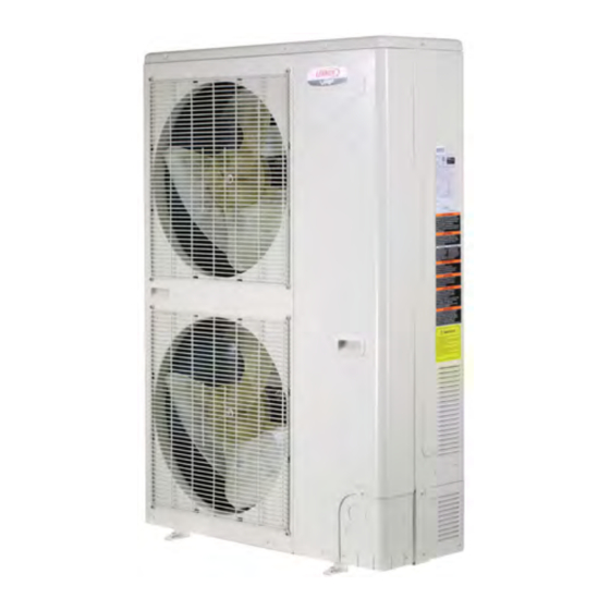
The Mini-VRF heat pump outdoor units are matched
with up to nine indoor units to create a VRF (variable
refrigerant flow) system that uses R-410A refrigerant.
Refer to the Product Specification bulletin (EHB) for
the proper use of these heat pumps with matching
indoor units, header pipes, branch pipes, line sets
and controls.
These instructions are intended as a general guide
and do not supersede local or national codes in any
way. Authorities having jurisdiction should be con-
sulted before installation.
Shipping and Packing List
Check the components for shipping damage. If you
find any damage, immediately contact the last car-
rier. Package 1 of 1 contains the following:
1 - Assembled Mini-VRF heat pump outdoor unit
1 - Outdoor unit installation instruction
Advertisement
Table of Contents

Related Manuals for Lennox VPB H4-3P Series


Summary of Contents for Lennox VPB H4-3P Series
- Page 1 10/2019 CAUTION To ensure proper system performance and reliability, Lennox does not recommend operation of VRF sys- tems during any phase of construction. Construction debris, low temperatures, harmful vapors, and opera- tion of the unit with misplaced filters can damage the units.
-
Page 2: Model Number Identification
H = High Efficiency NOTE - Lennox VRF and Lennox Mini-Split products are similar in appearance to each other. Refer to the unit’s model number to determine if the unit is a VRF (V) or Mini-Split (M) unit. It is not possible to mix the two types of equipment on any system. -
Page 3: Center Of Gravity
Dimensions - Inches (mm) CORNER WEIGHTS CENTER OF GRAVITY Model No. lbs. lbs. lbs. lbs. 7-3/8 All Models 21-5/8 23-5/8 (600) (152) (19) CENTER OF 13-3/4 14-1/4 12-5/8 15-3/4 GRAVITY (349) (362) (321) (400) TOP VIEW 52-1/4 (1327) 35-3/8 (899) FRONT VIEW... -
Page 4: Single Unit Installation
NOTE - If unit is surrounded on three or four sides by walls or partitions that are taller than 10 ft. (3 m), call Lennox VRF Applications group to discuss additional requirements. NOTE - 24 in. (610 mm) clearance required on top of unit. - Page 5 Unit Placement IMPORTANT WARNING Exhaust vents from dryers, water heaters and furnaces should be directed away from the Use the provided and specified components when outdoor unit. Prolonged exposure to exhaust installing equipment. Failure to do so may result in gases and the chemicals contained within them unit falling, water leaking or electrical shocks, caus- may cause condensation to form on the steel...
-
Page 6: Bottom View
Condensate Drains Securing Outdoor Unit to Slab or Frame Brackets are provided at the base of the outdoor • The bottom of the outdoor unit is equipped with • unit so that it can be secured to a field-provided multiple drain holes to route water away from the unit during a defrost cycle. - Page 7 Cold Climate Considerations Protective canopy Protective CAUTION canopy When operating the heat pump in a low outdoor ambient temperature, be sure to follow the instructions described below. - To prevent exposure to wind, install the outdoor unit 24 in 610 mm with its suction side facing the wall.
- Page 8 Prevailing Winds Protection If unit coil cannot be installed away from prevailing winter winds, some method of protecting the coil is required. Minimum clearances from wind 12 in barrier must be observed at all times. Common 305 mm application examples are: Air Inlet Construct a wind barrier.
- Page 9 Buried Refrigerant Pipe Protection • All refrigerant lines must be insulated regardless of if it is buried. In addition to insulating each line of piping, • buried lines must rest inside a sealed, watertight conduit. • The conduit must be designed so it cannot collect and retain water.
- Page 10 Installing the Unit Inside of Building • Allow enough space between the unit and exte- Mini-VRF outdoor units may be installed indoors if the following guidelines are followed. rior wall to allow for coil service. • Provide a drain pan underneath the unit to pre- •...
- Page 11 Exterior Wall (610) Clearance Unit Rear Discharge Air Opening Supply air inlet requirements 1721.06 sq.in. CFM = 4100 (914) (1397) Minimum Before (Service Adjacent Clearance) Obstructions NOTES - Louver angle should not exceed 15°. 24 in. (610 mm) clearance required on top of unit. Makeup air requirements are equal to or greater than discharge air volume.
- Page 12 Exterior Wall Field-Supplied Duct Unit Field-supplied foam Rear insulating tape NOTES- Louver angle should not exceed 15°. Inspection Door 24 in. (610 mm) clearance required on top of unit. within 12 inches Makeup air requirements are equal to or greater than discharge air (305 mm) of unit volume.
- Page 13 Refrigerant Piping Connections REMOVE COVER PLATE TO FACILITATE PIPING. WARNING Refrigerant leaks are unlikely; however, if a refrigerant leak occurs, open a door or windows to dilute the refrigerant in the room. Turn off the unit and all other appliances that may cause a spark. Call a licensed professional HVAC technician (or UNIT FRONT UNIT SIDE...
- Page 14 When multiple indoor units are served by a single The header kits can be used to connect a maximum outdoor unit, the refrigerant piping must be connect- of four indoor units to the outdoor unit. When the sys- tem includes five, six, seven, or eight indoor units, ed using either individual branch pipes or four-port header kits.
- Page 15 NOTE - Always slide a flare nut onto the field- IMPORTANT provided refrigerant piping before flaring the lines. Always use two wrenches when tightening flare 1. The seal on the unit refrigerant piping connections nuts to avoid twisting refrigerant piping. DO should remain in place until the last possible NOT over-tighten flare nuts.
- Page 16 Maximum Permitted Refrigerant Pipe Length and Maximum Height Difference - With Branch Pipe NOTE - See Refrigerant Pipe Selection Table to size Main Outdoor Pipe. Description Designation Mini-VRF Heat Pump Main Outdoor Pipe - from outdoor unit to first branch pipe Outdoor unit L3, L4, L5, L6 Main Indoor Pipe - from branch pipe to branch pipe...
- Page 17 Heat Pump Header pipe kits cannot be connected in series. Outdoor unit NOTE - In applications requiring more than one Header pipe kit, call Lennox VRF Applications Department for assistance. Header Pipe Kit V8HDRK04 Indoor unit Length and Maximum Height Difference...
- Page 18 Mini-VRF Header pipe kits cannot be connected in series. Heat Pump Outdoor unit NOTE - In applications requiring more than one Header pipe kit, call Lennox VRF Applications Department for assistance. Header Pipe Kit V8HDRK04 Header Pipe Kit V8HDRK04 Indoor unit...
- Page 19 NOTE - Header pipe kits should be placed between the Outdoor Unit and Indoor Units. Header pipe kits cannot be connected in series. NOTE - In applications requiring more than one Header pipe kit, Mini-VRF call Lennox VRF Applications Department for assistance. Heat Pump Outdoor unit Header Pipe Kit...
- Page 20 Refrigerant Pipe Selection MAIN OUTDOOR UNIT PIPE (L1) DIAMETER AND PIPE LENGTH BASED ON TOTAL CAPACITY Main Main Maximum Gas Pipe Liquid Pipe Indoor Unit Model No. Capacity Liquid Pipe Length Number of Diameter Diameter Branch Pipe Indoor Units Required Required Less than 148 ft.
- Page 21 INDOOR PIPE SELECTION (L2, A, B, C, D, E, F, G, H) Indoor Unit Type Indoor Unit Size Gas Pipe Diameter Liquid Pipe Diameter 007, 009, 012, 015 1/4 in. V22B Compact 360° Cassette 1/2 in. 009, 012, 015 1/4 in. 1/2 in.
- Page 22 8000 Microns (8 Torr) psig and hold for 1 hour. Evacuate System using all service valves. Follow the Lennox pressure test specifications • 2. Break the vacuum by allowing nitrogen into the in table 1 and the triple evacuation process de-...
- Page 23 Additional Refrigerant Charge When refrigerant piping connections have been 1. Calculate the additional refrigerant charge using completed, it will be necessary to adjust the system the diameter and length of the liquid pipe (only) using Table 4 below. refrigerant charge based on the diameter and length of the liquid line pipe between the outdoor and indoor 2.
-
Page 24: Wiring Connections
Wiring Connections WARNING CAUTION Isolate the power supply before accessing unit electrical This unit must be properly grounded and protected terminals. by a circuit breaker. The ground wire for the unit must not be connected to a gas or water pipe, a lightning Install unit so that unit disconnect is accessible. -
Page 25: Compressor Module
BOTTOM-FAN Part Name WIRING DIAGRAM(OUTDOOR UNIT) Code Part Name Code TOP-FAN Compressor Rectifier COMP CAP1 Capacitor Pfc inductor CAP2 Resistor Ac curren sensor 4-way valve Magnetic ring CH1-CH9 STF1 TRANS IN THANS OUT CN19 CN17 Electronic expansion Solenoid valve SV4-SV6 BLUE CN26 CN51... - Page 26 Power(208/230V 1PH 60Hz) Incoming Electrical Supply Incoming Electrical Supply Outdoor Unit Control Indoor Indoor Indoor Indoor Unit Unit Unit Unit J- Box J- Box J- Box J- Box J- Box Power wire between indoor units Figure 25. Typical 208/230V Power Wiring Outdoor Unit Local Local...
- Page 27 Outdoor Unit Refrigerant Piping (PQ) Coil Indoor Unit Indoor Unit Indoor Unit Control Kit Install a terminating resistor (Ω120) on terminals P&Q on the indoor unit which is furthest from the outdoor unit. All Drain Wires will connect from outdoor unit chassis to mode selection box chassis at the end of the signal run.
- Page 28 Outdoor Unit Refrigerant Piping (PQ) Header Pipe Kit Header Pipe Kit V8HDRK04 V8HDRK04 Refrigerant Piping Coil Indoor Unit Indoor Unit Indoor Unit Indoor Unit Indoor Unit Indoor Unit Control Kit Install a terminating resistor (Ω120) on terminals P&Q on the indoor unit which is furthest from the outdoor unit.
- Page 29 Outdoor Unit Main Control Board SW2 SW1 Display ENC2 SW4 SW3 Figure 31. Typical Outdoor Unit Main Board...
- Page 30 Network Address and Commissioning SW3 Priority Configuration After the system has been installed, the outdoor unit will automatically assign addresses to all connected Outdoor Ambient. Determine mode priority indoor units. These addresses may be modified based on outdoor temperature. 1 2 3 using an optional remote control as part of the commissioning procedure.
- Page 31 Spot Check (Diagnostic Data) SW 2 Press SW 2 CHECK the number of times shown in the No** column to view system data and performance information. No**. Parameter description Parameter value* If all indoor units off, it will show the quantity of all indoor units; if the outdoor unit is in time delay, it will show 0;...
- Page 32 Service & Setup Functions Forced cooling and manual defrost are service functions that can be performed from the outdoor unit. Forced Cooling Press and hold SW 1 FORCE_COOL and hold for 5 seconds. Forced Cooling will override and disable all controllers restricting end-user(s) operation, this is to include •...
- Page 33 Access Service Menu Press SW 2 CHECK and hold for 5 seconds. Press SW 1 FORCE_COOL to cycle through the Level 1 menu items. Press SW 2 CHECK to select the current Level 1 menu item. Press SW 1 FORCE_COOL to cycle through the Level 2 menu items. Press SW 2 CHECK to select the current Level 2 menu item and return to the Level 1 menu.
- Page 34 Cancel LVM Emergency Stop An emergency stop command can be sent from the LVM centralized controller to the outdoor unit. Select 1 to cancel the emergency stop command. The outdoor unit will display 0A0 during forced stop. Test Operation The system can be forced into cooling or heating mode for performance testing. Select 1 for forced cooling test and select 2 for forced heating test.
- Page 36 Technical Support 1-844-GET-VRF1 (1-844-438-8731) vrftechsupport@lennoxind.com www.LennoxVRF.com Download the app from the Apple App Store or the Google Play store.
Need help?
Do you have a question about the VPB H4-3P Series and is the answer not in the manual?
Questions and answers