Table of Contents
Advertisement
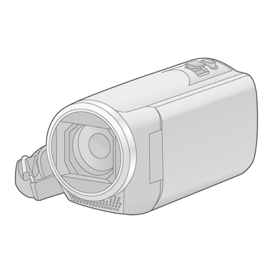
High Definition Video Camera
HC-V180PP
Model No.
HC-V180PU
HC-V180PR
HC-V180EB
HC-V180EC
HC-V180EF
HC-V180EG
HC-V180EP
HC-V180GA
HC-V180GC
HC-V180GK
HC-V180GN
HC-V180GW
Colour
(K)...........Black Type
© Panasonic Corporation 2016 Unauthorized copy-
ing and distribution is a violation of law.
ORDER NO.VM1601001CE
B27
Advertisement
Table of Contents


Need help?
Do you have a question about the HC-V180PP and is the answer not in the manual?
Questions and answers