Table of Contents
Advertisement
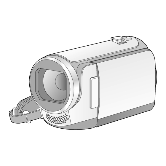
High Definition Video Camera
HC-V100P
Model No.
HC-V100PC
HC-V100PU
HC-V100EB
HC-V100EC
HC-V100EE
HC-V100EF
HC-V100EG
HC-V100EP
HC-V100GC
HC-V100GK
HC-V100GN
HC-V100GW
HC-V100MP
HC-V100MPC
HC-V100MPU
HC-V100MGK
Colour
[ HC-V100 ]
(K)...........Black Type
(W)..........White Type (only EB/EC/EE/EG/EP/GK)
[ HC-V100M ]
(K)...........Black Type
© Panasonic Corporation 2012 Unauthorized copy-
ing and distribution is a violation of law.
ORDER NO. VM1202003CE
B27
Advertisement
Table of Contents

Related Manuals for Panasonic HC-V100P


Summary of Contents for Panasonic HC-V100P
- Page 1 HC-V100EF HC-V100EG HC-V100EP HC-V100GC HC-V100GK HC-V100GN HC-V100GW HC-V100MP HC-V100MPC HC-V100MPU HC-V100MGK Colour [ HC-V100 ] (K)...Black Type (W)..White Type (only EB/EC/EE/EG/EP/GK) [ HC-V100M ] (K)...Black Type © Panasonic Corporation 2012 Unauthorized copy- ing and distribution is a violation of law.
-
Page 2: Table Of Contents
TABLE OF CONTENTS PAGE PAGE 1 Safety Precautions -----------------------------------------------3 1.1. General Guidelines ----------------------------------------3 1.2. Leakage Current Cold Check ---------------------------3 1.3. Leakage Current Hot Check (See Figure 1.)--------3 2 Warning --------------------------------------------------------------4 2.1. Prevention of Electrostatic Discharge (ESD) to Electrostatically Sensitive (ES) Devices ----------4 2.2. -
Page 3: Safety Precautions
1 Safety Precautions 1.1. General Guidelines 1.3. Leakage Current Hot Check (See Figure 1.) 1. IMPORTANT SAFETY NOTICE There are special components used in this equipment 1. Plug the AC cord directly into the AC outlet. Do not use which are important for safety. These parts are marked by an isolation transformer for this check. -
Page 4: Warning
2 Warning 2.1. Prevention of Electrostatic Discharge (ESD) to Electrostatically Sensitive (ES) Devices Some semiconductor (solid state) devices can be damaged easily by static electricity. Such components commonly are called Elec- trostatically Sensitive (ES) Devices. Examples of typical ES devices are integrated circuits and some field-effect transistors and semiconductor "chip"... -
Page 5: Caution For Ac Cord (For Eb
2.3.2.3. How to Replace the Fuse A replacement fuse cover can be purchased from your local Panasonic Dealer. 1. Remove the Fuse Cover with a screwdriver. If the fitted moulded plug is unsuitable for the socket outlet in your home then the fuse should be removed and the plug cut off and disposed of safety. -
Page 6: How To Replace The Lithium Battery
NOTE: This Lithium battery is a critical component. (Type No.: ML-614S/DN Manufactured by Energy Company, Panasonic Corporation) It must never be subjected to excessive heat or discharge. It must therefore only be fitted in requirement designed specifically for its use. -
Page 7: Service Navigation
When a part replacement is required for repairing MAIN P.C.B., replace as an assembled parts. (Main P.C.B.) 2. The following category is /are recycle module part. Please send it/them to Central Repair Center. • MAIN P.C.B. (VEP03J56CN: HC-V100P/PC/PU) • MAIN P.C.B. (VEP03J56CP: HC-V100EB/EC/EE/EF/EG/EP/GC/GK/GN/GW) •... -
Page 8: How To Define The Model Suffix (Ntsc Or Pal Model)
3.4. How to Define the Model Suffix (NTSC or PAL model) There are seven kinds of HC-V100/V100M. • a) HC-V100M (Japan domestic model) • b) HC-V100P, V100MP • c) HC-V100PC, V100MPC • d) HC-V100EB/EC/EF/EG/EP/GN • e) HC-V100EE • f) HC-V100GK, V100MGK •... -
Page 9: Formatting
3.5. Formatting... -
Page 10: Specifications
4 Specifications... -
Page 12: Location Of Controls And Components
5 Location of Controls and Components Speaker USB terminal [ ] Intelligent auto/Manual button [iA/MANUAL] Optical image stabilizer/Delete button O.I.S./ Power button [ HDMI mini connector [HDMI] AV multi connector [AV MULTI] Use the AV multi cable (only the supplied AV MULTI cable). - Page 13 21 Tripod receptacle If you attach a tripod which has a 5.5 mm (0.22 ) screw or larger, it may damage this unit. 22 SD card cover 23 Access lamp [ACCESS] 24 Card slot 25 Photoshot button [ 26 Zoom lever [W/T] (In Recording Mode) Thumbnail display switch [ Volume lever [ VOL ] (In Playback...
-
Page 14: Service Mode
6 Service Mode 1. Indication method of the service menu Set the mode switch “Recording” mode. 2. Turn the power on, and then while keep pressing the “Zoom lever” to W side, “Intelligent auto/Manual” button and “Menu” but- ton for more than 3 seconds until the top screen of the Service Mode Menu being displayed. Lock search history indication •... -
Page 15: History Display
6.1. History Display Press the “[UP] or [DOWN] of cursor” button for the item No. [4] is yellow high lighted, then press “ENTER” button to display the unit histories. Operation specifications Indication contents • Display the total operating time (in power on and EE state), total movie recording time and total number of photo taken. (They are stored in EEPROM). -
Page 16: Service Fixture & Tools
7 Service Fixture & Tools 7.1. When Replacing the Main P.C.B. After replacing the MAIN P.C.B., be sure to achieve adjustment. The adjustment instruction is available at “software download” on the “Support Information from NWBG/VDBG-AVC” web-site in “TSN system”, together with Maintenance software. 7.2. -
Page 17: Disassembly And Assembly Instructions
8 Disassembly and Assembly Instructions 8.1. Disassembly Flow Chart for the 8.3. Disassembly Procedure for the Unit Unit This is a disassembling chart. When assembling, perform this chart conversely. Item Removal Top Case Unit Fig. D1 1 Screw (A) Fig. D2 2 Screws (B) 3 Locking tabs 3 Hooking parts... - Page 18 8.3.1. Removal of the Top Case Unit Fig. D2 Fig. D1...
- Page 19 8.3.2. Removal of the Side Case L Unit Fig. D4 8.3.3. Removal of the Front Case Unit Fig. D3 Fig. D5...
- Page 20 Fig. D6 8.3.4. Removal of the Lens Unit Fig. D8 Fig. D7...
- Page 21 8.3.5. Removal of the Main P.C.B. and SD Holder P.C.B. Fig. D10 Fig. D9...
- Page 22 8.3.7. Removal of the LCD Case T Unit and LCD Unit Fig. D11 8.3.6. Removal of the ESD P.C.B. Unit (HC-V100M only) Fig. D13 Fig. D12...
- Page 23 Fig. D14...
-
Page 24: Measurements And Adjustments
9 Measurements and Adjustments 9.1. Electric Adjustment • Adjustment method is different from a conventional High definition video camera. • An exclusive jig and PC (including software for adjustment “Tatsujin”) are necessary for electric adjustment. • A USB driver for service is necessary to communication with PC. •... - Page 25 Adjustment Items • Adjustment item as follows. The adjustment instruction is available at "Software download" on the "Support Information from NWBG/VDBG-AVC" web-site in "TSN System".
-
Page 26: Factory Setting
10 Factory Setting 10.1. How To Turn On The Factory Settings? (CAUTION) Performing the factory settings, the built-in memory is initialized and all of recorded data are deleted. (SD memory card is not initialized by the factory settings.) 1. Set the mode switch “Recording” mode. 2. -
Page 27: Block Diagram
10 Block Diagram 10.1. Overall Block Diagram OVERALL BLOCK DIAGRAM : VIDEO SIGNAL NOTE : AUDIO SIGNAL : CLK or CONTROL LINE LENS(F1.8 4.0 34x) COLOR LCD IC201 PANEL ZOOM/ MOS IMAGE FOCUS IRIS SENSOR MOTOR/ IC202,302 GATE IC IC3751 IC3701 Analog VIDEO... -
Page 28: Camera/System Control Circuit Block Diagram
10.2. Camera/System Control Circuit Block Diagram CAMERA/SYSTEM CONTROL CIRCUIT BLOCK DIAGRAM IC2006 IC2002 (SYSTEM CONTROL) (EEPROM) CL2008 CK2003 EEPROM CS IC3401 IC201 CL2011 CK2004 (ASIC) (MOS IMAGE SENSOR) EEPROM DO CL2009 CK2006 EEPROM DI CL2010 CK2007 RL3431 RL3432 EEPROM WP CL2013 CK2005 BUS240 DOAP... -
Page 29: Video/Audio Signal Process(1) Circuit Block Diagram
10.3. Video/Audio Signal Process(1) Circuit Block Diagram VIDEO/AUDIO SIGNAL PROCESS ( 1 ) CIRCUIT BLOCK DIAGRAM IC3402/3403 IC3404 (NAND FLASH ROM/512M-bit) (DDR3 SDRAM/1G-bit) IC3402 ONLY IC3403 ONLY CTL SIG CTL SIG CTL SIG ADDRESS CTL SIG DATA DATA DATA G3 F3 B7 C7 E7 D3 G3 F3 B7 C7 E7 D3... -
Page 30: Video/Audio Signal Process(2) Circuit Block Diagram
10.4. Video/Audio Signal Process(2) Circuit Block Diagram VIDEO/AUDIO SIGNAL PROCESS(2)CIRCUIT BLOCK DIAGRAM IC3401 (ASIC) G VOUT VBO L3 G LOUT LOUT H3 G ROUT ROUT J3 HD STNDBY GPIOA19 U25 S CLK VDAC GPIOB1 P21 S SDA VDAC GPIOB0 M19 PW 3.2V E AVIO RST GPIOA20 U24... -
Page 31: Lens Drive Circuit Block Diagram
10.5. Lens Drive Circuit Block Diagram LENS DRIVE CIRCUIT BLOCK DIAGRAM IC2006 (SYSTEM CONTROL) QR775 LED CONT ZENC FP6008 FENC ZLEDCONT ZABS LENS TEMP FLEDCONT FABS LENS TEMP IC701 IC3401 (LENS/OIS DRIVE) (ASIC) FOCUS ENC ZOOM ENC CH711 CLK27 LENS L CK27M MCLKO IC705... -
Page 32: Power Supply Circuit Block Diagram
10.6. Power Supply Circuit Block Diagram POWER SUPPLY CIRCUIT BLOCK DIAGRAM Please check the Fuse Resistor when an output JK6401 IP6401 voltage does not output. FUSE RESISTOR: DC IN (R1261/R6409) CL1001 Q1501 CL1341 PW DDR1.5V CL1002 PW SENS1.8V JK6701 CL1331 IP1502 CL1461 PW REG1.8V... -
Page 33: Wiring Connection Diagram
11 Wiring Connection Diagram 11.1. Interconnection Diagram INTERCONNECTION DIAGRAM BATTERY HC-V100M only BATTERY CATCHER P.C.B. (FOIL SIDE) ESD P.C.B. : (COMPONENT SIDE) (FOIL SIDE) TOP OPERATION P6701 BATT + BATT + SPEAKER BATT - BATT - FP6003 ECM FPC PP6001 SD CMD NOREG D GND... - Page 34 Model No. : HC-V100/V100M Schematic Diagram Note...
- Page 35 Model No. : HC-V100/V100M Parts List Note...
- Page 36 Model No. : HC-V100/V100M Main Connection (Main P.C.B.)
- Page 37 Model No. : HC-V100/V100M Video (Main P.C.B.)
- Page 38 Model No. : HC-V100/V100M HD Video (Main P.C.B.)
- Page 39 Model No. : HC-V100/V100M Lens Drive (Main P.C.B.)
- Page 40 Model No. : HC-V100/V100M Syscon (Main P.C.B.)
- Page 41 Model No. : HC-V100/V100M Charge/RTC (Main P.C.B.)
- Page 42 Model No. : HC-V100/V100M MIC (Main P.C.B.)
- Page 43 Model No. : HC-V100/V100M Power (Main P.C.B.)
- Page 44 Model No. : HC-V100/V100M MOS Connection (Main P.C.B.)
- Page 45 Model No. : HC-V100/V100M SD Holder (SD Holder P.C.B.)
- Page 46 Model No. : HC-V100/V100M Main P.C.B. (Component Side)
- Page 47 Model No. : HC-V100/V100M Main P.C.B. (Foil Side)
- Page 48 Model No. : HC-V100/V100M SD Holder P.C.B.(Component Side)
- Page 49 Model No. : HC-V100/V100M SD Holder P.C.B.(Foil Side)
- Page 50 Model No. : HC-V100/V100M Parts List Ref. Safety Part No. Part Name & Description Q'ty Remarks B6401 ML-614S/DN BUTTON BATTERY 1 [ENERGY] C302 F1L0J1040001 C.CAPACITOR CH 6.3V 0.1U C303 F1G0J1050007 C.CAPACITOR CH 6.3V 1U C304 F1G0J1050007 C.CAPACITOR CH 6.3V 1U C305 F1G1C104A077 C.CAPACITOR CH 16V 0.1U...
- Page 51 Model No. : HC-V100/V100M Parts List Ref. Safety Part No. Part Name & Description Q'ty Remarks C1520 F1G1C104A077 C.CAPACITOR CH 16V 0.1U C1521 F1L0J1040001 C.CAPACITOR CH 6.3V 0.1U C1522 F1L0J1040001 C.CAPACITOR CH 6.3V 0.1U C1523 F1L0J1040001 C.CAPACITOR CH 6.3V 0.1U C2002 F3F0J226A032 T.CAPACITOR CH 6.3V 22U...
- Page 52 Model No. : HC-V100/V100M Parts List Ref. Safety Part No. Part Name & Description Q'ty Remarks C3446 F1L0J1040001 C.CAPACITOR CH 6.3V 0.1U C3447 F1L0J1040001 C.CAPACITOR CH 6.3V 0.1U C3448 F1L0J1040001 C.CAPACITOR CH 6.3V 0.1U C3453 F1L0J1040001 C.CAPACITOR CH 6.3V 0.1U C3455 F1J0J106A049 C.CAPACITOR CH 6.3V 10U...
- Page 53 Model No. : HC-V100/V100M Parts List Ref. Safety Part No. Part Name & Description Q'ty Remarks C6020 F1G0J1050007 C.CAPACITOR CH 6.3V 1U C6021 F1G0J1050007 C.CAPACITOR CH 6.3V 1U C6022 F1L0J1040001 C.CAPACITOR CH 6.3V 0.1U C6023 F1G1H220A644 C.CAPACITOR CH 50V 22P C6401 F1J1A106A043 C.CAPACITOR CH 10V 10U...
- Page 54 Model No. : HC-V100/V100M Parts List Ref. Safety Part No. Part Name & Description Q'ty Remarks L1271 G1C6R8MA0478 CHIP INDUCTOR 6.8UH L1501 G1C4R7ZA0240 CHIP INDUCTOR 4.7UH L3402 G1C100MA0495 CHIP INDUCTOR 10UH L3403 G1C100MA0495 CHIP INDUCTOR 10UH L3404 G1C100MA0408 CHIP INDUCTOR 10UH L3603 G1C100KA0115 CHIP INDUCTOR 10UH...
- Page 55 Model No. : HC-V100/V100M Parts List Ref. Safety Part No. Part Name & Description Q'ty Remarks R719 D0GAR00J0005 RESISTOR R731 ERJ2RHD102X M.RESISTOR CH 1/16W 1K R734 ERJ2RHD122 M.RESISTOR CH 1/16W 1.2K R775 ERJ1GEJ221 M.RESISTOR CH 1/20W 220 R776 ERJ1GEJ473 M.RESISTOR CH 1/20W 47K R778 ERJ1GEJ473 M.RESISTOR CH 1/20W 47K...
- Page 56 Model No. : HC-V100/V100M Parts List Ref. Safety Part No. Part Name & Description Q'ty Remarks R2018 ERJ2RKD184 M.RESISTOR CH 1/16W 180K R2020 D0GA473JA023 RESISTOR R2304 ERJ1GEJ102 M.RESISTOR CH 1/20W 1K R2312 D0GA472JA023 RESISTOR R3406 ERJ1GEJ473 M.RESISTOR CH 1/20W 47K R3407 ERJ1GEJ473 M.RESISTOR CH 1/20W 47K...
- Page 57 Model No. : HC-V100/V100M Parts List Ref. Safety Part No. Part Name & Description Q'ty Remarks R3756 ERJ1GEJ102 M.RESISTOR CH 1/20W 1K R3757 ERJ1GEJ821 M.RESISTOR CH 1/20W 820 R3758 ERJ2RHD392X M.RESISTOR CH 1/16W 3.9K R3759 ERJ2RHD301 M.RESISTOR CH 1/16W 300 R3760 ERJ2RHD301 M.RESISTOR CH 1/16W 300...
- Page 58 Model No. : HC-V100/V100M Parts List Ref. Safety Part No. Part Name & Description Q'ty Remarks RX6002 D1H88204A024 RESISTOR NETWORKS RX6003 D1H86834A024 RESISTOR NETWORKS 1 MP,MPC,MPU,MGK S6001 ESE18L62BXFD SWITCH S6401 K0H1BA000580 SWITCH S6402 K0H1BA000580 SWITCH S6403 K0H1BA000580 SWITCH S6404 K0F111A00475 SWITCH VA301 D4ED16R80001...
- Page 59 Model No. : HC-V100/V100M Frame and Casing Section...
- Page 60 Model No. : HC-V100/V100M Packing Parts and Accessories Section...
- Page 61 Model No. : HC-V100/V100M Parts List Ref. Safety Part No. Part Name & Description Q'ty Remarks VYK5K44 TOP CASE UNIT 1 (-K) VYK5N56 TOP CASE UNIT 1 (-W) VYK5K43 SIDE CASE-L UNIT 1 (-K) VYK5N55 SIDE CASE-L UNIT 1 (-W) VYK5K41 FRONT CASE UNIT 1 (-K)
- Page 62 Model No. : HC-V100/V100M Parts List Ref. Safety Part No. Part Name & Description Q'ty Remarks VYQ7378 PACKING CASE UNIT 1 MGKK VPG3C30 PACKING CASE 1 P,PC VYQ7869 PACKING CASE UNIT 1 PUK VPG3C31 PACKING CASE 1 EGK,EFK,ECK,EPK,EBK,EEK,GNK VYQ7377 PACKING CASE UNIT 1 EGW,ECW,EPW,EBW,EEW VPG3C46 PACKING CASE...
Need help?
Do you have a question about the HC-V100P and is the answer not in the manual?
Questions and answers