
Related Manuals for Detecto 6560


Summary of Contents for Detecto 6560
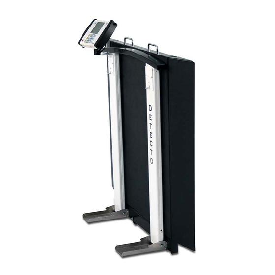
- Page 1 Model 6560 Portable Wheelchair Scale Service Manual 0065-0729-0M – 6560 Service Manual...
-
Page 2: Fcc Compliance Statement
Seller is not able to guarantee the result of any procedure contained herein. Nor can they assume responsibility for any damage to property or injury to persons occasioned from the procedures. Persons engaging the procedures do so entirely at their own risk. 0065-0729-0M – 6560 Service Manual... -
Page 3: Care And Cleaning
If required, a mild solvent such as mineral spirits can be used to remove oil, grease, tars, wax, and similar substances. Use a cloth dampened with mineral spirits and apply only to areas that are contaminated. Follow up the use of this mild solvent with detergent cleaning and rinsing. 0065-0729-0M – 6560 Service Manual... - Page 4 0065-0729-0M – 6560 Service Manual...
- Page 5 MODEL 6560 PORTABLE WHEELCHAIR SCALE TEST PROCEDURE A. Equipment Required B. Scale Trim Adjustment C. Calibration D. Final Test 0065-0729-0M – 6560 Service Manual...
- Page 6 Change the value by entering the new data using the numeric keypad, and then pressing the PRINT/ENTER key. 7. Follow the prompts listed in the MEDVUE SETUP TABLE. 0065-0729-0M – 6560 Service Manual...
- Page 7 MONTH [1-12] = Enter current day of the month dAY [1-31] =. Enter current hour in 24-hour format HOUR [0-23] = Enter current minute MINUTE [0-59] = Enter current second SECONd [0-59] = 24 HOUR TIME = 0065-0729-0M – 6560 Service Manual...
-
Page 8: Final Test
400 lb 399.8 lb To 400.2 lb 500 lb 499.8 lb- To 500.2 lb+ 5+2+3 900 lb 899.4 lb To 900.6 lb Then 5+1+4 Weight Positions Use these weights for Corner Test For Corner Test 0065-0729-0M – 6560 Service Manual... - Page 9 5-10 seconds. NOTE: Most adhesive backed items will not attain full strength until after 24 hours. It is critical that the above procedure be followed to obtain the maximum bonding strength of any adhesive. 0065-0729-0M – 6560 Service Manual...
-
Page 10: Parts Identification
PARTS IDENTIFICATION Final Assembly – 0065-0680-0A ITEM PART NUMBER DESCRIPTION 0065-0703-0A UNIV. BASE ASSY 6560/6570 0065-0807-0A 6560 COL. AND LATCH ASSY RH 0065-0808-0A 6560 COL. AND LATCH ASSY LH 0065-0689-0A 6570 HANDRAIL WELDMENT 6021-1454 1/4-20 x .750, ZP 6021-1127 SCW PAN-HEAD, SELF-TAP...6- 32X.5... - Page 11 PARTS IDENTIFICATION, CONT. Final Assembly – 0065-0680-0A, Front and Section A-A View 0065-0729-0M – 6560 Service Manual...
- Page 12 PARTS IDENTIFICATION, CONT. Final Assembly – 0065-0680-0A, Side, Detail B and C View 0065-0729-0M – 6560 Service Manual...
- Page 13 PARTS IDENTIFICATION, CONT. Final Assembly – 0065-0680-0A, Wiring Schematic 0065-0729-0M – 6560 Service Manual...
- Page 14 PARTS IDENTIFICATION, CONT. 6560/6570 Universal Base Assembly – 0065-0703-0A ITEM PART NUMBER DESCRIPTION 0065-0702-0A 6560/6570 WB WELDMENT 0065-B539-08 LATCH COVER PLATE, 14 GA, SS 304 HR BTTM BASE/DUAL COLUMN, 0065-0678-08 3 X 1-1/2 X 3/16 WALL TUBING 0065-0716-08 LFB-250P 6540-1624...
- Page 15 2. HR BTTM base/dual column (item 3) must be attached to deck (item 1) before installation of load cells (item 4). 3. Apply Loctite (6560-1126) to threads of bolt before installation. 4. Ramps can be attached for alignment and positioning of load cells. Ramps will be removed with rubber mounts (item 5) left installed in load cells for calibration and packaging.
- Page 16 PARTS IDENTIFICATION, CONT. 6560/6570 Universal Base Assembly – 0065-0703-0A 0065-0729-0M – 6560 Service Manual...
- Page 17 PARTS IDENTIFICATION, CONT. 6560/6570 Universal Base Assembly – 0065-0703-0A Section A-A, Detail B, and Section C-C View 0065-0729-0M – 6560 Service Manual...
- Page 18 PARTS IDENTIFICATION, CONT. LH Column and Latch Assembly – 0065-0808-0A ITEM PART NUMBER DESCRIPTION 0065-0786-0A COLUMN WELDMENT LH - 6560 0065-0758-0A COL. FACE SPOT WELD ASSY 6549DS COLUMN SWIVEL BASE, 0065-0697-08 SS SHT 12 GA.X48X96 0065-B342-08 PIN - COLUMN PIVOT, SS RD 1/4 X 12 FT 399R40 PUSH NUT, 1/4"...
- Page 19 CABLE, INDICATOR 6013-0295 NUT #10-32 HEX Z/P 6021-0665 MACHINE-SCW 06-32X.375 6028-0093 PIN HITCH 6028-0094 SPLIT RING 6680-1014 CHAIN NOTES: 1. Apply Loctite (6560-1061) to threads of bolt. 2. Remove paint from parts as necessary for assembly. 0065-0729-0M – 6560 Service Manual...
- Page 20 PARTS IDENTIFICATION, CONT. LH Column and Latch Assembly – 0065-0808-0A 0065-0729-0M – 6560 Service Manual...
- Page 21 PARTS IDENTIFICATION, CONT. LH Column and Latch Assembly – 0065-0808-0A, Detail B and C 0065-0729-0M – 6560 Service Manual...
- Page 22 NUT #10-32 HEX Z/P 6021-0665 MACHINE-SCW 06-32X.375 LATCH COVER 6560, 0065-0695-08 HRPO SHT 12 GA. X 48 X 96 NOTES: 1. Apply Loctite (6560-1061) to threads of bolt. 2. Remove paint from parts as necessary for assembly. 0065-0729-0M – 6560 Service Manual...
- Page 23 PARTS IDENTIFICATION, CONT. RH Column and Latch Assembly – 0065-0807-0A 0065-0729-0M – 6560 Service Manual...
- Page 24 PARTS IDENTIFICATION, CONT. RH Column and Latch Assembly – 0065-0807-0A, Detail B and C 0065-0729-0M – 6560 Service Manual...
-
Page 25: Statement Of Limited Warranty
(2) years from date of shipment. Detecto shall be the sole judge of what constitutes a defect. During the first ninety (90) days Detecto may choose to replace the product at no charge to the buyer upon inspection of the returned item. - Page 26 Cardinal Scale Manufacturing Co. 203 E. Daugherty, Webb City, MO 64870 USA Ph: 417-673-4631 or 1-800-641-2008 Fax: 417-673-2153 Technical Support: 1-866-254-8261 Printed in USA E-mail: tech@cardet.com 0065-0729-0M Rev A 09/18 0065-0729-0M – 6560 Service Manual...
Need help?
Do you have a question about the 6560 and is the answer not in the manual?
Questions and answers