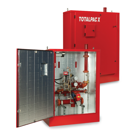
FireFlex TOTALPAC X Owner's Operation And Maintenance Manual
Advanced integrated fire protection system
Hide thumbs
Also See for TOTALPAC X:
- Owner's operation and maintenance manual (26 pages) ,
- Owner's operation and maintenance manual (36 pages) ,
- Owner's operation and maintenance manual (24 pages)

Related Manuals for FireFlex TOTALPAC X


Summary of Contents for FireFlex TOTALPAC X
- Page 1 Advanced Integrated Fire Protection System ® OTAL Owner's Operation Maintenance Manual YSTEM FM-076G-0-19A...
- Page 2 ® OTAL Page ii Integrated Fire Protection System & M WNER PERATION AINTENANCE ANUAL Copyright © 2021 F Systems Inc. All Rights Reserved Reproduction or use, without express written permission from F Systems Inc, of any portion of this manual is prohibited. While all reasonable efforts have been taken in the preparation of this manual to assure its accuracy, F Systems Inc assumes no liability resulting from any errors or omissions in this manual, or from the use of the information contained herein.
-
Page 3: Table Of Contents
® OTAL Page iii Integrated Fire Protection System & M WNER PERATION AINTENANCE ANUAL Table of Contents Wet Pipe System General Section ......................Section 1- General description 2- Listings and approvals 3- Applicable standards 4- Environment 5- Features 6- Configuration description 7- System release Mechanical Section ........................ - Page 4 ® OTAL Page iv Integrated Fire Protection System & M WNER PERATION AINTENANCE ANUAL This page is left intentionally blank. FM-076G-0-19A...
- Page 5 ® OTAL Page 1 of 2 Integrated Fire Protection System General Section - Wet Pipe System 2- Listings and approvals 1- General description In addition to being fabricated under tight ISO-9001 ® This T X integrated fire protection system by OTAL manufacturing and quality control procedures, your Systems Inc.
-
Page 6: General Section
® OTAL Page 2 of 2 Integrated Fire Protection System General Section - Wet Pipe System 5- Features 6- Configuration description ® ® The T X unit is superior to many other products X wet pipe system is built around the Viking OTAL OTAL which are actually available on the fire protection market. -
Page 7: Mechanical Section
® OTAL Page 1 of 8 Integrated Fire Protection System Mechanical Section - Wet Pipe System 1- Installation, operation & maintenance instructions 1.2 Preliminary inspection before placing the system in Note: Numbers indicated between brackets refer service figures 1 and 2 DETAILED SYSTEM TRIM SCHEMATICS. 1. -
Page 8: Placing The System In Service
® OTAL Page 2 of 8 Integrated Fire Protection System Mechanical Section - Wet Pipe System 1.4 System Operation 1.3 Placing the system in service 1.4.1 In the SET condition 1. Verify that the main water supply valve (D1) is CLOSED and that the system is free of leaks. -
Page 9: Emergency Instructions
® OTAL Page 3 of 8 Integrated Fire Protection System Mechanical Section - Wet Pipe System 1.6 Placing the system back in service after operation 1.5 Emergency instructions 1. Verify that the system has been properly drained. Verify To take system out of service that all automatic sprinklers are set and system piping auxiliary drain valves are CLOSED. -
Page 10: Maintenance
® OTAL Page 4 of 8 Integrated Fire Protection System Mechanical Section - Wet Pipe System 1.7 Inspections and tests 1.8 Maintenance NOTICE : The owner is responsible for maintaining the fire NOTICE: The owner is responsible for maintaining the fire protection system and devices in proper operating protection system and devices in proper operating condition. -
Page 11: Normal Condition
® OTAL Page 5 of 8 Integrated Fire Protection System Mechanical Section - Wet Pipe System 1.8.2 Quarterly 2- Wet pipe system 1. Check alarm pressure switch (C1) and optional water Note: Numbers indicated between brackets refer to figure 1 motor gong (C2) by opening the alarm test valve (B5). - Page 12 ® OTAL Page 6 of 8 Integrated Fire Protection System Mechanical Section - Wet Pipe System Figure 1 - Detailed system trim schematic for wet pipe system with excess pressure pump Typical wet pipe system with excess pressure pump (4" (100 mm) system shown) FIELD CONNECTION TO SPRINKLER PIPING NETWORK B7 B8...
- Page 13 ® OTAL Page 7 of 8 Integrated Fire Protection System Mechanical Section - Wet Pipe System Figure 2 - Detailed system trim schematic for wet pipe system with retard chamber Typical wet pipe system with retard chamber (4" (100 mm) system shown) FIELD CONNECTION TO SPRINKLER PIPING NETWORK FIELD CONNECTION...
- Page 14 ® OTAL Page 8 of 8 Integrated Fire Protection System Mechanical Section - Wet Pipe System This page is left intentionally blank. FM-076G-0-59A...
-
Page 15: Control Section
® OTAL Page 1 of 4 Integrated Fire Protection System Control Section 1. Remotely supervised unit without control panel 1.1 Product description 1.2 Technical data ® CABINET SECTION for The T X wet pipe unit is provided without control Steel enclosure: Refer to section OTAL panel. - Page 16 ® OTAL Page 2 of 4 Integrated Fire Protection System Control Section Figure 2 - Typical wet pipe system layout with retard chamber Junctions Box Optional Light & Door Switch TBA, TBB & TBC Retard Chamber Typical Wet Pipe Trim Drain Outlet Water Inlet Door Lock (4)
- Page 17 ® OTAL Page 3 of 4 Integrated Fire Protection System Control Section Figure 3 - Junctions box layout for wet pipe system with excess pressure pump, without control panel AC POWER 120VAC, 60Hz or POWER LIMITED CIRCUITS 220/240VAC, 50/60Hz All conduits are installed by the Contractor TBB Terminals TBA &...
- Page 18 ® OTAL Page 4 of 4 Integrated Fire Protection System Control Section Figure 4 - Junctions box layout for wet pipe system with retard chamber, without control panel AC POWER 115VAC, 60Hz or POWER LIMITED CIRCUITS 230VAC, 50/60Hz All conduits are installed by the Contractor TBB Terminals TBA &...
- Page 19 ® OTAL Page 1 of 2 Integrated Fire Protection System Electrical Section - Wet Pipe System 1. Remotely supervised configuration for wet pipe system with excess pressure pump ® This T X unit has been provided without an OTAL Note : No connection should be made directly in the trim integrated control panel since all internal supervisory components as this would void warranty and might prevent devices are to be connected and supervised from a remote...
- Page 20 ® OTAL Page 2 of 2 Integrated Fire Protection System Electrical Section - Wet Pipe System 2. Remotely supervised configuration for wet pipe system with retard chamber ® This T X unit has been provided without an OTAL Note : No connection should be made directly in the trim integrated control panel since all internal supervisory components as this would void warranty and might prevent devices are to be connected and supervised from a remote...
-
Page 21: Dimensional Data & Cabinet
® OTAL Page 1 of 4 Integrated Fire Protection System Dimensional Data & Cabinet ® 1- Cabinet for T X unit OTAL ® The T X unit cabinet is made of sturdy 14 gauge OTAL ® IMPORTANT ! T X unit is designed to be installed OTAL steel. - Page 22 ® OTAL Page 2 of 4 Integrated Fire Protection System Dimensional Data & Cabinet Figure 1 - Cabinet and inlets/outlets dimensions ØB TBA, TBB & TBC DRAIN - SCH.40 GROOVED OUTLET ØC WATER INLET SCH.40 GROOVED OUTLET ØA TBA, TBB & TBC ØC ØA ØB...
- Page 23 ® OTAL Page 3 of 4 Integrated Fire Protection System Dimensional Data & Cabinet Figure 2 - Floor anchoring dimensions Table 3 - Floor anchoring dimensions 4½" (114mm) Unit size 3" 41" 16" (1041mm) (406mm) 4½" (114mm) (80mm) 4" 41" 16"...
- Page 24 ® OTAL Page 4 of 4 Integrated Fire Protection System Dimensional Data & Cabinet This page is left intentionally blank. FM-076G-0-109A...
-
Page 25: Limited Warranty
Manufacturer with respect to its Tel.: (450) 437-3473 products. This warranty shall not be modified, unless such Fax: (450) 437-1930 modification is made in writing by an executive officer of Toll Free: (866) 347-3353 the Manufacturer. Website: www.fireflex.com FM-076G-0-84B... - Page 26 ® OTAL Page 2 of 2 Integrated Fire Protection System Limited Warranty User Notes FM-076G-0-84B...
Need help?
Do you have a question about the TOTALPAC X and is the answer not in the manual?
Questions and answers