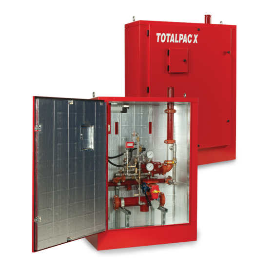
FireFlex TOTALPAC X Owner's Operation And Maintenance Manual
Advanced integrated fire protection system
Hide thumbs
Also See for TOTALPAC X:
- Owner's operation and maintenance manual (26 pages) ,
- Owner's operation and maintenance manual (26 pages) ,
- Owner's operation and maintenance manual (24 pages)

Related Manuals for FireFlex TOTALPAC X


Summary of Contents for FireFlex TOTALPAC X
- Page 1 Advanced Integrated Fire Protection System ® OTAL Owner's Operation Maintenance Manual OUBLE NTERLOCK REACTION YSTEM RELEASE ® FM-076G-0-11A...
- Page 2 ® OTAL Page ii Integrated Fire Protection System & M WNER PERATION AINTENANCE ANUAL Copyright © 2021 F Systems Inc. All Rights Reserved Reproduction or use, without express written permission from F Systems Inc, of any portion of this manual is prohibited. While all reasonable efforts have been taken in the preparation of this manual to assure its accuracy, F Systems Inc assumes no liability resulting from any errors or omissions in this manual, or from the use of the information contained herein.
-
Page 3: Table Of Contents
® OTAL Page iii Integrated Fire Protection System & M WNER PERATION AINTENANCE ANUAL Table of Contents ® Double Interlock Preaction System - S Release General Section ......................Section 1- General description 2- Listings and approvals 3- Applicable standards 4- Environment 5- Features 6- Configuration description 7- System release... - Page 4 ® OTAL Page iv Integrated Fire Protection System & M WNER PERATION AINTENANCE ANUAL This page is left intentionally blank. FM-076G-0-11A...
-
Page 5: Double Interlock Preaction System - Sure Fire ® Release
® ® OTAL Page 1 of 2 Integrated Fire Protection System ® General Section - Double Interlock Preaction System - S Release 2- Listings and approvals 1- General description In addition to being fabricated under tight ISO-9001 ® ® This T integrated fire protection OTAL manufacturing and quality control procedures, your... -
Page 6: 5- Features
® ® OTAL Page 2 of 2 Integrated Fire Protection System ® General Section - Double Interlock Preaction System - S Release 5- Features ® ® The T unit is superior to many other OTAL 6.1 Double interlock preaction system products which are actually available on the fire protection The system piping network is pressurized with air or market. -
Page 7: Mechanical Section
® ® OTAL Page 1 of 8 Integrated Fire Protection System ® Mechanical Section - Double Interlock Preaction System - S Release 1- Installation, operation & maintenance instructions 1.2 Preliminary inspection before placing the system in Note: Numbers indicated between brackets refer to figure 1 service DETAILED SYSTEM TRIM SCHEMATICS from this section and AIR SUPPLY. -
Page 8: Placing The System In Service
® ® OTAL Page 2 of 8 Integrated Fire Protection System ® Mechanical Section - Double Interlock Preaction System - S Release 1.4 System Operation 1.3 Placing the system in service 1.4.1 In the SET condition 1. Verify that the main water supply valve (D1) is CLOSED. Verify that the system has been properly drained. -
Page 9: Emergency Instructions
® ® OTAL Page 3 of 8 Integrated Fire Protection System ® Mechanical Section - Double Interlock Preaction System - S Release 1.6 Placing the system back in service after operation 1.4.5 Fail-safe condition 1. Verify that the system has been properly drained. Verify If the remote release control panel is unable to energize that all automatic sprinklers are set and/or inspector's the solenoid valve (F1), the system will operate as a dry... - Page 10 ® ® OTAL Page 4 of 8 Integrated Fire Protection System ® Mechanical Section - Double Interlock Preaction System - S Release 1.7 Inspections and tests 1.7.2 Full flow trip test Performance of a full flow trip test is recommended NOTICE: The owner is responsible for maintaining the fire annually during warm weather.
-
Page 11: Maintenance
® ® OTAL Page 5 of 8 Integrated Fire Protection System ® Mechanical Section - Double Interlock Preaction System - S Release 1.7.4 Operation of the optional shut-off valve 1.8 Maintenance Inspection of the system can be implemented without filling NOTICE: The owner is responsible for maintaining the fire the system piping network with water. -
Page 12: Normal Condition
® ® OTAL Page 6 of 8 Integrated Fire Protection System ® Mechanical Section - Double Interlock Preaction System - S Release 1.8.3 Semi-annually 2- Double interlock preaction system with ® release 1. Main water supply valve (D1) switch shall be operated to verify the switch actuation upon movement of the hand wheel. - Page 13 ® ® OTAL Page 7 of 8 Integrated Fire Protection System Mechanical Section - Double Interlock Preaction System - S ® Release Figure 1 - Detailed system trim schematic Typical double interlock preaction system with S ® release (3" (80 mm) system shown) FIELD CONNECTION TO SPRINKLER PIPING NETWORK CONTRACTOR'S...
- Page 14 ® ® OTAL Page 8 of 8 Integrated Fire Protection System ® Mechanical Section - Double Interlock Preaction System - S Release This page is left intentionally blank. FM-076G-0-52A...
-
Page 15: Trim Options
® OTAL Page 1 of 2 Integrated Fire Protection System Trim Options Preaction trim options 1. Shut-off valve & sight glass 2. Anti-column device option The shut-off valve & sight glass option is intended to be The model LD-1 anti-column device is an optional trim used for applications where testing of the system operation component designed for use with preaction sprinkler without filling the sprinkler piping network is desirable and... - Page 16 ® OTAL Page 2 of 2 Integrated Fire Protection System Trim Options This page is left intentionally blank. FM-076G-0-61B...
- Page 17 ® OTAL Page 1 of 10 Integrated Fire Protection System Air Supply - Preaction System 1. Cabinet Air Supplies 1.2 Air supply Style "B" (refer to figure 3) Preaction sprinkler system using pressure supervisory or releasing purposes is provided with either Used only for the sprinkler piping network of preaction internal or external supervised air supply.
- Page 18 ® OTAL Page 2 of 10 Integrated Fire Protection System Air Supply - Preaction System 2. Operation 2.1 Air supply Style "A" (refer to figure 2) 2.2 Air supply Style "B" (refer to figure 3) To apply air supply To apply air supply Establish AC power for the air compressor by activating 1.
- Page 19 ® OTAL Page 3 of 10 Integrated Fire Protection System Air Supply - Preaction System 3. Maintenance and inspection 3.2 Air supply Style "B" (refer to figure 3) IMPORTANT : Advise local authorities of the necessary The Viking Model D-2 APMD (air pressure maintenance work over the fire protection equipment.
-
Page 20: Air Supply
® OTAL Page 4 of 10 Integrated Fire Protection System Air Supply - Preaction System Table 2 - Water pressure up to 175 PSI (1207 kPa) Air supply Compressor Compressor Low air Low air System type Style regulator start stop supervisory alarm 15 PSI... - Page 21 ® OTAL Page 5 of 10 Integrated Fire Protection System Air Supply - Preaction System Figure 2 - Air supply Style "A" TO OPTIONAL ACCELERATOR OR PNEUMATIC ACTUATOR (plugged when not used) Joint tubing Pressure relief valve (plug connection applies according to system configuration) TO DRAIN COLLECTOR TO SPRINKLER RISER...
- Page 22 ® OTAL Page 6 of 10 Integrated Fire Protection System Air Supply - Preaction System Figure 3 - Air supply Style "B" Contractor external Air or Nitrogen connection TO OPTIONAL ACCELERATOR TO SPRINKLER RISER OR PNEUMATIC ACTUATOR (plugged when not used) (plug connection applies according to system configuration) FM-086V-0-16A...
- Page 23 ® OTAL Page 7 of 10 Integrated Fire Protection System Air Supply - Preaction System Figure 4 - Air supply Style "D" Air supply connection for external air supply TO OPTIONAL ACCELERATOR TO SPRINKLER RISER OR PNEUMATIC ACTUATOR (plugged when not used) (plug connection applies according to system configuration) Contractor external air...
-
Page 24: 4- Air Supply Options
® OTAL Page 8 of 10 Integrated Fire Protection System Air Supply - Preaction System 4. Air supply options 4.1 Accelerator To reset the accelerator device The Viking Model E-1 accelerator is a quick-opening Make sure the system is properly drained and reset. device featuring automatic reset. - Page 25 ® OTAL Page 9 of 10 Integrated Fire Protection System Air Supply - Preaction System 4. Verify that all other trim valves are in their normal 3. Check the upper chamber pressure of the accelerator. operating position. The air pressure should be equal to the air pressure maintained in the system on which it is installed.
- Page 26 ® OTAL Page 10 of 10 Integrated Fire Protection System Air Supply - Preaction System This page is left intentionally blank. FM-076G-0-119A...
-
Page 27: Control Section
® OTAL Page 1 of 2 Integrated Fire Protection System Control Section 1. Remotely controlled unit without release control panel 1.1 Product description 1.2 Technical data CABINET SECTION for ® Steel enclosure: Refer to section The T X preaction unit is provided without OTAL release control panel. - Page 28 ® OTAL Page 2 of 2 Integrated Fire Protection System Control Section Figure 2 - Junctions box layout for system without release control panel AC POWER 120VAC, 60Hz or POWER LIMITED CIRCUITS 220/240VAC, 50/60Hz All conduits are installed by the Contractor TBB Terminals TBA &...
-
Page 29: Electrical Section
® ® OTAL Page 1 of 2 Integrated Fire Protection System Electrical Section - Double Interlocked Preaction System - S ® Release 1. Remotely controlled configuration ® ® The T remote controlled unit is OTAL Notes : No connection should be made directly in the trim provided without an integrated control panel since all components as this would void warranty and might prevent internal supervisory and releasing devices are to be... - Page 30 ® ® OTAL Page 2 of 2 Integrated Fire Protection System ® Electrical Section - Double Interlocked Preaction System - S Release Table 1 - Solenoid valves electrical ratings SOLENOID VALVES ELECTRICAL RATINGS Operation Viking P/N Voltage Watt DC amp (de-energized) 11591 N.C.
-
Page 31: Dimensional Data & Cabinet
® OTAL Page 1 of 4 Integrated Fire Protection System Dimensional Data & Cabinet ® 1- Cabinet for T X unit OTAL ® The T X unit cabinet is made of sturdy 14 gauge OTAL ® IMPORTANT ! T X unit is designed to be installed OTAL steel. - Page 32 ® OTAL Page 2 of 4 Integrated Fire Protection System Dimensional Data & Cabinet Figure 1 - Cabinet and inlets/outlets dimensions ØB TBA, TBB & TBC DRAIN - SCH.40 GROOVED OUTLET ØC WATER INLET SCH.40 GROOVED OUTLET ØA TBA, TBB & TBC ØC ØA ØB...
- Page 33 ® OTAL Page 3 of 4 Integrated Fire Protection System Dimensional Data & Cabinet Figure 2 - Floor anchoring dimensions Table 3 - Floor anchoring dimensions 4½" (114mm) Unit size 1½ 41" 16" (1041mm) (406mm) 4½" (114mm) (40mm) 2" 41" 16"...
- Page 34 ® OTAL Page 4 of 4 Integrated Fire Protection System Dimensional Data & Cabinet This page is left intentionally blank. FM-076G-0-108A...
-
Page 35: Limited Warranty
Manufacturer with respect to its Tel.: (450) 437-3473 products. This warranty shall not be modified, unless such Fax: (450) 437-1930 modification is made in writing by an executive officer of Toll Free: (866) 347-3353 the Manufacturer. Website: www.fireflex.com FM-076G-0-84B... - Page 36 ® OTAL Page 2 of 2 Integrated Fire Protection System Limited Warranty User Notes FM-076G-0-84B...
Need help?
Do you have a question about the TOTALPAC X and is the answer not in the manual?
Questions and answers