Table of Contents
Advertisement
Advanced Integrated Fire Protection Systems
®
T
P
2
OTAL
AC
Owner's Operation
and
Maintenance Manual
D
ELUGE
September 2009
FM-086G-0-6F
Advertisement
Table of Contents

Related Manuals for FireFlex TOTALPAC2


Summary of Contents for FireFlex TOTALPAC2
- Page 1 Advanced Integrated Fire Protection Systems ® OTAL Owner's Operation Maintenance Manual ELUGE September 2009 FM-086G-0-6F...
- Page 2 2 Integrated Fire Protection System OTAL & M WNER PERATION AINTENANCE ANUAL FireFlex Systems Inc. Manufactured by 1935 Lionel-Bertrand Blvd Boisbriand, QC (Canada) J7H 1N8 Tel: (450) 437-3473 Toll free: (866) 347-3353 Fax: (450) 437-1930 info@fireflex.com Web Site: http://www.fireflex.com - E-Mail: FM-086G-0-6F...
- Page 3 OTAL 2 Integrated Fire Protection System OTAL & M WNER PERATION AINTENANCE ANUAL Table of contents Deluge Description Form N General ............................FM-086G-0-15 1- Applicable standards 2- Listings & Approvals 3- Environment 4- General description 5- Features 6- Configuration Description 7- Release systems 7a- Hydraulic Release 7b- Pneumatic Release...
- Page 4 OTAL 2 Integrated Fire Protection System OTAL & M WNER PERATION AINTENANCE ANUAL Table of contents (cont'd) Deluge Description Form N Programming Section ......................FM-086G-0-38 1- Remote controlled, Pneumatic Release 2- Remote controlled, Hydraulic Release 2- Remote controlled, Electric Release 4- Self-Contained Unit, Electric Release System Design and Dimensional Data ..................
- Page 5 ® is a registered trademark of FireFlex Systems Inc. OTAL FireFlex Systems Inc. reserves the right to make changes to this manual and the data sheets herewith at any time, without prior notification. FM-086G-0-6F...
- Page 6 OTAL 2 Integrated Fire Protection System OTAL & M WNER PERATION AINTENANCE ANUAL TOTALPAC FM-086G-0-6F...
- Page 7 Preaction TotalPac2 systems are CSFM Approved under the heading: Misc. Devices/Control Unit Accessories, Listing No. 7300-0533:107. - City of New York: Deluge TotalPac2 systems are Approved under the Certificate of Approval # 6021. (electric release only) Note: Although most T...
- Page 8 2 integrated fire protection system by OTAL - Unique serial number on every unit FireFlex Systems Inc. consists of a deluge system trim totally pre-assembled, pre-wired and factory tested. All - Uses only UL, C-UL Listed and FM Approved components...
- Page 9 OTAL Page 3 of 4 2 Integrated Fire Protection System OTAL General Section - Deluge System 6. Configurations Description 7. Release Systems A Deluge system is a fixed fire-protection system which Hydraulic Hydraulic Release. ally controlled Deluge totally floods an area with pressurized water through a systems require a hydraulic release system, equipped with system piping of open nozzles or sprinklers.
- Page 10 OTAL Page 4 of 4 2 Integrated Fire Protection System OTAL General Section - Deluge System This page was intentionally left blank FM-086G-0-15E...
- Page 11 7. If the system does not operate as it should, make the operation of one of the release systems described necessary corrections according to manuals issued or above. For specific trim arrangement, refer to the consult your distributor or FireFlex Systems Inc. MECHANICAL TRIM DESCRIPTION. 8. Make sure that...
- Page 12 OTAL Page 2 of 12 2 Integrated Fire Protection Systems OTAL Mechanical Section - Deluge System 1.3 Placing the system in service: Important Settings Release Piping Pressures. (Refer to MECHANICAL TRIM DESCRIPTION and TRIM SCHEMATIC) Deluge Systems with Pneumatic Release Verify the following: (also refer to Table 1 below): a) The system Main Water Supply Control Valve (D1) is...
- Page 13 OTAL Page 3 of 12 2 Integrated Fire Protection Systems OTAL Mechanical Section - Deluge System Water will flow from all the open sprinklers and/or nozzles in Deluge systems with Hydraulic Release: the system. Alarm Pressure Switch (C1) should activate when pressurized to 4 to 8 psi (27 to 55 kPa) on pressure When the deluge valve operates, the sensing end of the rise.
- Page 14 OTAL Page 4 of 12 2 Integrated Fire Protection Systems OTAL Mechanical Section - Deluge System 1.5 Emergency Instructions 1.6 Placing the system back in service after operation: (Refer to piping diagram provided) (refer to TRIM SCHEMATIC) To take system Out of Service: Verify that the system has been properly drained (in cycling systems, System Main Water Supply Control Warning ! Placing a control valve or detection system out of...
- Page 15 OTAL Page 5 of 12 2 Integrated Fire Protection Systems OTAL Mechanical Section - Deluge System 1.7 Inspections & Tests 6. Fully open and secure the Main Water Supply Control Valve (D1). It is imperative that the system be inspected on a regular 7.
- Page 16 OTAL Page 6 of 12 2 Integrated Fire Protection Systems OTAL Mechanical Section - Deluge System 1.8 MAINTENANCE Quarterly: Note: The owner is responsible for maintaining the fire Alarm Device (pressure or flow switch). (Testing by protection system and devices in proper operating opening the inspector's test connection).
- Page 17 OTAL Page 7 of 12 2 Integrated Fire Protection Systems OTAL Mechanical Section - Deluge System 2. Normal condition 2- System with Hydraulic Release 1. Valves a) Main water supply control valve (D1) is OPEN. 1. Description b) All upstream water supply valves are OPEN. The T 2 System with the Viking Deluge Trim utilizes OTAL...
- Page 18 OTAL Page 8 of 12 2 Integrated Fire Protection Systems OTAL Mechanical Section - Deluge System Release Trim Schematic: Deluge System with Hydraulic Trim Components: Valve: Water Flow Alarm Equipment: Deluge valve Alarm pressure switch Connection to water motor gong (strainer supplied by contractor) Deluge Valve Trim: Priming valve...
- Page 19 OTAL Page 9 of 12 2 Integrated Fire Protection Systems OTAL Mechanical Section - Deluge System 2. Normal condition 3- System with Pneumatic Release 1. Valves 1. Description a) Main water supply control valve (D1) is OPEN. b) All upstream water supply valves are OPEN. The T 2 System with the Viking Deluge Trim utilizes OTAL...
- Page 20 OTAL Page 10 of 12 2 Integrated Fire Protection Systems OTAL Mechanical Section - Deluge System Trim Schematic: System with Pneumatic release Trim Components: Valve: Water Flow Alarm Equipment: Deluge valve Alarm pressure switch Connection to water motor gong (strainer supplied by contractor) Deluge Valve Trim: Priming valve...
- Page 21 OTAL Page 11 of 12 2 Integrated Fire Protection Systems OTAL Mechanical Section - Deluge System 2. Normal condition 4- Deluge System with Electric Release 1. Control panel of the T 2 system OTAL 1. Description a) Green lamp identified "AC POWER" lights up. b) All other lamps are off.
- Page 22 OTAL Page 12 of 12 2 Integrated Fire Protection Systems OTAL Mechanical Section - Deluge System Trim Schematic: System with electric release Trim Components: Valve: C. Water Flow Alarm Equipment: Deluge valve Alarm pressure switch Connection to water motor gong (strainer supplied by contractor) Deluge Valve Trim: Priming valve...
- Page 23 OTAL Page 1 of 2 2 Integrated Fire Protection System OTAL Trim Options 1. Shut-Off Valve & Sight Glass: 2. Fire Department Connection: The Shut-off Valve & Sight Glass Option is intended to be The Fire Department Connection Option consists of a used for applications where testing of the system operation grooved Tee fitting installed in lieu of the 90 degree elbow at without filling the sprinkler piping network is desirable and...
- Page 24 3. Semi and Full-flanged Option: The full flanged option is the same as above but goes a step When required by the user, TotalPac2 units can be provided further with the main components being also provided with a in either a semi-flanged of full flanged configuration.
- Page 25 OTAL Page 1 of 14 2 Integrated Fire Protection System OTAL Air Supply 1- Cabinet Air Supplies Ambient temperature at the special external air supply unit Preaction, dry valve and other sprinkler systems using air location should not exceed 104 F (40 C).
- Page 26 OTAL Page 2 of 14 2 Integrated Fire Protection System OTAL Air Supply 1.2 Connecting the Air Compressor to AC power 1.3.2 To close air supply: Turn off the compressor isolating switch (E15). The motor must be protected against short circuit, overload and excessive temperature rise.
- Page 27 OTAL Page 3 of 14 2 Integrated Fire Protection System OTAL Air Supply 2. To remove and clean the check valve assembly (E11): Air supplies style "B" or "C": This procedure requires turning OFF the compressor's AC 1. To Apply Air Supply: power.
- Page 28 OTAL Page 4 of 14 2 Integrated Fire Protection System OTAL Air Supply If adjustment is necessary, refer to paragraph 1.3 of • 4. To drain the Air Supply Accumulator: the current Section The amount of moisture pumped into the system and how The APMD (E5) should be checked for correct pressure quickly it accumulates is proportional to the amount of regulation after installation or repair by noting the air...
- Page 29 OTAL Page 5 of 14 2 Integrated Fire Protection System OTAL Air Supply Figure 1 – Air Supply Style "A" (Cabinet mounted air compressor) Air compressor filter Copper tubing To sprinklers riser Plug removed for Optional accelerator or Pneumatic actuator (when used) Pipe replaced by Dehydrator Option...
- Page 30 OTAL Page 6 of 14 2 Integrated Fire Protection System OTAL Air Supply Figure 2 – Air Supply Style "B" (APMD without air compressor) Note: The external air supply must be restricted to insure that it cannot replace air as fast as it escapes when a releasing device or sprinkler operates.
- Page 31 OTAL Page 7 of 14 2 Integrated Fire Protection System OTAL Air Supply Figure 3 – Air Supply Style "C" (APMD for Pilot Line release system only) Air Option Components: Optional Components: (see Air Supply Options for details) System air pressure gauge - Accelerator Air supervisory pressure switch Air pressure maintenance device (APMD)
- Page 32 OTAL Page 8 of 14 2 Integrated Fire Protection System OTAL Air Supply (Air supply connection only for external air supply) Figure 4 – Air Supply Style "D" E4 (replaced by a plug on SUREFIRE trim) Note: The external air supply must be restricted to insure that it cannot replace air as fast as it escapes when a releasing device or sprinkler operates.
- Page 33 OTAL Page 9 of 14 2 Integrated Fire Protection System OTAL Air Supply Table 1: Water Pressure up to 175 Psi Air Supply Compressor Compressor Low Air Low Air System Type Style Regulator Start Stop Supervisory Alarm 30 Psi 35 Psi 25 Psi Non-Interlocked (207 kPa)
- Page 34 OTAL Page 10 of 14 2 Integrated Fire Protection System OTAL Air Supply Table 2: Water Pressure from 175 Psi to 250 Psi Air Supply Compressor Compressor Low Air Low Air System Type Style Regulator Start Stop Supervisory Alarm 50 Psi 55 Psi 45 Psi Non-Interlocked...
- Page 35 Air Supply 2- Skid Air Supply Option 2.2 Operation .1 To Apply Air Supply: When TotalPac2 units are provided in skid form, the air supply is provided by the installing contractor. Preaction, dry Turn on upstream air supply. Open Air shut-off valve and other sprinkler systems skids using air pressure for valve (E14) by placing handle in line with valve body.
- Page 36 OTAL Page 12 of 14 2 Integrated Fire Protection System OTAL Air Supply Figure 1 – Skid Air Supply for Sprinklers Network (Air supply connection only for external air supply ) Note: The external air supply must be restricted to insure that it cannot replace air as fast as it escapes when a releasing device or sprinkler operates.
- Page 37 OTAL Page 13 of 14 2 Integrated Fire Protection System OTAL Air Supply Figure 2 – Skid Air Supply for Pilot Line (Air supply connection only for external air supply ) Note: The external air supply must be restricted to insure that it cannot replace air as fast as it escapes when a releasing device or sprinkler operates.
- Page 38 OTAL Page 14 of 14 2 Integrated Fire Protection System OTAL Air Supply This page was intentionally left blank FM-086G-0-43E...
- Page 39 OTAL Page 1 of 2 2 Integrated Fire Protection System OTAL Air Supply Dehydrator Option Viking Dehydrator: The unit is to be used on compressed air service only. The Viking Dehydrator is a manually regenerated desiccant- type air dryer. The desiccant acts as a moisture indicator by Operation of Dehydrator: changing color, and is visible through the required bowl The plastic bowl of dehydrator is filled with silica gel.
- Page 40 OTAL Page 2 of 2 2 Integrated Fire Protection System OTAL Air Supply Dehydrator Option This page was intentionally left blank FM-086G-0-44C...
- Page 41 OTAL Page 1 of 2 2 Integrated Fire Protection System OTAL Accelerator Option Viking Accelerator: The Viking Model E-1 Accelerator is a quick-opening To enable the Accelerator Device: device. When installed with the required external Anti-flood The Accelerator Device is enabled the Air Bypass Valve is Device (on dry pipe systems only), it is used to increase the opened (handle aligned with the valve body).
- Page 42 OTAL Page 2 of 2 2 Integrated Fire Protection System OTAL Accelerator Option Resetting the Accelerator device: INSPECTION & TESTS: Make sure the system is properly drained and reset. After every operation, and each time water is allowed to Observe the air pressure gauge (3) on top of the enter the system: accelerator.
- Page 43 By pressing SIGNAL SILENCE button, all silencable OPERATION AND INSTRUCTION MANUAL provided outputs will de-activate. A trouble condition will be with the TOTALPAC2 Unit. created, TROUBLE contact will be activated and the yellow ALARM SILENCE LED will light. WARNING ! Alarms initiated from a WATERFLOW signal can not be silenced.
- Page 44 OTAL Page 2 of 8 2 Integrated Fire Protection System OTAL Control Section SYSTEM RESET: The RESET button breaks power to all initiating circuits, 4-wire smoke power and will clear any activated output circuits. If any alarm or trouble still exists after reset, they will reactivate the panel.
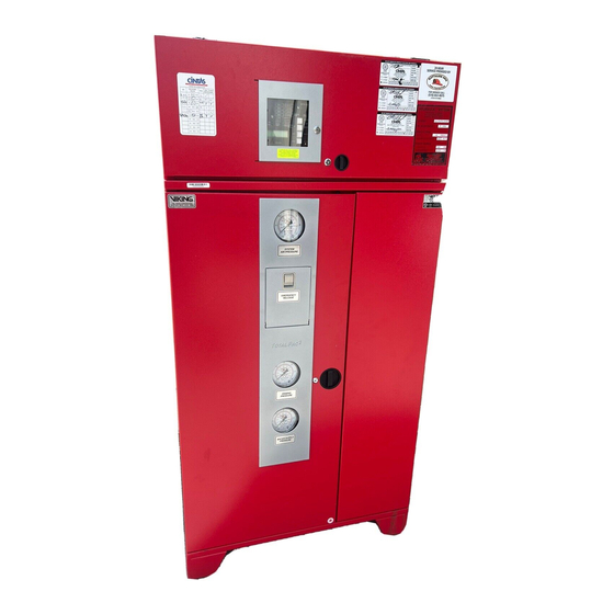
- Page 45 OTAL Page 3 of 8 2 Integrated Fire Protection System OTAL Control Section Figure 1 - Cabinet door assembly: Control section hinged door Releasing panel controls (recessed hinges on top) access door (stainless steel) FM-086V-0-19 Door Lock Control Panel Flush door handle (with key alike keys) annunciator window "TBB"...
- Page 46 OTAL Page 4 of 8 2 Integrated Fire Protection System OTAL Control Section Figure 3 - Detail of VFR-400 Panel control section: Emergency batteries FM-086V-0-21 FM-086G-0-29C...
- Page 47 OTAL Page 5 of 8 2 Integrated Fire Protection System OTAL Control Section Figure 4 - Detail of VFR-400 wiring routing: AC POWER POWER LIMITED CIRCUITS 120 / 220 Vac Power Supply (Control panel only) 24Vdc / Ann. Supervisory / Detection "TBC"...
- Page 48 OTAL Page 6 of 8 2 Integrated Fire Protection System OTAL Control Section This page was intentionally left blank FM-086G-0-29C...
- Page 49 OTAL Page 7 of 8 2 Integrated Fire Protection System OTAL Control Section 2- Control Section without control panel. 2.1 Product Description When the T 2 unit is provided without any control OTAL panel, such as in retrofit applications where the unit is connected and controlled by a central control panel already installed in the building or premises.
- Page 50 OTAL Page 8 of 8 2 Integrated Fire Protection System OTAL Control Section Figure 1: Detail of contractor wiring junction box: TBA Field Wiring Terminal Strip 7/8" & 1 1/4" Knockouts for low voltage field wiring 7/8" & 1 1/4" Knockout for 120/250Vac power feed wiring TBB Field Wiring Terminal Strip...
- Page 51 OTAL Page 1 of 12 2 Integrated Fire Protection System OTAL Deluge System - Programming & Field Wiring Diagram 1- Remote Controlled, Pneumatic Release Operation – Deluge When a fire occurs, at least one pilot head reaches its trip The T 2 Unit without control panel is factory wired for OTAL point.
- Page 52 OTAL Page 2 of 12 2 Integrated Fire Protection System OTAL Deluge System - Programming & Field Wiring Diagram Field wiring diagrams: WATER FLOW WATER FLOW SWITCH LOW PRESSURE PNEUMATIC RELEASE SWITCH LOW AIR PRESSURE MAIN VALVE MAIN VALVE NOTES: SUP'V SWITCH - ALL DEVICES ARE SHOWN IN THEIR NORMAL SUPERVISORY STATE.
- Page 53 OTAL Page 3 of 12 2 Integrated Fire Protection System OTAL Deluge System - Programming & Field Wiring Diagram 2- Remote Controlled, Hydraulic Release Operation – Deluge When a fire occurs, at least one releasing device reaches its The T 2 Unit without control panel is factory wired for OTAL trip point.
- Page 54 OTAL Page 4 of 12 2 Integrated Fire Protection System OTAL Deluge System - Programming & Field Wiring Diagram Field wiring diagrams: WATER FLOW WATER FLOW SWITCH NOTES: - ALL DEVICES ARE SHOWN IN THEIR NORMAL SUPERVISORY STATE. MAIN VALVE MAIN VALVE SUP'V SWITCH - DRY CONTACTS RATINGS:...
- Page 55 OTAL Page 5 of 12 2 Integrated Fire Protection System OTAL Deluge System - Programming & Field Wiring Diagram 3- Remote Controlled, Electric Release Operation – Deluge When the detection system operates, the System Control The T 2 Unit without control panel is factory wired for OTAL Panel activates an alarm and energizes the normally closed the following configuration:...
- Page 56 OTAL Page 6 of 12 2 Integrated Fire Protection System OTAL Deluge System - Programming & Field Wiring Diagram Field wiring diagrams: WATER FLOW WATER FLOW SWITCH NOTES: MAIN VALVE MAIN VALVE - ALL DEVICES ARE SHOWN IN THEIR SUP'V SWITCH NORMAL SUPERVISORY STATE.
- Page 57 This programming makes sure the system will perform as Protection capabilities of the system and/or void required and was factory tested to make sure it meets all Listing/Approval and Warranty. Consult FireFlex requirements. Systems before making any change Pre-configured programs allows field programming for...
- Page 58 OTAL Page 8 of 12 2 Integrated Fire Protection System OTAL Deluge System - Programming & Field Wiring Diagram Program #12 Output and Relay Circuits Activated by Detection Circuits: OUTPUT CIRCUITS RELAY CIRCUITS PROGRAM 12 SINGLE HAZARD CROSS ZONED INPUT CIRCUITS SUPERVISORY ZONE 1 (Valve Tamper) SUPERVISORY ZONE 2 (Air) DETECTION ZONE 1...
- Page 59 OTAL Page 9 of 12 2 Integrated Fire Protection System OTAL Deluge System - Programming & Field Wiring Diagram FIELD WIRING DIAGRAMS An individual branch circuit shall be required for the supply of the control panel power source 5.1K, 1/4W ELR (Typical) AC POWER SUPPLY 120 VAC, 60Hz / 220VAC, 50Hz...
- Page 60 OTAL Page 10 of 12 2 Integrated Fire Protection System OTAL Deluge System - Programming & Field Wiring Diagram FIELD WIRING DIAGRAMS An individual branch circuit shall be required for the supply of the control panel power source AC POWER SUPPLY 120 VAC, 60Hz / 220VAC, 50Hz CIRCUIT IS NON-POWER LIMITED 5.1K, 1/4W...
- Page 61 OTAL Page 11 of 12 2 Integrated Fire Protection System OTAL Deluge System - Programming & Field Wiring Diagram POWER LIMITED 4-WIRES DETECTION CIRCUIT 5.1K Ohms 1/4W 24Vdc 24Vdc UL Listed UL Listed PAM-4 24Vdc 4-Wire 24Vdc 4-Wire Power Supervisory Smoke Detector Smoke Detector Relay (EOL Relay)
- Page 62 OTAL Page 12 of 12 2 Integrated Fire Protection System OTAL Deluge System - Programming & Field Wiring Diagram Remote Annunciator RA-4410-RC The RA-44410-RC remote annunciator is designed to operate with the VFR-400 releasing control panel. There are 34 LED's to indicate a change in panel status.
- Page 63 OTAL Page 1 of 12 2 Integrated Fire Protection System OTAL System design & Dimensional Data 1- Skid mounted Unit The T 2 unit skid is made of sturdy 14 gauge steel, OTAL measuring 36" x 20" x 6" (91,4 x 50,8 x 15,2 cm) for 1½", 2" Shipping weights System Size &...
- Page 64 OTAL Page 2 of 12 2 Integrated Fire Protection System OTAL System design & Dimensional Data Figure 1 – Dimensions - Preaction: System Size 1½" 2" 1½" 2" 36" 46" 20" 4" 8 " 9" 18½" 3½" 6" 2" 34½" 5"...
- Page 65 2¾" 4" 3" 2¾" 4" 4" 2¾" 4" 6" 2¾" 4" FLOOR ANCHORING TEMPLATE Figure 3 – Skid clearance detail TotalPac2 Skid Unit Unit Size Minimum Dimension 1 ½" 60" 152,4 cm 2" 60" 152,4 cm 3" 60" 152,4 cm 4"...
- Page 66 Unit Drain Pipe (dia. = C) Air Gap Water Supply Pipe 4" Min. TotalPac2 Skid Ass'y Drain Pipe (pipe diameter per drain flow calculation) Single Unit Detail Figure 5: Open drain details for multiple units: (see dimensions in table below) 12"...
- Page 67 OTAL Page 5 of 12 2 Integrated Fire Protection System OTAL System design & Dimensional Data 2- Cabinet for Remote Controlled Unit The T 2 unit cabinet is made of sturdy 14 gauge Multiple unit installations are easily achieved by manifolding OTAL steel, measuring 36"...
- Page 68 OTAL Page 6 of 12 2 Integrated Fire Protection System OTAL System design & Dimensional Data Figure 1 – Dimensions: CONTRACTOR WIRING JUNCTION BOX Optional Shut-Off Valve OPTIONAL F.D. CONN. OUTLET (DRILLED ONLY WHEN ORDERED !) DRAIN - SCH.40 GROOVED OUTLET WATER INLET SCH.40 GROOVED OUTLET See Note...
- Page 69 OTAL Page 7 of 12 2 Integrated Fire Protection System OTAL System design & Dimensional Data Figure 2 – Cabinet & doors clearance detail System Configuration Size TotalPac2 Unit 1½" 34½" 41¾" 2" 34" 41¼" Preaction 3" 38⅜" 42⅛" 4"...
- Page 70 OTAL Page 8 of 12 2 Integrated Fire Protection System OTAL System design & Dimensional Data Figure 3: Open drain details for single unit: (see dimensions in table below) TotalPac Shown Without Front Door Unit Drain Pipe (dia. = C) Air Gap Water Supply Pipe 4"...
- Page 71 OTAL Page 9 of 12 2 Integrated Fire Protection System OTAL System design & Dimensional Data 3- Cabinet for Self-Contained Unit The T 2 unit cabinet is made of sturdy 14 gauge Multiple unit installations are easily achieved by manifolding OTAL steel, measuring 36"...
- Page 72 OTAL Page 10 of 12 2 Integrated Fire Protection System OTAL System design & Dimensional Data Figure 1 – Dimensions: 2" MAX. OPTIONAL OPTIONAL F.D. SHUT-OFF VALVE CONN. OUTLET (DRILLED ONLY WHEN ORDERED !) DRAIN - SCH.40 GROOVED OUTLET WATER INLET SCH.40 GROOVED OUTLET See Note Note: Access holes provided on...
- Page 73 54½" "NO DRILL" ZONE 6" Figure 2 – Minimum cabinet & doors clearance detail TotalPac2 Unit Note: Control cabinet shown without front door. Hatch pattern indicates zone that should be avoided when drilling for wiring conduits in enclosure, viewed from the left front corner of the cabinet.
- Page 74 OTAL Page 12 of 12 2 Integrated Fire Protection System OTAL System design & Dimensional Data Figure 5: Open drain details for single unit: (see dimensions in table below) TotalPac Shown Without Front Door Unit Drain Pipe (dia. = C) Air Gap Water Supply Pipe 4"...
- Page 75 2 Integrated Fire Protection OTAL This warranty constitutes the entire warranty given by the System from FireFlex Systems Inc., you got the best Manufacturer to the Customer with respect to the product. technology available… You also got the best people…...
- Page 76 OTAL Page 2 of 2 2 Integrated Fire Protection System OTAL IMITED ARRANTY User Notes FM-086G-0-11B...
Need help?
Do you have a question about the TOTALPAC2 and is the answer not in the manual?
Questions and answers