Table of Contents

Related Manuals for Wallace Perimeter Security SPEEDGATE


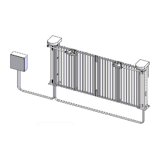
Summary of Contents for Wallace Perimeter Security SPEEDGATE
- Page 1 Revision 1 - MAY 2023 SPEEDGATE INSTALLATION AND MAINTENANCE MANUAL Gen II Models – Pdtt Series & Pdxt-C Series [INTRODUCED 2021] 115 Lowson Crescent Winnipeg, Manitoba, Canada R3P 1A6 Phone: 866.300.1110 wallaceperimetersecurity.com...
- Page 2 This manual has been written with the utmost care and attention. However, the possibility of errors cannot be excluded. Wallace Perimeter Security is not liable for damage arising as a result of errors which occur in the manual. Please inform us immediately of any errors or omissions you may identify.
-
Page 3: Table Of Contents
Entrapment Protection and Pinch Points ������������������������������������������������������ 37 Warning Signs ���������������������������������������������������������������������������������������������� 40 Additional Safety Features ��������������������������������������������������������������������������� 41 Recommended Safety Precautions for the Immediate Vicinity ���������������������42 Safety Instructions for Maintenance ������������������������������������������������������������ 43 SPEEDGATE Installation and Maintenance Manual Revision 1 - MAY 2023... - Page 4 PDXT, PDXT-C and PDTT Electrical Point-to-Point Diagrams - 2 ����������������������61 PDXT, PDXT-C and PDTT Electrical Point-to-Point Diagrams - 3 ����������������������63 Primary & Secondary Operator for a Standard Post Drive Gate SpeedGate ���65 Wire Sizes, Types and Locations ������������������������������������������������������������������� 67 Photo Eye Installation ���������������������������������������������������������������������������������� 70 Photo Eye Alignment �����������������������������������������������������������������������������������...
- Page 5 TABLE OF CONTENTS Troubleshooting ����������������������������������������������������������������� 115 Details on How to Troubleshoot the SpeedGate ����������������������������������������� 115 Operator Fault Codes ��������������������������������������������������������������������������������� 115 Details on How to Operate the Gate ���������������������������������������������������������� 128 Controlled Constant Contact Operation ����������������������������������������������������� 128 Automatic Controlled Momentary Operation ��������������������������������������������� 128 Inspection, Servicing and Maintenance �������������������������������...
-
Page 6: Safety Notices
SAFETY NOTICES SAFETY NOTICES The following four levels of safety notices are used where applicable within this manual; each notice contains information specific to the situation. Common Industrial Symbols Indicates death or serious injury will occur The following international safety symbols may if the hazardous situation is not avoided. -
Page 7: Read This First
Children must never be allowed to play on or around the gate. Wallace Perimeter Security is not liable for damage arising from any manner of use of the SpeedGate. The Wallace Perimeter Security Gate System is applicable to a Class I, Class II, Class III or Class IV Gate System, and may only be installed at locations meeting the UL 325 definitions. -
Page 8: Installation And Commissioning Checklist
Installation and Commissioning Checklist Complete Step Description Manual Section Reference(s) 1. Pallet shipped to site from Wallace Perimeter Security (WPS). page 44 2. Install gate onto concrete anchors; ensure all components level. page 45 (Swing toward property side recommended.) 3. Mount operator cabinet. - Page 9 Manual Section Reference(s) The SpeedGate should only be operated by persons that were onsite for the final gate commissioning. 5.1 CHECK BEFORE POWERING UP THE OPERATOR: 5.1.1 All fasteners for proper tension: 5.1.1-A. Hinge bolts at 85 ft-lbs (115.26 N m) 5.1.1-B.
-
Page 10: Installation And Commissioning Checklist: Setting Gate Limits
INSTALLATION AND COMMISSIONING CHECKLIST Installation and Commissioning Checklist Complete Step Description Manual Section Reference(s) 5.2 Operator Power-up: 5.2.1 Using the manual brake disconnect, move the gate’s panels to page 112 the halfway point between the open and closed position. Clear the gate travel area of all obstructions and apply power to the gate controller. -
Page 11: Installation And Commissioning Checklist: Setting Gate Limits
5.3.2-E. Use the UP and DOWN arrows to scroll to the master password. [4 is the Gate’s Master Password. Call Wallace Perimeter Technical Support at 1 (866) 300-1110 if a password reset is needed.] SPEEDGATE Installation and Maintenance Manual Revision 1 - MAY 2023... - Page 12 STOP button again to return the underscore to the parameter 999 on the left. 5.3.3 STEP THREE: PROGRAMMING THE SPEEDGATE 5.3.3-A. Pull manual brake disconnect cable located inside each column and lock the cable clamp into the groove provided.
- Page 13 210 on the left. 5.3.3-H. Follow the instructions on the LCD display, one operator at a time: 5.3.3-I. Press and HOLD STOP to begin setting the limits. SPEEDGATE Installation and Maintenance Manual Revision 1 - MAY 2023...
- Page 14 INSTALLATION AND COMMISSIONING CHECKLIST: SETTING GATE LIMITS Installation and Commissioning Checklist: Setting Gate Limits Complete Step Description 5.3.3-J. Push the down arrow to CLOSE the gate. If the gate panel OPENS, it means the motor is turning in the WRONG DIRECTION. This PANELS CLOSED: TOP VIEW will require changing the direction of the motor rotation.
- Page 15 P�221, and decrease the value accordingly. accordingly. 100 units/increments = 1 ft (0.3048m) 100 units/increments = 1 ft (0.3048m) Password (P.999 = 4, unless changed) must be entered to access this parameter. SPEEDGATE Installation and Maintenance Manual Revision 1 - MAY 2023...
-
Page 16: Safety Requirements
SpeedGates are made aware of the potential hazards associated with improperly designed, installed, or maintained systems. • Keep in mind that the SpeedGate is a fast-moving bi-fold gate system; entrapment can cause serious injury or death. • Mount access control devices beyond reach of the gate. The control devices that operate the gate must be: ‒... -
Page 17: Safety Considerations For Designers, Installers And Users
Installers, maintenance crews, and owners/users must read and follow the safety Instructions in this manual and review all the literature that accompanies this product. It is important that only qualified installers handle the installation of the SpeedGate gate system. A “qualified” installer has one of the following: ‒... -
Page 18: Safety Standards - Installer's Responsibility
Verify the gate system usage class for the site. Refer to “Application: Identifying Gate System Category and Usage Class” on page 21 for gate classifications. Install SpeedGate only when the gate system class is correct for the site, size, and type of gate. -
Page 19: Important Safeguards And Instructions To Communicate To Owners/Users
The following information is to be explained to the owners and users. • Explain that a SpeedGate will sound an audible alarm for 2 seconds prior to any gate movement, and while the gate is in motion. Additional warning devices, both visual and audible, are available for integration into the gate controller. - Page 20 Although this requires a site-dependent evaluation, typically a distance of 6 feet (1.83 meters) between the controls and any portion of the SpeedGate should be considered as meeting these installation criteria. Outdoor or easily accessible controls shall have a security feature to prevent unauthorized use.
- Page 21 UL 325 definitions. The SpeedGate gate system, according to UL 325 Safety Standards, falls in the Swing Gate and Slide Gate categories for gate systems. Its usage class is determined by the area that the vehicular gate services. Four...
- Page 22 The SpeedGate is not intended for allowing access to pedestrians and/or bicycles. The SpeedGate is commonly used for securing the following: •...
-
Page 23: Introducing Speedgate
Introducing SpeedGate Product Description The SpeedGate is a bi-folding gate that can be opened and closed within a short space of time (less than 8 seconds). The SpeedGate has been designed to allow selective access into a secured area, for security and control purposes. - Page 24 INTRODUCING SPEEDGATE Generally, the SpeedGate consists of five main components, including three categories of safety devices: Table 1. SpeedGate Main Components 1� Columns The columns support the guide channel and the panels. The columns also house all of the drive components for the gate. The columns are anchored to a concrete foundation with anchor bolts.
- Page 25 INTRODUCING SPEEDGATE Table 1. SpeedGate Main Components Additional Optional Sensing Edges • “External Entrapment Protection Safety Devices: Sensors” on page 29 • “External Entrapment Sensor Types” on page 34 • “UL 325 Compliant Sensors” on page Vehicle Detectors • “Additional Safety Features” on page •...
-
Page 26: Safety Devices
Inherent Entrapment Sensor The SpeedGate is equipped with a Type A inherent entrapment sensor (IES) that complies with UL 325 Safety Standards. The IES responds to any impediment to gate travel by causing the gate to stop and reverse. - Page 27 Otherwise, the issue could be with the gate operator or another gate component. ORIGINAL GATE Obstacle Gate Response System Mode POSITION Encountered, Activating the Opening Gate should reverse to closed position and wait for a renewed command. SPEEDGATE Installation and Maintenance Manual Revision 1 - MAY 2023...
- Page 28 SAFETY DEVICES ORIGINAL GATE Obstacle Gate Response System Mode POSITION Encountered, Activating the Opening Gate should reverse to closed position; if it Hard Shutdown Mode encounters an infrared beam (photo eye) input* during reversing=hard shutdown. *or an edge sensor input, if programmed in the same manner as the photo eye Opening Gate should reverse to closed position;...
-
Page 29: External Entrapment Protection Sensors
EXTERNAL ENTRAPMENT PROTECTION SENSORS External Entrapment Protection Sensors The SpeedGate is equipped with a Type A inherent entrapment sensor (IES) which is a reduced speed sensor/torque change sensor, as described in “Inherent Entrapment Sensor” on page 26. The IES is an internal device built into the SpeedGate operator. -
Page 30: Choosing External Entrapment Protection
1. Select the Usage Class according to the gate’s locale and purpose. 2. The required UL 325 inherent Type A sensor is an integral part of the SpeedGate gate system. Based on the gate’s usage class, choose External Type Devices: B1, B2, C, D, or E. -
Page 31: Ul 325 Compliant Sensors
Entrapment protection device types include the inherent reversing sensor system (i.e., Type A), built into the SpeedGate operator, as described in the previous section. To enable fully automatic operation, all bi-fold gate operators will require a minimum of ONE monitored external entrapment protection sensor to protect entrapment zones in either the open or close direction of travel (i.e., 1 for the open direction plus 1 for the close direction). - Page 32 The following sensors have been tested with Wallace Perimeter Security gate operators by an independent laboratory and certified to comply with UL 325 7th Edition. Select sensors from this list for UL compliant gate automation solutions.
- Page 33 UL 325 COMPLIANT SENSORS Figure 2. SpeedGate Common Entrapment Zones SPEEDGATE Installation and Maintenance Manual Revision 1 - MAY 2023...
-
Page 34: External Entrapment Sensor Types
Photo eyes are mounted on the SpeedGate column. If there is a person situated in-between the columns, the light beam of the photo eyes is interrupted and a safety input is activated, preventing the gate from moving. - Page 35 *or an edge sensor input, if programmed in the same manner as the photo eye Gate should reverse to closed position; if it encounters another Opening obstacle during reversing [via the IES (inherent reduced speed sensor/torque change sensor)] = hard shutdown. SPEEDGATE Installation and Maintenance Manual Revision 1 - MAY 2023...
- Page 36 EXTERNAL ENTRAPMENT SENSOR TYPES ORIGINAL GATE Obstacle Gate Response POSITION Detected, Activating Photo Eye Input Closing Gate should reverse to open position and restart the auto close timer. Gate should reverse to open position; if it encounters another Closing infrared beam (photo eye) input* during reversing, another active safety input is triggered.
-
Page 37: Installer And User Safety Considerations
SpeedGate. Safety and Health Hazards The application of the SpeedGate is safe when used according to the stipulations of “Important Safeguards and Instructions to Communicate to Owners/Users” on page 19. The positioning of the SpeedGate in a certain environment will give rise to new risks which will vary from installation to installation. - Page 38 ENTRAPMENT AND PINCH POINTS Safety measures have been taken in the design of the SpeedGate in order to reduce these risks as much as possible. These risks can be limited even further by taking risks into account when positioning the gate and by observing the safety instructions.
- Page 39 Figure 5.5. Qualified Personnel ONLY Figure 5.6. Top View: DANGER! Gate Panels: Collision with the SpeedGate because vehicle attempts to proceed through gate during closing sequence. Figure 5.7. One Vehicle Entry Only per Cycle SPEEDGATE Installation and Maintenance Manual...
-
Page 40: Warning Signs
The hazard warning signs provided with the SpeedGate are mounted immediately adjacent to the SpeedGate on both sides of the opening. Two English language warning signs, and two French language warning signs (both official languages in Canada), are provided with each SpeedGate shipment, for a total of four signs. -
Page 41: Additional Safety Features
“vehicle detection loop” which then becomes an inductive coil. When a vehicle passes over the loop the detector senses the resultant drop in the inductance, and this in turn stops the gate. • The opening and closing force of the SpeedGate is restricted by gate controllers which also regulate the opening and closing times. •... -
Page 42: Recommended Safety Precautions For The Immediate Vicinity
• If there is a wall next to the SpeedGate with a gap of less than 16” (406mm), a gate edge or a photo eye can be mounted on the wall. If someone becomes trapped between the wall and the panel as the Gate opens, the gate edge or the photo eye will be tripped and the SpeedGate will stop. -
Page 43: Safety Instructions For Maintenance
• Place a sign next to the traffic light with the text: “One Vehicle Only per Cycle”. • Adequate lighting can be placed near the SpeedGate to ensure good visibility on both sides of the gate. • A maximum height sign must be indicated on the SpeedGate. A height signaling system can also be installed. -
Page 44: Speedgate Delivery And Unloading
SPEEDGATE DELIVERY AND UNLOADING SpeedGate Delivery and Unloading 1. Once the truck arrives, you will need a forklift 4. Crates are marked with “Open This Side” for with a minimum lifting capacity of 9,240 lbs unpacking. (4191 kg) and 6 ft (2m) long forks (or fork extensions) to unload. -
Page 45: Speedgate Installation
SPEEDGATE INSTALLATION SpeedGate Installation The SpeedGate installation should only be carried out by personnel qualified by Wallace Perimeter Security. REQUIRED FACILITIES: The following facilities must be present at the installation site: • Electricity for the operator cabinet (208 – 240V single phase, 2 hot wires, 1 ground wire). - Page 46 Wallace Perimeter Security for more information. 2. Using a leveling device, check to see that the foundations for the SpeedGate are level with each other. In case of foundations that have been set to different elevations, the anchor bolts will need to be lengthened to accommodate the inconsistency.
- Page 47 A nut and washer shall be tightened on each anchor bolt. STEP 10, 11 8 ¼” is the minimum depth for driving the anchor into the hole. Refer to manufacturer’s instructions for appropriate curing time. SPEEDGATE Installation and Maintenance Manual Revision 1 - MAY 2023...
- Page 48 SPEEDGATE INSTALLATION wallaceperimetersecurity.com Phone: 866.300.1110...
-
Page 49: Gate Installation
Once all bolts are unfastened raise the gate up and place onto the concrete anchors in the concrete foundation. Figure 9. Gate and Lifting Assembly SPEEDGATE Installation and Maintenance Manual Revision 1 - MAY 2023... - Page 50 AWAY from the Secure Side, reverse the location of the hinge mounting holes. As per UL 325 a SpeedGate opening toward the Public Side must have the panels remain over the owner’s property and not move out onto a public sidewalk or street.
- Page 51 PDTT (top track) models. All anchor bolts should be tightened to 210 ft-lbs (284.76 N m). See Figure 11. Figure 11. Securing of Columns SPEEDGATE Installation and Maintenance Manual Revision 1 - MAY 2023...
- Page 52 SPEEDGATE INSTALLATION wallaceperimetersecurity.com Phone: 866.300.1110...
- Page 53 SPEEDGATE INSTALLATION 4. Once all gate components have been assembled and installed, double check all components for level/ square fitting. Using non-shrink grout, fill the area between the SpeedGate column base plates and the concrete foundation. SPEEDGATE Installation and Maintenance Manual...
-
Page 54: Operator Cabinet Installation Considerations
• Mount the Operator Cabinet in a location as near as is practical to the SpeedGate so as to minimize the electrical wiring requirements between the SpeedGate and the Operator Cabinet. -
Page 55: Installation Adjustments
The SpeedGate gate uses a length-adjustable drawbar to align and center the panels. 1. To complete the drawbar adjustment, first ensure the gate is in the fully closed position. To move the gate closed manually, use the manual brake disconnect located under the motor in each column. - Page 56 INSTALLATION ADJUSTMENTS 4. Once adjusted so that the gate panels are square at a 90-degree angle to the roadway, tighten the nuts on either end of the drawbar to lock in the current position. The gate should be installed, all wires terminated properly, and all mechanical adjustments, (including drawbar) made prior to setting the...
-
Page 57: Wiring Installation
Parameter settings and the speed as well as the operation of the safety devices must be checked. • Switching on or operating the controller when condensation is present is not permitted. This can destroy the controller. SPEEDGATE Installation and Maintenance Manual Revision 1 - MAY 2023... - Page 58 WIRING INSTALLATION Turn the controller OFF prior to performing wiring, testing and maintenance work! THEN WAIT. Dangerous voltage levels can commonly remain for 5 minutes. If the switching power supply is defective, voltage discharge times (to fall below 50 VDC) of 10 minutes may occur.
-
Page 59: Pdxt, Pdxt-C And Pdtt Electrical Point-To-Point Diagrams - 1
PDXT, PDXT-C and PDTT Electrical Point-to-Point Diagrams - 1... -
Page 61: Pdxt, Pdxt-C And Pdtt Electrical Point-To-Point Diagrams - 2
PDXT, PDXT-C and PDTT Electrical Point-to-Point Diagrams - 2... -
Page 63: Pdxt, Pdxt-C And Pdtt Electrical Point-To-Point Diagrams - 3
PDXT, PDXT-C and PDTT Electrical Point-to-Point Diagrams - 3... -
Page 65: Primary & Secondary Operator For A Standard Post Drive Gate Speedgate
All gate wiring is provided by Wallace Perimeter Security. All cables are shipped pre-wired at the gate structure. All interconnecting wires between the Primary and Secondary Operators are provided and factory installed by Wallace Perimeter Security. - Page 66 PRIMARY & SECONDARY OPERATOR FOR A STANDARD POST DRIVE GATE SPEEDGATE Single or dual motor applications may be installed, depending upon gate configuration. • If a single folding gate is required, up to 11.5 feet (3.5m)- PDXT Series [or 12 feet (3.66m)- PDTT Series] wide, only two folding gate panels hinged together, one (primary) operator and one column housing one gate motor are required.
-
Page 67: Wire Sizes, Types And Locations
Post the header into the Post Termination box for Termination box for termination. termination. Security access station needs to provide dry contacts for open (N.O.), close (N.O.), stop (N.C.) commands. SPEEDGATE Installation and Maintenance Manual Revision 1 - MAY 2023... - Page 68 WIRE SIZES, TYPES AND LOCATIONS The electrical connections for a SpeedGate are as follows: Table 6. SpeedGate Electrical Connections References Conduit Between Primary and Secondary Columns Run through header between Columns 1 and 2 for PDTT • [PDTT] “PDXT, PDXT-C and (TOP TRACK) Model;...
- Page 69 WIRE SIZES, TYPES AND LOCATIONS Table 6. SpeedGate Electrical Connections References Between the SpeedGate and the Operator Cabinet Motor cables to be kept a minimum of 18 inches (46cm) from the secondary (control) wiring. Multi-Conductor Low Voltage Cable (see 1.1 above) Encoder Cables •...
-
Page 70: Photo Eye Installation
PHOTO EYE INSTALLATION Photo Eye Installation All entrapment safety devices, including photo eyes, must be installed prior to setting the gate limits. The SpeedGate is shipped with one set of through-beam type photo eyes. If a higher safety level is required, the SpeedGate can be equipped with two sets of photo eyes. - Page 71 2. Figure 15 shows the wiring and DIP switch settings of an EMX-MON photo eye (typical through-beam wiring), the type of photo eye normally shipped with a SpeedGate by Wallace Perimeter Security. Receiver DIP Switch Settings...
- Page 72 PHOTO EYE INSTALLATION 3. Typical EMX Photo Eye Connections to Post Termination Connection Board: Table 7. Photo Eye Wiring - One Set Primary Column Bottom Receiver: (+)24, top terminal #6 (-)24, top terminal #10 COM, top terminal #4 NC, top terminal #15 Secondary Column Bottom Transmitter: (+)24, top terminal #2 (-)24, top terminal #9...
-
Page 73: Photo Eye Alignment
The SpeedGate-designated height for bottom-mounted photo eyes is 24” (61cm) above grade and, for the top pair (if included in the installation), 60” (152cm) above grade. Photo eyes are commonly mounted within 5”... - Page 74 If re-alignment or repositioning of transmitter and receiver does not resolve crosstalk and/or the interference is occurring at a site with more than one SpeedGate, decrease the sensitivity setting on the receiver to the position where the green LED on the receiver starts to flash.
-
Page 75: Gate Options
Along with each rubber section there will be an accompanying aluminum channel section of the same length. In a single bi-fold SpeedGate there will be a total of 1 horizontal section. In a double bi-fold gate there will be a total of 2 horizontal sections. - Page 76 GATE OPTIONS Installation of Resistive Gate Edges (8.2 kΩ terminating resistor) Figure 16. Gate Edge Installation Lubricate the edge outer lips with soap and water to allow the rubber edge to slide smoothly into the aluminum channel. When the water dries the edge will no longer slide. There are two cabling formats for resistive edge - a resistive end and a cable end, or both cable ends.
- Page 77 The gate will stop and reverse upon contact with the obstruction. Advise the user of the gate to be certain to retest this vital function weekly. SPEEDGATE Installation and Maintenance Manual Revision 1 - MAY 2023...
-
Page 78: Ul 325 Monitoring Requirement For External Entrapment Protection Devices
Terminal 40 in the SpeedGate operator enclosure terminal strip is designated for monitoring of all external entrapment sensor connections by looking for NC contacts connected to input terminals and cycling the power. - Page 79 UL 325 MONITORING REQUIREMENT FOR EXTERNAL ENTRAPMENT PROTECTION DEVICES SPEEDGATE Installation and Maintenance Manual Revision 1 - MAY 2023...
-
Page 80: Installation Instructions For Optional Vehicle Detectors
INSTALLATION INSTRUCTIONS FOR OPTIONAL VEHICLE DETECTORS Installation Instructions for Optional Vehicle Detectors For SpeedGates using vehicle detectors, they are only to be used for vehicular traffic Vehicle detection ground loop systems, and the loops should not be while not required by UL Standards, less than 60 feet square (5.6 are HIGHLY RECOMMENDED for square meters). - Page 81 Care should be taken to avoid cutting all the way through the pavement material. If possible, the saw cut depth should not exceed one half the thickness of the pavement material. SPEEDGATE Installation and Maintenance Manual Revision 1 - MAY 2023...
- Page 82 INSTALLATION INSTRUCTIONS FOR OPTIONAL VEHICLE DETECTORS Installation of Vehicle Detection Ground-Loop Systems 3.1.3 It is highly recommended that a continuous length of wire be used to form the loop and feeder to the detector. Loop wire is typically 14, 16, 18, or 20 AWG with cross-linked polyethylene insulation which is very resistant to moisture absorption and provides good abrasion resistance.
- Page 83 Channel 1 Loop (which can be configured as an Entrance Loop OR an Exit Loop) typically terminates into terminal #30 and #31. Channel 2 Loop (configuration dependent upon Chanel 1 function) typically terminates into terminal #32 and #33. SPEEDGATE Installation and Maintenance Manual Revision 1 - MAY 2023...
- Page 84 INSTALLATION INSTRUCTIONS FOR OPTIONAL VEHICLE DETECTORS Installation of Vehicle Detection Ground-Loop Systems 8. If an automatic exit loop is required, a third detector relay will be required. If an automatic exit loop is required, a third detector relay will be required (not supplied by Wallace Perimeter Security).
-
Page 85: Optional Gate Status Proximity Sensors And Mounting Plates
7 feet (2.13m). The wiring must be pulled to the post termination box. Holes for wiring must be drilled after mounting location has been determined. The wiring passes through the bottom of the base plate. SPEEDGATE Installation and Maintenance Manual Revision 1 - MAY 2023... -
Page 86: Electrical Circuits
ELECTRICAL CIRCUITS ELECTRICAL CIRCUITS Post Termination Box All the gate safety inputs except for the vehicle detector loop leads terminate into the post termination box. The multi-conductor low voltage cable connects the post termination box to the Operator Cabinet. All wires from the secondary column terminate into the post termination box, located in the primary column. - Page 87 Secondary Column Bottom Transmitter: (+)24, top terminal #2 (-)24, top terminal #9 Always refer to site-specific drawings issued for the project you are working on for actual electrical connections and installation methods. SPEEDGATE Installation and Maintenance Manual Revision 1 - MAY 2023...
- Page 88 ELECTRICAL CIRCUITS 2. MOTOR BRAKES - MANDATORY Each column motor has a 24VDC brake which must be disengaged to allow motor operation. The brake is mechanically engaged and must have power to disengage. Typical (example-only; see bolded text) motor brake connections to the post termination box are: PRIMARY COLUMN MOTOR BRAKE: Uses terminals (+) 25 &...
- Page 89 Always refer to site-specific drawings issued for the project you are working on for actual electrical connections and installation methods. SPEEDGATE Installation and Maintenance Manual Revision 1 - MAY 2023...
- Page 90 ELECTRICAL CIRCUITS 4. STROBE WARNING DEVICE – OPTIONAL This output allows connections for a 24VDC strobe light to be used as a pre-warning to gate movement. Typical (example-only; see bolded text) strobe connections to the post termination box are: STROBE LIGHT: Uses terminals (-) 14 &...
- Page 91 This output allows for a red and green traffic light as an additional precautionary device. This will permit greater control over the vehicle movements in and around the SpeedGate. Typical (example-only; see bolded text) traffic light connections to the post termination box are:...
-
Page 92: Electrical Circuit - Operator
ELECTRICAL CIRCUIT – OPERATOR Electrical Circuit – OPERATOR 1. ANY OPEN DEVICE Any device used to open the gate, such as a pushbutton, key switch or access system typically connects to terminal #3 and #6 in the primary operator. 2. ANY CLOSE DEVICE Any device used to close the gate, such as a pushbutton, key switch or access system typically connects to terminal #4 in the primary operator. - Page 93 ELECTRICAL CIRCUIT – OPERATOR 4. EXTERNAL STOP DEVICE Always refer to site-specific drawings issued for the project you are working on for actual electrical connections and installation methods. SPEEDGATE Installation and Maintenance Manual Revision 1 - MAY 2023...
- Page 94 ELECTRICAL CIRCUIT – OPERATOR 5. ENCODERS Each motor, which is housed in each column, has an encoder. The encoder is used to track the motor’s position and to ensure accurate torque monitoring. The primary column’s encoder typically terminates into the Primary Operator terminals White wire/Blue ferrule - #9, Orange wire/White ferrule- #10, Blue wire/White ferrule - #11, White wire/Orange ferrule- #12 and the encoder ground into #13.
- Page 95 5. ENCODERS Primary Operator Secondary Operator Primary Operator Secondary Operator Always refer to site-specific drawings issued for the project you are working on for actual electrical connections and installation methods. SPEEDGATE Installation and Maintenance Manual Revision 1 - MAY 2023...
- Page 96 ELECTRICAL CIRCUIT – OPERATOR 5. ENCODERS Figure 22. Motor Encoder Location Always refer to site-specific drawings issued for the project you are working on for actual electrical connections and installation methods. wallaceperimetersecurity.com Phone: 866.300.1110...
- Page 97 6. INTERLOCK Expansion board RFUxFCOM (or other authorized communication devices) can be plugged into the RS485 interface for communication between primary and secondary controllers on a single gate. Primary Operator SPEEDGATE Installation and Maintenance Manual Revision 1 - MAY 2023...
- Page 98 ELECTRICAL CIRCUIT – OPERATOR 6. INTERLOCK Secondary Operator Always refer to site-specific drawings issued for the project you are working on for actual electrical connections and installation methods. wallaceperimetersecurity.com Phone: 866.300.1110...
- Page 99 208-240V. This option can be specified when the SpeedGate is ordered. A typical Wallace Perimeter Security shop installation for a FEIG Gen II (SpeedGate model introduced in 2021) is wired as indicated below. This configuration allows the heater to remain ON as long as incoming power is present.
- Page 100 Perimeter Security). This auxiliary detector should be powered from terminals #1 and #2 and wired as a N.O. contact to terminals #1 and #3. Call Wallace Perimeter Security Technical Support at 1 (866) 300-1110 for assistance, if required. Always refer to site-specific drawings issued for the project you are working on for actual electrical connections and installation methods.
-
Page 101: Pdxt-C Or Pdtt-Max Sample Wiring Diagrams
PDXT-C OR PDTT-MAX SAMPLE WIRING DIAGRAMS PDXT-C or PDTT-Max Sample Wiring Diagrams SPEEDGATE Installation and Maintenance Manual Revision 1 - MAY 2023... -
Page 112: Manual Operation Using The Brake Disconnect Cable
MANUAL OPERATION USING THE BRAKE DISCONNECT CABLE Manual Operation Using the Brake Disconnect Cable To manually move the SpeedGate by hand follow the instructions below. Before beginning the procedure ensure: • You have the access door keys and operator keys. - Page 113 7. In one column pull down on the cable and activation method to return gate to normal remove it from the groove. It should now operation. be free hanging which re-engages the brake. Repeat for the other column. SPEEDGATE Installation and Maintenance Manual Revision 1 - MAY 2023...
-
Page 114: Gate Settings: Obstacle Detection
Gate Settings: Obstacle Detection Setting the Reduced Speed Sensor/Torque Change Sensor The SpeedGate Inherent Entrapment Sensor (IES) will consist of a Reduced Speed Sensor/Torque Change Sensor, the absolute encoder located under the brake disconnect switch in each column. The IES senses the position of the gate for gate operation and reduced speed sensing when the gate has come into contact with an obstruction. -
Page 115: Troubleshooting
#1. These terminals are normally jumped. Ensure that the jumper is seated properly in both terminals. This error would be tripped by the brake disconnect switch on FEIG Gen II (i.e., SpeedGate models introduced in 2021). SPEEDGATE Installation and Maintenance Manual Revision 1 - MAY 2023... - Page 116 ‒ There is a short in the wire. This error would be tripped by the brake disconnect switch on FEIG Gen I (i.e., SpeedGate models introduced prior to 2021). F�369 Sensing Edge Fault Either there is an obstruction tripping the sensing edge or the operator was not parameterized properly.
- Page 117 Close Input 3 Loop Safety Input Stop Input 9 Loop Close Input Close Input 10 Inputs on the Operator (for SpeedGate models introduced PRIOR to 2021 - FEIG Gen I) Input FEIG I Terminal(s) LCD Display External Stop 1 1 & 2 F.211 External Stop 1 tripped...
- Page 118 TROUBLESHOOTING Improper End Positions Error Description Cause F�000 Gate position too far ‒ Too small a parameter value for upper emergency open. limit switch. Value of parameter P�233 (limit switch band) too ‒ small. ‒ Mechanical adjustments potentially required. F.005 Gate position too far ‒...
- Page 119 ‒ Controller board defective. F�363 Interruption on edge input. ‒ Connection cable defective or not connected. ‒ Termination resistor incorrect or missing. ‒ Jumper J600 incorrectly set. SPEEDGATE Installation and Maintenance Manual Revision 1 - MAY 2023...
- Page 120 TROUBLESHOOTING Safety Circuit Faults Error Description Cause F�364 Safety edge testing failed. ‒ Safety edge was not activated as expected when requesting a test. ‒ The time between request for testing and actual testing not synchronized. F.365 Redundancy error with ‒...
- Page 121 Ambient temperature too low for controller operation. ‒ Clock frequency of final stage too high (Parameter P�160). F�440 Over-current in ‒ Boost not adjusted. intermediate circuit Limit 1. ‒ Gate sticks. SPEEDGATE Installation and Maintenance Manual Revision 1 - MAY 2023...
- Page 122 TROUBLESHOOTING General Hardware Faults Error Description Cause F.510 Wrong motor data set (P.100 – P.103). Motor / intermediate ‒ circuit over-current Limit 2. ‒ Non-adjusted voltage increase / boost set (P.140 or P.145). ‒ Gate sticks. F.515 Motor protection function ‒...
- Page 123 (also F�031 rotation error). F.750 Protocol Transmission error. Defective hardware or electrically noisy environment. F.751 Synchronization <-> ‒ Defective hardware electrically noisy absolute encoder. environment. ‒ Absolute encoder processor electronics defective. SPEEDGATE Installation and Maintenance Manual Revision 1 - MAY 2023...
- Page 124 (EMI) from other sources. The recommended solution to this problem is to apply EMI shielding. SpeedGate factory installations that occurred after March 2023 may already include electromagnetic interference shielding (Ferrite EMI Cable Core - Laird Part Number LFB259128-000), available through Wallace Perimeter Security.
- Page 125 TROUBLESHOOTING The following ferrite EMI cable core installation instructions are provided for informational purposes only. Consult Wallace Perimeter Security for installation requirements relevant to your project. 1. Unplug cable, located in the operator enclosure, connecting the primary and secondary controller COM boards.
- Page 126 TROUBLESHOOTING Internal System Faults Error Description Cause F.915 Communication error Hardware defect. between main board processor and I/O processor. F�920 Internal 2.5 V reference Hardware defect. voltage incorrect. F�921 Internal 15 V voltage Hardware defect. incorrect. F�922 External Stop circuit not ‒...
- Page 127 Program version / ‒ New EPROM version. manufacturer code. ‒ Controller not yet initialized. F�970 Parameter block error. ‒ New EPROM version. ‒ Controller not yet initialized. ‒ Some parameter is invalid. SPEEDGATE Installation and Maintenance Manual Revision 1 - MAY 2023...
-
Page 128: Details On How To Operate The Gate
DETAILS ON HOW TO OPERATE THE GATE Details on How to Operate the Gate Following a Hard Shutdown, and prior to resetting the system, it is the sole responsibility of the user to ensure the area is free of obstructions and that it is safe to operate the Gate. Refer to “Table 2. Inherent Entrapment Sensor (IES) Shutdown Modes”... -
Page 129: Inspection, Servicing And Maintenance
Alterations to the SpeedGate which could have a negative effect on the safety of the SpeedGate are not permitted. The SpeedGate owner is responsible to ensure that all personnel have received, read and signed the instructions found in “End User Briefing Instructions” on page 137. Personnel that have received the end-user briefing are qualified to perform SpeedGate cleaning and maintenance. -
Page 130: Periodic Maintenance To The Entire Installation: Weekly, Quarterly, Semi-An- Nually, General (Repair And Additional)
Periodic Maintenance to the Entire Installation: Weekly, Quarterly, Semi-Annually, General (Repair and Additional) Maintenance is essential in order to guarantee the safety and the satisfactory operation of the SpeedGate. Maintenance checks should be conducted only by qualified maintenance personnel. The following maintenance interval checklists are provided to record repair requirements, maintenance performed and additional observations pertinent to the SpeedGate. -
Page 131: Speedgate Quarterly Control Maintenance Checklist
SPEEDGATE QUARTERLY CONTROL MAINTENANCE CHECKLIST 1-SPEEDGATE WEEKLY MAINTENANCE CHECKLIST Checked Good Needs Attention 5. Clean photo eyes (external entrapment protection sensors) with a soft, clean, dry cloth and ensure they are in good working order. 6� If used in particular application:... -
Page 132: Speedgate Quarterly Gate Drive System Maintenance Checklist
Attention SpeedGate Serial Number: All drive mechanism maintenance activities must be carried out by maintenance personnel or personnel pre-approved by Wallace Perimeter Security and recorded in an equipment maintenance logbook. 1. Perform a general visual inspection. 2. Remove covers. 3. Grease drive linkage rod end bearing with lithium... -
Page 133: Speedgate Semi-Annual Maintenance Checklist
SPEEDGATE SEMI-ANNUAL MAINTENANCE CHECKLIST 3-SPEEDGATE QUARTERLY (EVERY THREE MONTHS) Checked Good Needs GATE DRIVE SYSTEM MAINTENANCE CHECKLIST Attention 5. Check torque on motor bolts (105 ft-lbs) (142.36 N m). 6. Check torque on motor mount plate (105 ft-lbs) (142.36 N m). - Page 134 SPEEDGATE SEMI-ANNUAL MAINTENANCE CHECKLIST 4-SPEEDGATE SEMI-ANNUAL (EVERY SIX MONTHS) Checked Good Needs MAINTENANCE CHECKLIST Attention 2. Lubricate all revolving parts (every 10,000 cycles or six months). Recommended gate hinge lubricant: Castrol Pyroplex® Protection ES, a synthetic lithium complex grease. Grease the gate hinge opening leading to the pin on the top and on the bottom, using a grease gun.
-
Page 135: Speedgate General Maintenance Checklist
Attention SpeedGate Serial Number: The following checklist is intended to record repair requirements, maintenance performed and additional observations pertinent to the SpeedGate. Checklists must be dated, signed and retained for record- keeping purposes. 1. Physical structure - no damage. 2. Secure hinge bolts - (90 ft-lbs) (122.03 N m) torque. - Page 136 SPEEDGATE GENERAL MAINTENANCE CHECKLIST 5-SPEEDGATE GENERAL MAINTENANCE CHECKLIST Checked Good Needs Attention 9. Accessory devices secure in cabinet (loop relays, etc). 10. Auto-close timer, interlock functional (if enabled). 11. Cabinet thermal cover installed correctly (if equipped). 12. Center catch shoe functional/secure (if installed).
-
Page 137: End User Briefing Instructions
READ AND FOLLOW ALL OF THESE INSTRUCTIONS. 1. Ensure the installer of the SpeedGate has provided the End User with a complete review, demonstration thereof, and supporting documentation of the following: a. A complete copy of the Installation Manual, which will include mechanical and electrical drawings and instructions for the proper operation and service of the gate system. - Page 138 8. The Gate System is for vehicles only. Pedestrians must use a separate gate. 9. SAVE THESE INSTRUCTIONS. Installer’s (OR SpeedGate Owner) Name Printed: End User’s Name (Printed): Installer’s (OR SpeedGate Owner) Signature: End User’s Signature:...
-
Page 139: Speedgate
SPEEDGATE 2 YEAR LIMITED PRODUCT WARRANTY For a period of 2 Years from date of delivery, Wallace Perimeter Security (“WPS”) warrants the product delivered to Buyer as follows: (1) the hardware shall be free from defects in material and workmanship and will conform to the applicable WPS specification and the terms of this proposal, and (2) the software and firmware will conform to the applicable WPS specifications and the terms of use. -
Page 140: Technical Specifications
TECHNICAL SPECIFICATIONS TECHNICAL SPECIFICATIONS PDTT PDXT Technical Data: Series Specifications Technical Data: Series Specifications MAX Height 14 ft (4.27 m) MAX Height 10 ft (3.05 m) MAX Width 24 ft (7.31 m) MAX Width 18 ft (5.49 m); 23 ft (7.01 m) for heights Opening Speed 8 seconds <... - Page 142 115 Lowson Crescent Winnipeg, Manitoba, Canada R3P 1A6 Phone: 866.300.1110 wallaceperimetersecurity.com...
Need help?
Do you have a question about the SPEEDGATE and is the answer not in the manual?
Questions and answers
How to download latest faulty code list by fold gate