
Related Manuals for Wallace Perimeter Security FOLDSMART


Summary of Contents for Wallace Perimeter Security FOLDSMART
- Page 1 Revision 1 - MAY 2023 FOLDSMART™ INSTALLATION AND MAINTENANCE MANUAL 115 Lowson Crescent Winnipeg, Manitoba, Canada R3P 1A6 Phone: 866.300.1110 wallaceperimetersecurity.com...
- Page 2 Copyright Notice ©Copyright 2023 all rights reserved. No part of this manual may be reproduced by any means (photocopier, electronic, or mechanical), without the express written permission of Wallace Perimeter Security and Nice | HySecurity Gate Inc. wallaceperimetersecurity.com Phone: 866.300.1110...
-
Page 3: Table Of Contents
UL 325 Compliant Sensors ��������������������������������������������������������������������������� 20 Stop Button ������������������������������������������������������������������������������������������������� 22 Manual Release ������������������������������������������������������������������������������������������� 22 Wind Load Factors & Site Prep ��������������������������������������������������������������������� 23 FoldSmart Gate Delivery and Unloading ������������������������������� 24 Tools Required ��������������������������������������������������������������������������������������������� 26 FoldSmart Gate Installation �������������������������������������������������� 29 Footing and Foundation Installation ������������������������������������������������������������ 29 Gate Installation ������������������������������������������������������������������������������������������... - Page 4 TABLE OF CONTENTS Manual Release Procedure �������������������������������������������������������������������������� 43 Power ����������������������������������������������������������������������������������� 44 Installing the Earth Ground �������������������������������������������������������������������������� 44 Wiring AC Power ������������������������������������������������������������������������������������������ 46 Wiring 115VAC Power ���������������������������������������������������������������������������������� 47 Wiring 208/230VAC Power ��������������������������������������������������������������������������� 48 Connecting DC Power ���������������������������������������������������������������������������������� 50 Important Considerations for DC-Power Connection ������������������������������������50 Display and Menu Options ���������������������������������������������������...
- Page 5 Vehicle Detector and Loop Fault Diagnostics ���������������������������������������������� 134 General Maintenance ��������������������������������������������������������� 138 Smart Touch Analyze and Retrieve Tool (S.T.A.R.T.) ������������������������������������� 138 Electrical Controls �������������������������������������������������������������������������������������� 140 Mechanical Maintenance ��������������������������������������������������������������������������� 140 Software Maintenance ������������������������������������������������������������������������������ 141 FoldSmart™ Installation and Maintenance Manual Revision 1 - MAY 2023...
- Page 6 DC Battery Replacement ���������������������������������������������������������������������������� 142 Clock Battery Replacement ������������������������������������������������������������������������ 143 FoldSmart General Maintenance Checklist �������������������������� 144 FoldSmart XT Drawings: Generic Site Layout and Options �� 147 FOLDSMART ���������������������������������������������������������������������������������������������� 159 3 YEAR LIMITED PRODUCT WARRANTY ������������������������������������������������������ 159 Technical Specifications ����������������������������������������������������������������������������� 161 wallaceperimetersecurity.com...
-
Page 7: Introducing Foldsmart
600:1 gearbox providing variable speeds. The electronics, motor and gear box are rated to operate in very broad temperatures that range from -13°F to 158°F (-25°C to 70°C). FoldSmart is rated for gates up to 30 feet wide and 6 feet high (9.14 meters wide and 1.8 meters high). -
Page 8: Technical Support
TECHNICAL SUPPORT Technical Support For technical support, call Wallace Perimeter Security at 1-866-300-1110. Obtain the serial number of your operator before calling. Refer to the blow-apart image on the inside of the front page. For information about Wallace Perimeter Security training for installers, maintenance personnel and end- users, refer to the company website at www.wallaceperimetersecurity.com... -
Page 9: Installer's Check List
INSTALLER’S CHECK LIST Installer’s Check List The following list provides a high-level overview of the tasks involved in installing the FoldSmart gate system. Take a moment to review the list and check off the items as you complete the install. -
Page 10: Safety Information
SAFETY INFORMATION SAFETY INFORMATION Safety Notices The following four levels of safety notices are used where applicable within this manual; each notice contains information specific to the situation. Common Industrial Symbols Indicates death or serious injury will occur The following international safety symbols may if the hazardous situation is not avoided. -
Page 11: Safety Requirements
Installers, maintenance crews, and owners/users must read and follow the Important Safety Instructions in this manual and review all the literature that accompanies the product. It is important that only qualified installer’s handle the installation of the FoldSmart gate system. A “qualified” installer has one of the following: •... -
Page 12: Safety Standards - Installer's Responsibility
Verify the gate system usage class for the site. Refer to “Identifying Gate System Category and Usage Class” on page 18 for gate classifications. Install FoldSmart only when the gate system class is correct for the site, size, and type of gate. - Page 13 • Test the red Stop Button located on the side of the control box. Gate system instructions must be given to the owner per UL 325 Safety Standards. FoldSmart™ Installation and Maintenance Manual Revision 1 - MAY 2023...
-
Page 14: Safety Standards - Owner/User Responsibility
SAFETY STANDARDS - OWNER/USER RESPONSIBILITY Safety Standards - Owner/User Responsibility Before attempting a manual release, A moving gate can cause serious make sure the gate is not moving. injury or death. Automatic gate systems move gates with high force. Make sure gates and gate •... -
Page 15: Hazardous Materials And Proper Disposal
HAZARDOUS MATERIALS AND PROPER DISPOSAL Hazardous Materials and Proper Disposal FoldSmart uses sealed, state-of-the-art Absorbed Glass Mat (AGM) batteries and highly recommends replacing used batteries with new AGM-type batteries. batteries used with FoldSmart gate contain materials that are considered hazardous to the environment. -
Page 16: External Entrapment Protection Sensors
EXTERNAL ENTRAPMENT PROTECTION SENSORS External Entrapment Protection Sensors FoldSmart is equipped with a Type A inherent entrapment sensor (IES). UL 325 Safety Standard compliance requires installation of external entrapment protection sensors, the number of which, depends on the entrapment hazards that exist at each particular installation. - Page 17 Refer to the UL website at https://www.ul.com/ for the most up- to-date list of gate system safety standards (UL 325). Refer to https://www.astm.org/ for a complete list of ASTM F2200 Gate and Fence Standards. FoldSmart™ Installation and Maintenance Manual Revision 1 - MAY 2023...
-
Page 18: Identifying Gate System Category And Usage Class
Identifying Gate System Category and Usage Class The FoldSmart gate system, according to UL 325 Safety Standards, falls in the Swing Gate and Slide Gate category for gate systems. Its usage class is determined by the area that the vehicular gate services. Four... -
Page 19: Choosing External Entrapment Protection
The site designer or installer must determine which external entrapment sensor devices will be installed with the FoldSmart operator to meet UL compliance. The type(s) of entrapment sensor device systems are described below. For a complete listing of the requirements, see UL 325 Safety Standards. -
Page 20: Ul 325 Compliant Sensors
AC power. Recommended External Entrapment Protection Sensors List for FoldSmart Mfg. Part # or Model Brand Wallace Perimeter Max. Range... - Page 21 UL 325 COMPLIANT SENSORS Recommended External Entrapment Protection Sensors List for FoldSmart Excerpts from UL 325 Standard: The operator shall monitor for the presence of every device at least once during each open and close cycle. (Clause 32.1.8 of the Standard)
-
Page 22: Stop Button
Manual Release Make sure to teach all users how to turn off electric power and how to move the gate manually. FoldSmart allows a gate to be pushed manually if the quick disconnect bolt is removed from the actuator arm. It is recommended that you turn off DC power which disengages the motor allowing you to easily move the gate. -
Page 23: Wind Load Factors & Site Prep
If the gate is heavy and near the weight capacity of what the gate system can handle (see specifications for FoldSmart on the back cover), make sure it has an open design that allows wind to flow through it. A solid or semi-solid gate design under certain wind load conditions may cause damage to the gate system and is not covered by the Wallace Perimeter Security Limited Warranty. -
Page 24: Foldsmart Gate Delivery And Unloading
FOLDSMART GATE DELIVERY AND UNLOADING FoldSmart Gate Delivery and Unloading 1. Once the truck arrives, you will need a forklift 4. Take care when lifting. with a minimum lifting capacity of 5,000lbs (2,268 kg) and 6 ft (2m) long forks (or fork extensions) to unload. - Page 25 • Two motor and gearbox containers • Two (primary & secondary) operator containers NOTE: Due to its modular construction design, the FoldSmart Gate may be shipped differently than described herein. FoldSmart™ Installation and Maintenance Manual Revision 1 - MAY 2023...
-
Page 26: Tools Required
Shop Vacuum 3/4" round steel brush, air pump (not bulb type) Holes in Concrete Rotating Laser Level Leveling Anchors FoldSmart Gate Installation: Telescopic boom forklift or equivalent with a reach capacity of at least Lifting Gate/Parts 4' above gate structure... - Page 27 1/2" Corded Drill with 1/4", 3/8", and 1/2" Cobalt Drill Bits Steel 1/4" Multi-Drive Screwdriver Gate Fasteners Measuring tapes, wire cutters/strippers, utility knife, permanent Miscellaneous marker, multi-meter Pail/mixing wand/trowel, for grouting beneath flange mount plates Gate Columns FoldSmart™ Installation and Maintenance Manual Revision 1 - MAY 2023...
- Page 28 TOOLS REQUIRED Included T-27 Security Driver Bit Penta Key 3/8” Ball Nose T-Handle (if applicable) For use with 1/2-inch socket. Driver (Socket not supplied with gate.) Fasteners 1/2” Nut 1/4” x 3/4” SS T27 1/4” SS Flat Washer 1/2” Flat Washer Anchor Plate 1/4”...
-
Page 29: Foldsmart Gate Installation
The greater the angle, the lower the drawing strength of the hoisting straps. (Consult the strap manufacturer for more information). During installation, avoid damage to the coating layer of the FoldSmart Gate if it is powder-coated. The following step-by-step instructions for the installation and connection of the FoldSmart Gate should be followed. - Page 30 3. Place each steel anchor bolt template on the prepared foundations making sure that templates are aligned and centered on the foundations. If the FoldSmart Gate is being installed near a wall, object or pre-existing opening make sure that each side of the template is the same distance from the wall, object or pre-existing opening.
- Page 31 A nut and washer shall be tightened on each anchor bolt. STEP 10, 11 8-1/4” (21cm) is the minimum depth for driving the anchor into the hole. Refer to manufacturer’s instructions for appropriate curing time. FoldSmart™ Installation and Maintenance Manual Revision 1 - MAY 2023...
- Page 32 FOLDSMART GATE INSTALLATION 90o to Roadway x2 / Pile 1/2” x 2-3/4” Deep x2 / Pile Concrete Template Anchor x4 / Pile Gate Anchor x4 / Pile See Manufacturer’s 7/8” by 9” deep recommendation for adhesive cure time x4 / Pile...
-
Page 33: Gate Installation
AWAY from the Secure Side, reverse the location of the hinge mounting holes. As per UL 325 a FoldSmart Gate opening toward the Public Side must have the panels remain over the owner’s property and not move out onto a public sidewalk or street. - Page 34 FOLDSMART GATE INSTALLATION 3. Secure both columns using nuts/washers. Securing of Columns wallaceperimetersecurity.com Phone: 866.300.1110...
- Page 35 FOLDSMART GATE INSTALLATION FoldSmart™ Installation and Maintenance Manual Revision 1 - MAY 2023...
- Page 36 FOLDSMART GATE INSTALLATION wallaceperimetersecurity.com Phone: 866.300.1110...
- Page 37 FOLDSMART GATE INSTALLATION FoldSmart™ Installation and Maintenance Manual Revision 1 - MAY 2023...
- Page 38 FOLDSMART GATE INSTALLATION wallaceperimetersecurity.com Phone: 866.300.1110...
-
Page 39: Operator Cabinet Installation Considerations
The operator enclosure has to be located within 10 feet (3.05 meters) of the motor. • Mount the Operator Cabinet in a location as near as is practical to the FoldSmart gate so as to minimize the electrical wiring requirements between the FoldSmart and the Operator Cabinet. -
Page 40: Installation Adjustments
INSTALLATION ADJUSTMENTS Installation Adjustments Drawbar Adjustment Procedure The FoldSmart gate uses a length-adjustable drawbar to align and center the panels. 1. This adjustment is to be done in conjunction with limit setting via the limit switches. Before completing the drawbar adjustment, 4. -
Page 41: Limit Switch Adjustment Procedure
Limit Switch Adjustment Procedure 5. Once adjusted so that the gate panels are The FoldSmart gate uses limit switches to identify square at a 90-degree angle to the roadway, the open and closed positions. The open and tighten the nuts on either end of the drawbar closed positions can be modified by adjusting the to lock in the current position. - Page 42 INSTALLATION ADJUSTMENTS 3. Once the covers are removed, identify the open and closed limit switches. The limit switch furthest from the gate panels is always the closed limit switch, no matter the handing of the gate. 7. When adjusting the cam(s), a small amount of adjustment will result in a much larger 4.
-
Page 43: Manual Release Procedure
The gate owner will be able to provide the storage location of the Penta key. We recommend keeping it in one of the FoldSmart control cabinets for quick access in the event of an emergency. The key can be used with a 1/2-inch socket. -
Page 44: Power
Wallace Perimeter Security recommends grounding the operator with a separate earth ground connected to a ground rod to assure proper operation and shield it against electromagnetism and other electrical signals that may cause erratic operation with or damage to the SmartDC Controller. - Page 45 Properly grounding the gate system is critical to gate system performance and the life of its electrical components. Use sufficient wire size during installation. Refer to “Wiring 115VAC Power” on page 47 or “Wiring 208/230VAC Power” on page 48. FoldSmart™ Installation and Maintenance Manual Revision 1 - MAY 2023...
-
Page 46: Wiring Ac Power
See Figure 2. The voltage selector and AC power switches, on the side of switch on the AC Power board must be the FoldSmart control box, are in the moved to the 230V position or damage off position. See Figure 2. -
Page 47: Wiring 115Vac Power
Verify AC power supply wires and low voltage (12V & 24V accessory power wires) run through two separate conduits. The higher voltage from the AC power supply may cause interference and anomalies in FoldSmart operation if the high and low voltage wires are routed through the same conduit. -
Page 48: Wiring 208/230Vac Power
WIRING 208/230VAC POWER Wiring 208/230VAC Power All FoldSmart operators are shipped from the factory as 115VAC units. When connecting to 208/230VAC power, the voltage selector switch on the AC power board must be moved to the 230V position or damage to the operator will occur and void the Limited Warranty. - Page 49 7� Neatly organize all wire connections and replace the high voltage junction box cover. Secure it with the two Phillips-head screws. 8� Place the 208V or 230V 1Ø label on the Junction Box Cover over the 115V 1Ø label. FoldSmart™ Installation and Maintenance Manual Revision 1 - MAY 2023...
-
Page 50: Connecting Dc Power
• Wallace Perimeter Security uses a permanently sealed AGM-type battery which lasts much longer than wet cell batteries and needs no maintenance over its life span. Batteries are protected from over discharge by a low voltage sensing circuit. The charger circuit regulates to allow high charger output when the battery is partially discharged. -
Page 51: Display And Menu Options
Installer Menu charts provide information about peripheral connections and the corresponding menu items that need to be configured. INITIAL SETUP Once you’ve completed the installation of the FoldSmart operator and attached the wired accessories, you’re ready to program the operator. Two different approaches exist: Method 1:... -
Page 52: Turning Both Power Switches On
TURNING BOTH POWER SWITCHES ON Turning Both Power Switches On One AC and one DC rocker power switch are located on the outside edge of the control box. Refer to Figure 4. 1� Turn both power switches ON. An audible beep occurs and a red light pulsates next to the OPEN button on the SmartDC Controller which indicates the system is functioning. - Page 53 Red - the operator has experienced an error. Figure 5. Controller Indicator Lights • Not lit - AC power is lost. Pressing the SHOW LEDs button indicates which inputs, if any, are active. FoldSmart™ Installation and Maintenance Manual Revision 1 - MAY 2023...
-
Page 54: Using The Smartdc Controller Buttons In Menu Mode
USING THE SMARTDC CONTROLLER BUTTONS IN MENU MODE Using the SmartDC Controller Buttons in Menu Mode The buttons on the SmartDC Controller let you navigate, change, or clear the information in the display menus. Refer to Figure 6. The buttons with text above and below are variable function keys (VFK). Use these buttons to enter or change operational data and navigate through the User and Installer Menus. -
Page 55: Configuring The Setup Menu
Four sequential displays present information 0 – No Handing set. Gate will not move until handing is set. which must be configured before FoldSmart will R – Right-hand gate opening. function. Once the configuration is complete, the Looking at the gate from the... -
Page 56: Run Mode
RUN MODE RUN MODE Gate status displays appear when the operator is ready and waiting for a gate operation command. When the menu display is flashing “GATE OPENING” or “GATE CLOSING” a command has been received and the operator is responding appropriately. The command may come from a variety of sources: a card reader, push-button remote, or recognition of a vehicle passing over a loop detector. -
Page 57: Using The Smartdc Controller Buttons In Run Mode
STOP button while more serious faults require the RESET button or cycling power, and then pressing RESET. Faults indicate a need for diagnosis and resolution. Refer to “SmartDC Controller Troubleshooting” on page 122� Figure 9. Function of SmartDC Controller Buttons in Run Mode FoldSmart™ Installation and Maintenance Manual Revision 1 - MAY 2023... -
Page 58: Viewing Operator Status Displays
VIEWING OPERATOR STATUS DISPLAYS Viewing Operator Status Displays Eight operator status displays appear in two second intervals and show pertinent information which provides a quick overview of the operator’s status or configurations. Refer to Figure 10. Items shown inside the brackets <... -
Page 59: User Menu
“Table 4. SmartDC Controller - User Menu Functions” on page 64 describes the User Menus, supplies the factory defaults, and references the hard-wire connections. For information on how the menu buttons function, review “Using the SmartDC Controller Buttons in Menu Mode” on page 54. FoldSmart™ Installation and Maintenance Manual Revision 1 - MAY 2023... -
Page 60: Adjusting The Close Timer
ADJUSTING THE CLOSE TIMER Adjusting the Close Timer The close timer assigns how many seconds will pass before the operator initiates closure of a fully opened gate after all open commands and reversing sensor inputs have ceased. Every gate operator needs to have the close timer set to a specific number of seconds unless a hard-wired closing device is connected to the unit such as a push-button station. -
Page 61: Setting The Time And Date
DL 2025, DL 2032 or CR 2025 or 8� To exit the User Menu, press the MENU button. CR 2032 battery. A gate status appears in the display indicating you have returned to Run Mode. FoldSmart™ Installation and Maintenance Manual Revision 1 - MAY 2023... -
Page 62: Setting Ac Power Loss Gate Function
SETTING AC POWER LOSS GATE FUNCTION Setting AC Power Loss Gate Function The setting in the AC LOSS display determines what action the operator performs during an AC power loss. The settings help reduce drain on the battery. You can choose between four settings depending on customer preferences. -
Page 63: Adjusting The Display Contrast
3. Use the SELECT and NEXT buttons to navigate and change the number on the display. 4� To exit the User Menu, press the MENU button. A gate status appears in the display indicating you have returned to Run Mode. FoldSmart™ Installation and Maintenance Manual Revision 1 - MAY 2023... -
Page 64: User Menu Functions
USER MENU FUNCTIONS USER MENU FUNCTIONS Table 4. SmartDC Controller - User Menu Functions Table 4. SmartDC Controller - User Menu Functions User Menu Setting Options Associated Ref. (Bold = Factory Settings) Menu Tasks and Explanations DC Controller Display No� Connections 0 = Timer disabled Assign how many seconds before the open... - Page 65 4 seconds and, if the gate is not fully open at the end of this period, the buzzer sounds for 10 seconds. The display shows ALERT 2 – DRIFT CLOSED. FoldSmart™ Installation and Maintenance Manual Revision 1 - MAY 2023...
- Page 66 USER MENU FUNCTIONS Table 4. SmartDC Controller - User Menu Functions Table 4. SmartDC Controller - User Menu Functions User Menu Setting Options Associated Ref. (Bold = Factory Settings) Menu Tasks and Explanations DC Controller Display No� Connections 0 = off When set to 1, the operator serves as an Sensor 1 = on...
- Page 67 WARNING: Do NOT cut the wires to the buzzer or unplug it as the operator will not be in compliance with UL 325. Failure to comply may result in serious injury or death. FoldSmart™ Installation and Maintenance Manual Revision 1 - MAY 2023...
-
Page 68: Installer Menu
S.T.A.R.T. software available from the Nice | HySecurity website. The Installer Menu options provide more advanced configurations for the FoldSmart gate system. Access to the Installer Menu is through the User Menu. The navigational buttons are the same in both menu modes. -
Page 69: Adjusting The Gate Speed
5� To exit the Installer Menu, press the MENU button. The gate status appears in the display indicating you have returned to Run Mode. FoldSmart™ Installation and Maintenance Manual Revision 1 - MAY 2023... -
Page 70: Adjusting The Ies Sensitivity
Adjusting the IES Sensitivity FoldSmart uses a Type-A inherent entrapment sensor (IES) per UL 325 Safety Standards. A solid immovable object blocking the gate will trip the IES and cause the operator to stop and reverse (for two seconds) and enter safe mode. - Page 71 (7 - 9 setting). The high motor current required for the IES to trip could cause severe injury or death to people caught in the moving gate. FoldSmart™ Installation and Maintenance Manual Revision 1 - MAY 2023...
- Page 72 ADJUSTING THE IES SENSITIVITY 1. Start at a gate status display. 2. To access the User Menu, press MENU twice. 3. To access the Installer Menu, simultaneously press OPEN and RESET. 4. Use NEXT to navigate to the menu display. Change the setting using the SELECT and NEXT buttons.
-
Page 73: Reinstating Factory Defaults
5� Use the SELECT and NEXT buttons to navigate to the menu navigate and change the number on the display. Change the display to 1. setting using the SELECT and NEXT buttons. FoldSmart™ Installation and Maintenance Manual Revision 1 - MAY 2023... -
Page 74: Enabling The Fire Department Override
Many counties and cities require a Fire Department override system for gate operators. The fire department’s alert system is a separate unit that must be connected to the FoldSmart Controller. The FIRE DEPARTMENT OPEN option must be properly configured through the Installer Menu before the operator will recognize the alert system. -
Page 75: Installer Menu Functions
See “Limit Switch Adjustment Procedure” on page 41. The installer must designate SH 0 a left or right handing before the operator GATE HANDING will function. See Configuring the Setup Menu. FoldSmart™ Installation and Maintenance Manual Revision 1 - MAY 2023... - Page 76 GATE LENGTH (FT) 4 = 16 to 20 feet – DO appropriate acceleration and deceleration NOT USE; setting of 15 rates. feet is the FoldSmart maximum. The range 1 through 10 varies the speed (N/A) 1 through 10 of the motor and the gate opening speed 1 = slowest speed increases as you go up the number scale.
- Page 77 BT 0 (STANDARD) batteries are charged with more current to Maximum BATTERY TYPE supply a more rapid charge. (110Ah) batteries require separate housing and wiring. FoldSmart™ Installation and Maintenance Manual Revision 1 - MAY 2023...
- Page 78 INSTALLER MENU FUNCTIONS Table 5. SmartDC Controller - Installer Menu Functions Table 5. SmartDC Controller - Installer Menu Functions Installer Menu Setting Options Associated Ref. (Bold = Factory Settings) Menu Tasks and Explanations DC Controller Display No� Connections 0 = disabled Enables Fire Department Open input.
- Page 79 The optional setting of 0 will cause the gate to reopen fully if triggered while closing. SR 1 REVERSE 2S IES SENSOR LOGIC FoldSmart™ Installation and Maintenance Manual Revision 1 - MAY 2023...
- Page 80 INSTALLER MENU FUNCTIONS Table 5. SmartDC Controller - Installer Menu Functions Table 5. SmartDC Controller - Installer Menu Functions Installer Menu Setting Options Associated Ref. (Bold = Factory Settings) Menu Tasks and Explanations DC Controller Display No� Connections 0 = Normally Open PE This menu item only appears when UC is Photo eye output...
- Page 81 0 when the OOLD and IOLD are tripped simultaneously. A setting of 4 stops the gate when OOLD and IOLD are tripped simultaneously and closes from that point when the loops clear. FoldSmart™ Installation and Maintenance Manual Revision 1 - MAY 2023...
- Page 82 INSTALLER MENU FUNCTIONS Table 5. SmartDC Controller - Installer Menu Functions Table 5. SmartDC Controller - Installer Menu Functions Installer Menu Setting Options Associated Ref. (Bold = Factory Settings) Menu Tasks and Explanations DC Controller Display No� Connections 0 = Default Configures the function of the user 1 output User 1 Relay 1 to 45 available...
- Page 83 3 = Set Frequency 4 = Show Sensitivity ILD 0 (RUN MODE) 5 = Set Sensitivity IN OBS LOOP SET 6 = Show Inductance 7= Show Loop Health 8 = Set Presence FoldSmart™ Installation and Maintenance Manual Revision 1 - MAY 2023...
- Page 84 INSTALLER MENU FUNCTIONS Table 5. SmartDC Controller - Installer Menu Functions Table 5. SmartDC Controller - Installer Menu Functions Installer Menu Setting Options Associated Ref. (Bold = Factory Settings) Menu Tasks and Explanations DC Controller Display No� Connections 0 = Run mode Controls the HY5A/HY5B/HY5B 2.0 Outside HY5A/HY5B/ 1 = Show frequency...
-
Page 85: Smartdc Controller
2� Perform a Preliminary Test of the Components 3. Connect Vehicle Detectors 4� Connect Accessory Devices • Entrapment Sensor Connections • Access Controls • Manual Push-Button Station • User Relays Figure 11. SmartDC Controller FoldSmart™ Installation and Maintenance Manual Revision 1 - MAY 2023... -
Page 86: Overview Of The Smartdc Controller
OVERVIEW OF THE SMARTDC CONTROLLER Overview of the SmartDC Controller The SmartDC Controller uses LED’s to indicate active inputs when AC power is present. For operators that use only DC power, you can push a button to show the active inputs. This button is at the bottom left corner near the EMERG OPEN input. -
Page 87: Preliminary Testing
Photo Eye Close direction. Type of sensor used is programmable in Installer Menu (S3). Exit Loop Free Exit Vehicle N.O. input. Connection for Free Exit Vehicle Detector Detector free exit vehicle detector. FoldSmart™ Installation and Maintenance Manual Revision 1 - MAY 2023... - Page 88 PRELIMINARY TESTING Table 6. SmartDC Controller Board Inputs Terminal Input Name Pre-2016 Models Wire Connections Uses No� Block Exit Block Free Exit Vehicle N.O. input. Free Exit is only disabled Detector or Close if Close Limit Switch is Timer tripped. If the gate is partially opened, the Free Exit detector will trigger the gate to open fully.
-
Page 89: Vehicle Detector Installation Options
Several new features are possible, such as second vehicle tailgating detection, loitering alert, and selectable non-reversing options. Figure 13. HY5B Vehicle Detector Module FoldSmart™ Installation and Maintenance Manual Revision 1 - MAY 2023... -
Page 90: Connecting Hy5B Vehicle Detectors
CONNECTING HY5B VEHICLE DETECTORS There are four vehicle detector inputs available on the SmartDC Controller as well as via the direct plug-in modules. The vehicle detector input functions are as follows: • Free Exit Loop Detector - This opens a fully closed gate. •... - Page 91 6 = Medium without boost 0 through 3, but without the boost • 7 = High without boost feature. 11� Vehicle detector functions are configurable through the Installer Menu as described in Table 7. FoldSmart™ Installation and Maintenance Manual Revision 1 - MAY 2023...
- Page 92 CONNECTING HY5B VEHICLE DETECTORS Table 7. Vehicle Detector - Configurable Functions Display Meaning Installer Menu Setting Options (Bold - Default) OR 1 Outside Obstruction loop detector function 0= Pause closing only 1= Enable reversing to open IR 1 Inside Obstruction loop detector function 0= Pause closing only 1= Enable reversing to open HD 1...
-
Page 93: Installing Standard 11-Pin Box Type Vehicle Detectors
See Figure 14. The only wires that are separate are the output wire to the SmartDC Controller and the detector loop input wires. Figure 14. Standard 11-Pin Box Type Vehicle Detector FoldSmart™ Installation and Maintenance Manual Revision 1 - MAY 2023... -
Page 94: Vehicle Detector Configuration And Quick Close Mode Selection
VEHICLE DETECTOR CONFIGURATION AND QUICK CLOSE MODE SELECTION Vehicle Detector Configuration and Quick Close Mode Selection The Standard Quick Close modes are selectable in the Installer Menu. Refer to “Table 5. SmartDC Controller - Installer Menu Functions” on page 75. The two selectable modes are described as follows: Mode 1 (Default) An input from either the Free Exit, Outside Obstruction Loop, Inside Obstruction Loop or the Center Loop... -
Page 95: Connecting Accessory Devices
These external entrapment protection devices are required so the gate installation is in compliance with UL 325 Safety Standards. Figure 15 illustrates how to connect different sensor devices to the SmartDC Controller. Figure 15. Entrapment Sensors & Accessory Connections FoldSmart™ Installation and Maintenance Manual Revision 1 - MAY 2023... -
Page 96: Manual Push-Button Station
A manual push-button station controls the gate system and opens, stops, and closes the gate. It is most often used by a guard in a 24-hour guard station. An example of the push-button station connections on FoldSmart is shown in Figure 16. Make sure the manual push-button station is within site of the gate, a distance (six feet, 1.8m minimum) -
Page 97: User Relays - Programming Procedure
7/10ths of a second before the operator starts moving the gate and remains active while moving as well as for a few seconds after stopping. FoldSmart™ Installation and Maintenance Manual Revision 1 - MAY 2023... - Page 98 USER RELAYS - PROGRAMMING PROCEDURE Table 8. User-Programmable User Relays - Function Options No� Name Description Gate forced open output Activated if the gate is forced off the closed limit switch and operator is not able to restore the gate to full closed within four seconds. The buzzer resets itself in 30 seconds but relay stays active until gate receives a run command.
- Page 99 USER RELAYS - PROGRAMMING PROCEDURE Table 8. User-Programmable User Relays - Function Options No� Name Description External Latching Gate Not functional in the FoldSmart operator. Lock output Gate at Partial Open Not functional in the FoldSmart operator. Position DC Power Alert Active when on AC power or the battery voltage is above 21V.
-
Page 100: Gate Systems
GATE SYSTEMS Gate Systems Configuring two operators to be a Primary and Secondary pair is easy with the SmartDC Controller. There is no need to order a special model or any adapters. The area of the board marked Dual Gate employs a 3-wire RS485 serial port for communication between primary and secondary operators. -
Page 101: Power Requirements
12-gauge wire 10-gauge wire 115V 305 ft (95 meters) 500 ft (150 meters) 775 ft (240 meters) 230V 1220 ft (370 meters) 1950 ft (590 meters) 3100 ft (940 meters) FoldSmart™ Installation and Maintenance Manual Revision 1 - MAY 2023... -
Page 102: Primary And Secondary Wiring Connections
PRIMARY AND SECONDARY WIRING CONNECTIONS Primary and Secondary Wiring Connections Figure 18. Primary and Secondary Connections 1� As shown in Figure 18, connect a shielded communications cable to the DUAL GATE inputs in each unit. The inputs are located near the base of the SmartDC Controller. Be sure to connect the wires in pairs to the same terminal ports (A-A, B-B, and COM to COM) on both units. -
Page 103: Primary And Secondary Menu Setup
8� Perform the same steps, 1 through 5, but address the operator as SECONDARY, setting 1. When the FoldSmart operator has been designated as the primary and the other as secondary, the dual- gate operators will be in constant communication, most often, in a peer-to-peer relationship. For example, •... - Page 104 PRIMARY AND SECONDARY MENU SETUP 1. Start at a gate status display. 2. Access the User Menu by pressing MENU twice. 3. Access the Installer Menu by simultaneously pressing OPEN and RESET. Release the buttons. 4. Use NEXT to navigate to the menu display.
-
Page 105: Installer's Reference: Sensors And Accessories
INSTALLER’S REFERENCE: SENSORS AND ACCESSORIES Installer’s Reference: Sensors and Accessories This section of the manual provides information which may be useful when installing FoldSmart operators. It includes how to: • Connect a Radio Receiver for Remote Open • Connect External Entrapment Protection •... -
Page 106: Installing A Maglock Or Solenoid Lock
INSTALLING A MAGLOCK OR SOLENOID LOCK Installing a MagLock or Solenoid Lock To provide additional gate security, a maglock or a solenoid lock can be used and connected to the SmartDC Controller. The SmartDC Controller releases the lock prior to initiating gate movement. Before installing the lock, be sure to: •... -
Page 107: Installing A Lock For High Voltage Systems
4� Set the User Relay function in the Installer Menu to RL1 - 6. Refer to “Setting the User Relay Function in the Installer Menu” on page 108� Figure 21. Lock on High Voltage Systems FoldSmart™ Installation and Maintenance Manual Revision 1 - MAY 2023... -
Page 108: Setting The User Relay Function In The Installer Menu
SETTING THE USER RELAY FUNCTION IN THE INSTALLER MENU Setting the User Relay Function in the Installer Menu For lock installation functions, enter the Installer Menu and set the User 1 Relay to Function 6 - GATE LOCK OUTPUT. For other installation options, use the SmartDC Controller buttons to program the user relays by selecting the relay you wish to use, and entering the appropriate function using the associated number listed in Table 8 - User-Programmable User Relays - Function Options. -
Page 109: Installing Vehicle Detectors And Loops
60 to 240 sq. ft. = 3 turns 3.7 to 6.1 sq. m = 5 turns 6.1 to 18.3 sq. m = 4 turns 18.3 to 73.1 sq. m = 3 turns Figure 22. Lead-in Wire Twisting FoldSmart™ Installation and Maintenance Manual Revision 1 - MAY 2023... - Page 110 Figure 23. Loop Sealant Application Detector Logic Wallace Perimeter Security recommends that vehicle detectors be used for free open and obstruction sensing logic only. Because of their slower speeds, closing logic is a poor choice for security gate systems. Since there are several ways that the gate may be left standing open and because there is a loss of safety, our circuit has not been designed to accommodate “detect to close”...
- Page 111 INSTALLING VEHICLE DETECTORS AND LOOPS Figure 24. Loop Layout FoldSmart™ Installation and Maintenance Manual Revision 1 - MAY 2023...
-
Page 112: Monitored External Entrapment Sensors
Miller Edge MIM- 62 may be used to connect additional sensors. Potential entrapment zones on a FoldSmart design are shown in “UL 325 Compliant Sensors” on page 20 (see figure at end of UL 325 Compliant Sensors section depicting Swing Gate Common Entrapment Zones). - Page 113 Relay 2 terminals. 6. System Status LED 7. Relay 1 - 10K Jumper 8. Relay 2 - 10K Jumper 9. Earth ground 10. Terminal block Figure 26. WEL-200 or iGAZE RE FoldSmart™ Installation and Maintenance Manual Revision 1 - MAY 2023...
-
Page 114: External Entrapment Protection
EXTERNAL ENTRAPMENT PROTECTION External Entrapment Protection Consult a photoelectric sensor manual for wiring details. Make all electrical connections to SmartDC Controller as shown in Figure 27. Figure 27. Entrapment Protection Only Connections Photo Eye Installation Tips Underwriters Laboratories requires that any non-contact sensor used as an external entrapment protection device, must be tested to, and recognized by, the UL 325 Standard. - Page 115 Some manufacturers label an output as NO, when it is actually a NC contact. If the photo eye has a solid-state output you must choose a sinking type connection. FoldSmart™ Installation and Maintenance Manual Revision 1 - MAY 2023...
-
Page 116: Installing Photoelectric Sensors For External Entrapment Protection Only
INSTALLING PHOTOELECTRIC SENSORS FOR EXTERNAL ENTRAPMENT PROTECTION ONLY Installing Photoelectric Sensors for External Entrapment Protection Only Refer to Figures 28-1 to 28-5 to help plan the most appropriate placement for the photo eyes being installed as external entrapment protection devices. If no other external entrapment protection devices (like edge sensors) are installed, then at least two photoelectric sensors are required to guard the gate in each direction of travel. - Page 117 INSTALLING PHOTOELECTRIC SENSORS FOR EXTERNAL ENTRAPMENT PROTECTION ONLY Figure 28-3. Entrapment Zone Progression as Gate Opens Figure 28-4. Entrapment Zone – Half-Open Figure 28-5. Entrapment Zone – Open FoldSmart™ Installation and Maintenance Manual Revision 1 - MAY 2023...
-
Page 118: Operation Notes
OPERATION NOTES Operation Notes • A photo eye trip does not reverse gate. • The SmartDC Controller software is factory set to stop upon photo eye trip. • Software is configurable to stop and reverse two seconds upon photo eye trip. •... - Page 119 The receiver common wire is connected to the SENSOR COM terminal at the bottom left of the SmartDC Controller. • The photo eye NC output wires connect to the SmartDC Controller at the appropriate Sensor Input (1, 2, or 3). FoldSmart™ Installation and Maintenance Manual Revision 1 - MAY 2023...
-
Page 120: Photo Eye Mounting And Alignment
Photo eyes usually provide alignment aid LED's for this setup, but they can be hard to see. Wallace Perimeter Security has provided a unique feature that turns power on to the photo eyes and causes our buzzer to chirp when the photo eyes enter and exit alignment. -
Page 121: Troubleshooting
TROUBLESHOOTING TROUBLESHOOTING This section is available to help you troubleshoot any problems that may occur with the FoldSmart operator. It provides information about the SmartDC Controller display codes. The SmartDC Controller system includes many self diagnostics. Specific messages appear on the LCD and the Audio Alert buzzer sounds distinctive chirps. -
Page 122: Smartdc Controller Troubleshooting
SMARTDC CONTROLLER TROUBLESHOOTING SmartDC Controller Troubleshooting Table 11. SmartDC Controller - Troubleshooting Table 11. SmartDC Controller - Troubleshooting Display Description Ref. Possible Causes Solutions Condition Alert, Error or Fault No� SAFE MODE Safe Mode Alert Occurs when either the 1. Remove the obstruction. edge sensor or Inherent 2. - Page 123 – check page 62. No additional charger voltage and automatic function is replace SmartDC possible, but limited push- Controller. button control is available 5. Transformer failure – to 18V. replace Transformer. FoldSmart™ Installation and Maintenance Manual Revision 1 - MAY 2023...
- Page 124 SMARTDC CONTROLLER TROUBLESHOOTING Table 11. SmartDC Controller - Troubleshooting Table 11. SmartDC Controller - Troubleshooting Display Description Ref. Possible Causes Solutions Condition Alert, Error or Fault No� HYSECURITY Critically low 24V supply DC power is below 14V – 1. No AC Power. See item 3 BAD POWER power.
- Page 125 5. Broken Limit Plate. 4. Check limit switches and 6. Debris in limit plate replace as required. area. 5. Check Limit Plate and replace as required. 6. Remove debris from limit area. FoldSmart™ Installation and Maintenance Manual Revision 1 - MAY 2023...
- Page 126 SMARTDC CONTROLLER TROUBLESHOOTING Table 11. SmartDC Controller - Troubleshooting Table 11. SmartDC Controller - Troubleshooting Display Description Ref. Possible Causes Solutions Condition Alert, Error or Fault No� ALERT 7 The HY5B has detected Likely causes are poor The loop lead in wires and FREQ SHIFT a frequency change integrity of loops or...
- Page 127 Caused by broken gate Check and correct gate STUCK GATE has detected that it hardware or ice/snow hardware as required. cannot move the gate buildup. at all. ALERT 15 Not used. NO PICKLE FoldSmart™ Installation and Maintenance Manual Revision 1 - MAY 2023...
- Page 128 SMARTDC CONTROLLER TROUBLESHOOTING Table 11. SmartDC Controller - Troubleshooting Table 11. SmartDC Controller - Troubleshooting Display Description Ref. Possible Causes Solutions Condition Alert, Error or Fault No� ALERT 16 The SmartDC Controller Several possible causes: 1. Determine and remedy COM BUS has detected an internal the source of electrical Excessive electrical...
- Page 129 SDC to the controller. DISCONNECTED board. Operator may still be functional if on AC power but will not have battery backup. Was Error 9 in pre-h5.57 software versions. FoldSmart™ Installation and Maintenance Manual Revision 1 - MAY 2023...
- Page 130 SMARTDC CONTROLLER TROUBLESHOOTING Table 11. SmartDC Controller - Troubleshooting Table 11. SmartDC Controller - Troubleshooting Display Description Ref. Possible Causes Solutions Condition Alert, Error or Fault No� FAULT 1 The SmartDC Controller Several possible causes: 1. Ensure quick disconnect MOTOR RUN has detected the motor belt is in place and tight.
- Page 131 3. Replace the HY5B, if detector. which detector the alert needed. applies to: Exit Loop (ELD), Inside Obstruction Loop (IOLD), Outside Obstruction Loop (OOLD), or Center Loop (CLD). FoldSmart™ Installation and Maintenance Manual Revision 1 - MAY 2023...
- Page 132 SMARTDC CONTROLLER TROUBLESHOOTING Table 11. SmartDC Controller - Troubleshooting Table 11. SmartDC Controller - Troubleshooting Display Description Ref. Possible Causes Solutions Condition Alert, Error or Fault No� ERROR 4 The SmartDC Controller Several possible causes: 1. Correct communication PRIMARY- has detected a cable.
- Page 133 Replaced by battery wiring. Alert 29 in h5.57 software 3. Check the 35-amp fuse on version. the circuit board. ERROR 10 Not used with DC SLOWDOWN operators. SWITCH FoldSmart™ Installation and Maintenance Manual Revision 1 - MAY 2023...
-
Page 134: Vehicle Detector And Loop Fault Diagnostics
VEHICLE DETECTOR AND LOOP FAULT DIAGNOSTICS Vehicle Detector and Loop Fault Diagnostics If HY5B vehicle detector modules are used, the SmartDC Controller has the ability to store and report detector and loop fault information for performance diagnostics. If the SmartDC Controller senses a loop or detector problem: •... - Page 135 INFINITE never drops the call. The INFINITE setting requires a certain amount of signal strength. A “threshold” is maintained and it will hold the call forever. The loop connected to an HY5B with this setting may become non-functioning. FoldSmart™ Installation and Maintenance Manual Revision 1 - MAY 2023...
- Page 136 VEHICLE DETECTOR AND LOOP FAULT DIAGNOSTICS Table 13. Setting Loop Presence Sub-menu Item Display Example Site Scenario PR 0 (LONG) With sensitivity set to A (AUTO) and a large sedan stationary on loop, LONG presence may hold call for many hours before vehicle’s presence is tuned out.
- Page 137 OUT OBS LOOP SET 4 = Show Sensitivity CLD 0 CENTER LOOP SET 5 = Set Sensitivity 6 = Show Inductance 7 = Show Loop Health 8 = Set Presence FoldSmart™ Installation and Maintenance Manual Revision 1 - MAY 2023...
-
Page 138: General Maintenance
With S.T.A.R.T. software loaded on your laptop computer, you have an invaluable management tool for all FoldSmart operators. Either the USB port or the RS-232 serial port, found on the SmartDC Controller (see Figure 29), allows you to download system diagnostics and upload system configurations using the S.T.A.R.T. - Page 139 Go to the Start Menu type “msconfig” and press Enter -> In System Configuration select the tools tab -> Scroll down till you find “Disable UAC” and single click it -> Press the Launch button -> Press the Apply button -> Press OK -> Reboot Computer. FoldSmart™ Installation and Maintenance Manual Revision 1 - MAY 2023...
-
Page 140: Electrical Controls
The FoldSmart mechanical maintenance is not in-depth or difficult, but should be performed on a routine basis. Schedule regular maintenance and look for the following: • Assess that the drive belt has the proper tension. Check for drive belt wear. Fraying edges or missing teeth indicate that the drive belt needs to be replaced. -
Page 141: Software Maintenance
Be sure to check the Nice | HySecurity website for the latest version of software before heading out for field maintenance. Use S.T.A.R.T. software to download the latest software version to a PC laptop and upload it to the FoldSmart gate system in the field. -
Page 142: Dc Battery Replacement
DC BATTERY REPLACEMENT DC Battery Replacement Wallace Perimeter Security provides a one year warranty from the date of shipment for all the batteries supplied with the FoldSmart gate system. Indicators of a low battery include: • LOW BATTERY or DEAD BATTERY appears on the SmartDC Controller display which may or may not be indicative of normal discharge. -
Page 143: Clock Battery Replacement
(See Figure 31.) Replace the battery about every five years (or as needed) with a DL 2025, DL 2032, or CR 2025, or CR 2032 battery. Figure 31. Lithium Coin Battery FoldSmart™ Installation and Maintenance Manual Revision 1 - MAY 2023... -
Page 144: Foldsmart General Maintenance Checklist
FOLDSMART GENERAL MAINTENANCE CHECKLIST FoldSmart General Maintenance Checklist Maintenance is essential in order to guarantee the safety and the satisfactory operation of FoldSmart gates. Maintenance checks should be conducted only by qualified maintenance personnel. The following checklist is intended to record repair requirements, maintenance performed and additional observations pertinent to the FoldSmart gate. - Page 145 20. Vehicle detection loop/free exit loop – operational/ good condition (if equipped). Comments/Recommendations: Customer Signature: Customer Name (Print): Signature of Maintenance Inspector: Maintenance Check Performed by (Print Name): Date: Date of next Maintenance Inspection: Cycle Count: FoldSmart™ Installation and Maintenance Manual Revision 1 - MAY 2023...
-
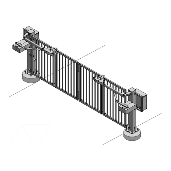
Page 147: Foldsmart Xt Drawings: Generic Site Layout And Options
FoldSmart XT Drawings: Generic Site Layout and Options... -
Page 159: Foldsmart
FOLDSMART 3 YEAR LIMITED PRODUCT WARRANTY For a period of 3 Years from date of delivery, Wallace Perimeter Security (“WPS”) warrants the product delivered to Buyer as follows: (1) the hardware shall be free from defects in material and workmanship and will conform to the applicable WPS specification and the terms of this proposal, and (2) the software and firmware will conform to the applicable WPS specifications and the terms of use. -
Page 161: Technical Specifications
However, an additional monitored sensor is required if there is a risk of entrapment in both directions of gate travel. Visit https://support.hysecurity.com/hc/en-us/ categories/360003177593-Safety for more information on UL 325 standards and gate safety. FoldSmart™ Installation and Maintenance Manual Revision 1 - MAY 2023... - Page 162 115 Lowson Crescent Winnipeg, Manitoba, Canada R3P 1A6 Phone: 866.300.1110 wallaceperimetersecurity.com...
Need help?
Do you have a question about the FOLDSMART and is the answer not in the manual?
Questions and answers