Table of Contents
Advertisement
Advertisement
Table of Contents

Related Manuals for Wallace Perimeter Security Kinetic 1


Summary of Contents for Wallace Perimeter Security Kinetic 1
-
Page 4: Table Of Contents
Contents Introducing Kinetic DC KINETIC COMPONENTS Intro ..............................INTELLIGENT FEATURES SMART DC CONTROLLER Intro ..................... ™ TECHNICAL SUPPORT Intro ..............................INSTALLER’S CHECK LIST Intro ..............................Chapter: Safety Requirements IMPORTANT SAFETY INSTRUCTIONS ..........................Safety Standards – Installer’s Responsibility ........................Safety Standards – Owner / User Responsibility ........................ - Page 5 Contents RUN MODE ........................................Understanding Gate Status Displays ............................Using Smart DC Controller Buttons in RUN Mode ......................Viewing Operator Status Displays ............................USER MENU ........................................Adjusting the Closer Timer ................................ Setting the Time & Date ................................Setting AC Power Loss Gate Function 3-10 ..........................
- Page 6 Contents Kinetic Schematics 6-24 ..................................GENERAL MAINTAINANCE 6-26 ..............................Smart Touch Analyze and Retrieve Tool 6-26 ..........................What You Need 6-26 ................................. Installing START Software 6-26 ............................ . Setting User Account Controls 6-27 ..........................Electrical Controls 6-27 ..................................Mechanical Maintenance 6-28 ...............................
- Page 7 Fax or Mail this completed form to: HySecurity, Inc Fax: 888-321-9946 6623 South 228 Street E-mail: info@hysecurity.com Kent,WA 98032 For technical support call: 866-300-1110 Wallace Perimeter Security does not share warranty registration information with parties unless the requested services, transactions, or legal requirements necessitate it.
-
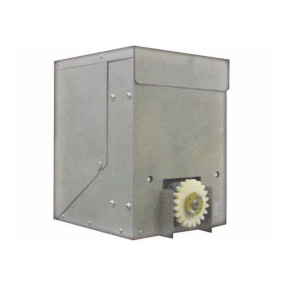
Page 8: Kinetic Components
Kinetic Components Kinetic Components Note: Refer to Parts & Limited Warranty for Kinetic parts list. Rev: A Intro-1... -
Page 9: Intelligent Features Smart Dc Controller ™
Introducing Kinetic DC Thank you for purchasing our premium Kinetic DC™ slide gate operator. At Wallace Perimeter Security, we pride ourselves on quality. Our new line electromechanical gate operators include a number of unparalleled user benefits: Robust - The components on the Smart DC Controller are protected by opto-isolators which shield them ™... -
Page 10: Technical Support
Technical Support For technical support, call your installer or authorized Wallace Perimeter Security distributor. Obtain the serial number of your operator before calling. Refer to Kinetic Components on the front page. For the name of a distributor near you, call Wallace Perimeter Security at 866-300-1110. -
Page 11: Installer's Check List
Installer’s Check List The following list provides a high level overview of the tasks involved in installing the Kinetic DC gate operator. Take a moment to review the list and check off the items as you complete the install. Make sure gate installation complies with ASTM F2200 Standard Specification for Automated Vehicular Gate Construction. -
Page 12: Important Safety Instructions
Kinetic gate operator. A qualified installer has one of the following: • A minimum of three years experience installing similar equipment. • Proof of attending a Wallace Perimeter Security Technical Training seminar within the past three years. • Significant manufacturer endorsements of technical aptitude in gate operator installation and operation. - Page 13 Important Safety Information Before attaching the operator to the gate, slide the gate in both directions. Make sure it is level and moves freely. A gate that slides easily reduces strain on operator components. Gravity should play no part in the opening or closing of the gate.
-
Page 14: Safety Standards – Owner / User Responsibility
Important Safety Information Safety Standards – Owner / User Responsibility • Automatic gates are for vehicular use only; provide and maintain walkways and signs to direct pedestrians to a separate walk-through entrance • An automatic gate can start at any time without warning; always keep people away from the gate area. •... -
Page 15: Hazardous Materials And Proper Disposal
To reduce the risk of injury to persons: • Observe the polarity between the batteries and charging circuit. • Never mix battery sizes, types, or brands. The charging circuit on Wallace Perimeter Security DC operators is designed for AGM-type batteries, not lead acid-type batteries. Wallace Perimeter Security strongly recommends that only sealed AGM style batteries be used. -
Page 16: Secondary Entrapment Protection Sensors
Secondary Entrapment Protection Sensors Secondary Entrapment Protection Sensors Kinetic is equipped with a primary, Type A, inherent entrapment sensor (IES). UL 325 Safety Standard compliance requires installation of secondary entrapment protection sensors, the number of which, depends on the entrapment hazards that exist at each particular installation. To comply with UL 325, the following external sensors may be used: •... - Page 17 Secondary Entrapment Protection Sensors Identifying Gate Operator Category & Usage Class The Kinetic operator, according to UL 325 Safety Standards, falls in the Slide Gate and Vertical Barrier Arm category for gate operators. Its usage class is determined by the area that the vehicular gate services. Four different vehicular usage classes are defined by UL 325: Class 1 Class I: Intended for use in a location of one to four single family dwellings or a...
-
Page 18: Choosing Secondary Entrapment Protection
UL 325 in Class IV applications, but it is not recommended by Wallace Perimeter Security because a buzzer warns, but cannot protect against possible entrapment. Wallace Perimeter Security highly recommends, even for Class IV use, that secondary entrapment protection (edge or photo-eye sensor) devices be installed to detect possible entrapment. -
Page 19: Emergency Stop Button
Secondary Entrapment Protection Sensors Emergency Stop Button An emergency stop button that is accessible from the outside of the operator is a requirement for compliance with UL 325 Safety Standards. The red emergency stop button is located inside a hole cutout on the Kinetic cover. -
Page 20: Safety Notices
Safety Notices Safety Notices The following four levels of safety notices are used where applicable within this manual; each notice contains information specific to the situation. Common Industrial Symbols The following international safety symbols may appear on the product or in its literature. The symbols are used to alert you to potential personal injury hazards. - Page 21 Common Industrial Symbols This page left intentionally blank S-10 Rev: A...
- Page 22 Installation Chapter 1 Kinetic DC 15W Kinetic DC 10FW Duty cycle: continuous Duty cycle: continuous Power: single phase, Switch selectable Power: single phase, Switch selectable 115 volts, 3 amps, 50/60 Hertz 115 volts, 3 amps, 50/60 Hertz 230 volts, 1.5 amps, 50/60 Hertz 230 volts, 1.5 amps, 50/60 Hertz Motor: ½...
-
Page 23: Installing The Kinetic Operator On Gate Post
Installing the Drive on Gate Post Installing the Kinetic Operator on Gate Posts RH & LH mounting options can be configured by the following steps: 1) Remove the 4 - 10x1.5 x 20mm button head screws on the side of the operator that will be mounted to the gate post. - Page 24 Installing the Drive on Gate Post Adjusting the Drive Height: 1) Raise the operator to the correct height so that it engages the toothrack in the gate beam. Clearance between the toothrack and spur gear should be .11” (2.7mm); an 11ga tie wire can be uses as a gauge to set the correct clearance.
- Page 25 Installing the Drive on Gate Post Installing the Toothrack: Hook toothracks together and slide them into rail throughout the entire length of gate. See Figure 1-7. Toothracks can be .80” (2cm) to 1.18” (3cm) shorter than gate length; it must not protrude past the end of the gate beam.
-
Page 26: Connecting The Battery And Turning Dc Power On
Installing the Drive on Gate Post Connecting the Battery and Turning DC Power ON: 1. Connect the red battery wire to its spade terminal. See Figure 1-10 2. Turn DC power ON. The USAGE CLASS appears when power is first supplied to the operator. -
Page 27: Programming The Initial Setup Menu
Installing the Drive on Gate Post Programming the Initial Setup Menu: Several sequential displays present information which must be configured before Kinetic operator will function. Once the configuration is complete, the information is retained even when a power loss occurs. Table 1-1. -
Page 28: Installing The Target Magnet
Installing the Drive on Gate Post Establishing the OPEN & CLOSE Limits The LEARN LIMITS display automatically appears after you set the gate weight. To set the open and close limits, take the following steps: 1. Hold the OPEN button until the gate slides to full open. Release the OPEN button. - Page 29 Installing the Drive on Gate Post Installing the Target Magnet Figure 1-13 1 . With the gate CLOSED, mark the gate beam directly across from target sensor that is closest to the trailing edge of the gate. See Figure 1-13. 2 .
- Page 30 Installing the Drive on Gate Post 8. To verify that the operator recognizes the target magnet, turn off both DC and AC power switches and watch the display go blank. Then, turn both switches on. The operator beeps indicating Limit Relearn Mode.
-
Page 31: Installing The Earth Ground
National Electric Code (NEC) requires a separate earth ground in addition to the required equipment ground. Wallace Perimeter Security recommends grounding the operator with a separate earth ground rod to shield the operator against electromagnetism and other electrical signals that may cause erratic operation with or damage to the Smart DC Controller. - Page 32 Installing the Earth Ground Installing the Earth Ground Take the following steps to comply with NEC and NFPA 780 standards: 1. Install a grounding rod per local building codes. See Figure 2-1. 2. Attach a large earth ground wire (6AWG) from the grounding rod to the lug nut on the base of the chassis.
- Page 33 Wiring AC Power Wiring AC Power Turn off AC power at the source (circuit breaker panel) before accessing the wires in the Kinetic junction box. Follow facility Lock Out/Tag Out procedures. Make sure both the DC and AC power switches, on the side of the Kinetic control box are in the off position.
-
Page 34: Wiring 115Vac Power
Wiring AC Power Wiring 115VAC Power For standard 115VAC power connection: • Verify AC power supply wires and low voltage (12V & 24V accessory power wires) run through two separate conduits. The higher voltage from the AC power supply may cause interference and anomalies in Kinetic operation if the high and low voltage wires are routed through the same conduit. -
Page 35: Wiring 230Vac Power
Wiring AC Power Wiring 230VAC Power All Kinetic operators are shipped from the factory as 115VAC units. When connecting to 230VAC power, the voltage selector switch on the AC power board must be moved to the 230V position or damage to the operator will occur and void the Limited Warranty. For 230VAC power connection: •... -
Page 36: Using A Solar Powered Operator
8. Place the 230V 1 label on the junction box cover, over the 115V 1 label. Using a Solar Powered Operator Wallace Perimeter Security offers a solar version of the Kinetic operator in 1ft/s or 2ft/s models. The solar models have different internal wiring and include software programmed for solar use. The Smart DC Controller has a built in charger which allows a 24V solar panel (or two 12V panels) a direct connection to the Kinetic operator with no additional electronic devices required. - Page 37 Using a Solar Powered Operator Figure 2-4 Solar Panels and Wiring Connections Green Black Figure 2-5 Kinetic DCS Control Box Control Box DC Battery & Motor Switch (OFF) Red Spade Connector DC Solar Panel Switch (OFF) Input & Ground Wires Rev: A...
- Page 38 Using a Solar Powered Operator Connecting Peripherals to a Solar Operators: The 24VAC power supply shown in Figure 2-6 is not to be used for peripheral connections because the 24VAC terminals are directly connected to the solar panel inputs. Any peripherals attached to the 24VAC terminals could be severely damaged due to varying voltage levels.
-
Page 39: Understanding Gate Activity Based On Solar Zones
Sites requiring more than 1,500 feet of gate travel per day or those sites located in less sunny climes, need larger capacity batteries. Wallace Perimeter Security offers a 50Ah battery option which provides six times the storage capacity of the standard 8Ah batteries. -
Page 40: Important Consideration For Dc Powered Operators
32 F (0 C) -22 F (-27 C) • Wallace Perimeter Security uses a permanently sealed AGM-type battery which last much longer than wet cell batteries and needs no maintenance over its life span. Batteries are protected from over discharge by a low voltage sensing circuit. -
Page 41: Installing The Extended Battery Backup Kit
Installing the Extended Battery Backup Kit Figure 2-8 Wallace Perimeter Security offers an extended DC power back up option with two 50Ah batteries. Contact Wallace Perimeter Security parts department to order extended battery backup kit with base extension. To install the extended battery backup kit: 1. - Page 42 Important Considerations for DC Powered Operators 7. Using the wires supplied in the 50Ah battery kit, attach the red wire to the red positive terminal on the 50Ah battery. Connect its opposite end to the red lead exiting the support bracket. 8.
- Page 43 Important Considerations for DC Powered Operators This page intentionally blank. 2-13 Rev: A...
-
Page 44: Initial Setup
Display and Menu Options Chapter 3 This section of the manual provides information about the display and menu options. It includes how to: 1. Turn both AC and DC power switches on. 2. Review how to use the Smart DC Controller Buttons in Menu Mode. 3. -
Page 45: Turning Both Power Switches On
Initial Setup Turning Both Power Switches ON AC and DC power switches are located on the outside edge of the control box. See Figure 3-1. After Programming the Initial Setup Menu, Establishing the OPEN & CLOSE Limits, Installing the Target Magnet, and connecting to main power (Power), take the following steps: 1. - Page 46 Initial Setup Using the Smart DC Controller Buttons in Menu Mode The buttons on the Smart DC Controller let you navigate, change, or clear the information in the display menus. Refer to Figure 3-3. The buttons with text above and below have two functions. Use these buttons to enter operating commands or navigate through the User and Installer Menus.
-
Page 47: Run Mode
Run Mode Run Mode Gate status displays appear when the operator is ready and waiting for a gate operation command. When the menu display is flashing “GATE OPENING” or “GATE CLOSING” a command has been received which starts the motor and drives the gate. The command may come from a variety of sources: a card reader, pushbutton remote, or recognition of a vehicle passing over a free exit loop detector. -
Page 48: Using Smart Dc Controller Buttons In Run Mode
Run Mode Using the Smart DC Controller Buttons in RUN Mode The Run Mode buttons are distinguished by the fact that their name appears above each button. The Controller buttons with text above and below function differently depending on the mode of the operator. Three different modes exist: •... -
Page 49: Viewing Operator Status Displays
Run Mode Viewing Operator Status Displays Press the MENU button once and the operator status displays appear in two second intervals. Pertinent information appears to provide a quick overview of the operator’s status or configurations. Refer to Figure 3-6. Rev: A... -
Page 50: User Menu
User Menu User Menu The User Menu consists of several items which can be modified using the Smart DC Controller buttons. Refer to Using the Smart DC Controller Buttons In Menu Mode. To access the User Menu, take the following steps: 1. - Page 51 User Menu Adjusting the Close Timer The close timer assigns how many seconds will pass before the operator initiates closure of a fully opened gate after all open commands and reversing sensor inputs have ceased. Every gate operator needs to have the close timer set to a specific number of seconds unless a hard-wired closing device is connected to the unit such as a push button station.
- Page 52 User Menu Setting the Time and Date A feature of the Smart DC Controller is its 24-hour, 365 day clock. Make sure it is set to the appropriate time zone. An accurate time and date allows the diagnostic log to date stamp operational data which indicates when Alerts, Faults and Errors occur.
-
Page 53: Setting Ac Power Loss Gate Function
User Menu Setting AC Power Loss Gate Function The setting in the AC LOSS display determines what action the operator performs during an AC power loss. The settings help reduce drain on the battery. You can choose between four settings depending on customer preferences. -
Page 54: Adjusting The Display Contrast
User Menu Adjusting the Display Contrast The display contrast can be adjusted from 1 to 9 to increase visibility and ease of use. It is set at the factory to level 5. The text becomes darker as you go up the scale. To adjust the contrast (1 to 9), take the following steps: 1. - Page 55 User Menu 3-12 Rev: A...
- Page 56 User Menu Rev: A 3-13...
- Page 57 User Menu 3-14 Rev: A...
-
Page 58: Installer Menu
Installer Menu Installer Menu The Installer Menu consists of several functions which can be modified using the Smart DC Controller buttons or configured through the use of a laptop computer and the START software available from the HySecurity website. The Installer Menu options provide more advanced configurations for the Kinetic operator. Access to the Installer Menu is through the User Menu. -
Page 59: Resetting The Open & Close Limits
Installer Menu Resetting the OPEN and CLOSE Limits On occasion, the open and close limits may need to be fine-tuned. Resetting the open and close limits is easily accomplished by accessing the Installer Menu. Examples where resetting the limits is necessary, include: •... -
Page 60: Adjusting Gate Speed
Installer Menu Installer Menu The Installer Menu consists of several functions which can be modified using the Smart DC Controller buttons or configured through the use of a laptop computer and the S.T.A.R.T. software available from the HySecurity website. The Installer Menu options provide more advanced configurations for the Kinetic operator. Access to the Installer Menu is through the User Menu. -
Page 61: Adjusting Ies Sensitivity
Installer Menu Adjusting the IES Sensitivity The Installer Menu consists of several functions which can be modified using the Smart DC Controller buttons or configured through the use of a laptop computer and the START software available from the Hysecurity website. The adaptive IES software monitors the average running motor current while the gate is in motion and reverses the gate when the current exceeds an automatically self-adapting... - Page 62 Installer Menu NOTE When changing the IES setting, consider the site design and vehicular gate traffic. It is recom- mended that you use the most sensitive setting while still allowing for reliable gate operation. Examples of conditions which affect IES sensitivity incl Gate design - For long and/or solid gates in windy environments, large variations in motor current may...
-
Page 63: Reinstating The Factory Defaults
Installer Menu Reinstating Factory Defaults Ten menu configurations are available in the User Menu. Several other items in the Installer Menu let you customize the operator depending on the number of attached accessories and your customer’s needs. Reinstating factory default clears ALL menu settings stored in the operator and returns them to factory defaults. -
Page 64: Enabling The Fire Department Override
Installer Menu Enabling the Fire Department Override Many counties and cities require a Fire Department override system for gate operators. The fire department’s alert system is a separate unit that must be connected to the Smart DC Controller. The FIRE DEPARTMENT OPEN option must be properly configured through the Installer Menu before the operator will recognize the alert system. - Page 65 Installer Menu 3-22 Rev: A...
- Page 66 Installer Menu Rev: A 3-23...
- Page 67 Installer Menu 3-24 Rev: A...
- Page 68 Installer Menu Rev: A 3-25...
- Page 69 Installer Menu 3-26 Rev: A...
- Page 70 Installer Menu Rev: A 3-27...
- Page 71 Installer Menu 3-28 Rev: A...
- Page 72 Installer Menu Rev: A 3-29...
- Page 73 Installer Menu 3-30 Rev: A...
- Page 74 Installer Menu This page intentionally blank. Rev: A 3-31...
-
Page 75: Chapter 4: Smart Dc Controller
Smart DC Controller Chapter 4 This section of the manual contains information about the Smart DC Controller board; its inputs for peripheral connections and its monitoring capabilities. This section explains how to: 1. Make connections on the Smart DC Controller. 2. -
Page 76: Overview Of The Smart Dc Controller
Overview of the Smart DC Controller Overview of the Smart DC Controller The Smart DC Controller uses LED’s to indicate active inputs when AC power is present. For operators that use only DC power, you can push a button to show the active inputs. This button is at the bottom left corner near the EMERG OPEN input. - Page 77 Overview of the Smart DC Controller All the control device inputs listed in Table 4-1 are shown as a single input. The second wire is connected to a Common Terminal Bus (1 - 8) on the Smart DC Controller board. The Fire Department Open input is an exception and requires a +24VDC input as well as activation through the Installer Menu.
-
Page 78: Vehicle Detector Installation Options
Overview of the Smart DC Controller Vehicle Detector Installation Options The Smart DC Controller provides a feature-rich interface to four different vehicle detector inputs. NOTE Standard box type 11 pin (24 Volt DC or 24 Volt AC) vehicle detectors may be connected in the traditional manner as described in Installing Standard 11-Pin Box Type Vehicle Detectors. - Page 79 Overview of the Smart DC Controller There are four vehicle detector inputs available on the Smart DC Controller: • Free Exit Loop Detector - This opens a fully closed gate or reopens a closing gate. • Outside Obstruction Loop Detector (Out Obs Loop) - Reversing loop on public side. •...
- Page 80 Overview of the Smart DC Controller 9. Sensitivity is the only adjustment available on the detector itself. Generally, sensitivity does not need to be increased unless the loop is large or there are multiple loops connected to one detector. NOTE A boost feature is applied for settings 0 through 3.
- Page 81 Overview of the Smart DC Controller Connecting Standard 11-Pin Box Type Vehicle Detectors NOTE If photo eyes are used to monitor vehicle traffic instead of loop detectors, connect the photo eyes using the same steps. See Installing Photoelectric Sensors For Secondary Entrapment Protection only.
-
Page 82: Vehicle Detectors Configuration And Quick Close Mode Selection
Overview of the Smart DC Controller Figure 4-4 – Standard 11 Pin Box Type Vehicle Detector Vehicle Detector Configuration and Quick Close Mode Selection The Standard Quick Close modes are selectable in the Installer Menu. Refer to Table 3-2 on page 3-21. The four selectable modes are described as follows: Mode 1: (Default) An input from either the Free Exit, Outside Obstruction Loop, Inside Obstruction Loop or the... -
Page 83: Connecting Accessory Devices
Connecting Accessory Devices Entrapment Sensor Connections Devices, such as gate edge sensors and photoelectric beams, must be installed to protect against entrapment. These secondary entrapment protection devices are required so the gate installation is in compliance with UL 325 Safety Standards. Figure 4-5 illustrates how to connect different sensors to the Smart DC Controller: Figure 4-5 Entrapment Sensor Connections Rev: A... -
Page 84: Manual Push Button Station
Connecting Accessory Devices Manual Push Button Stations A manual push button station controls the gate operator and opens, stops, and closes the gate. It is most often used by a guard in a 24-hour guard station. An example of the push button station connections on the Kinetic DC operator is shown in Figure 4-6. -
Page 85: User Relays - Programming Procedure
Connecting Accessory Devices User Relays – Programming Procedure The Smart DC Controller is able to interface with many types of external devices through the use of two user programmable output relays. All of the user relay functions identified and described in Table 4-3 are accessible in the Installer Menu.: NOTE The User Relays will operate normally to less than 18VDC. - Page 86 Connecting Accessory Devices Rev: A 4-12...
- Page 87 Connecting Accessory Devices This page intentionally blank. 4-13 Rev: A...
-
Page 88: Chapter 5: Bi-Parting Gate Systems
Bi-parting Gate Systems Chapter 5 Configuring two operators to be a Master and Slave pair is easy with the Smart Touch DC Controller. There is no need to order a special model or any adapters. The area of the board marked Dual Gate employs a 3wire RS485 serial port for communication between master and slave operators. - Page 89 Master/Slave Configuration Master and Slave Wiring Connections Figure 5-2 1. As shown in Figure 5-2, connect a shielded communications cable to the DUAL GATE inputs in each unit. The inputs are located near the base of the Smart DC Controller. Be sure to connect the wires in pairs to the same terminal ports (A-A, B-B, and COM to COM) on both units.
-
Page 90: Master & Slave Menu Setup
Master/Slave Configuration Master / Slave Menu Setup Determine which unit will be set up as the Master. The other unit will be set up as the Slave. It doesn’t matter which unit is which, but you must identify the Master and Slave operators by taking the following steps: Start by configuring the MASTER unit. - Page 91 Master/Slave Configuration This page intentionally blank. Rev: A...
-
Page 92: Chapter 6: Reference
Reference Chapter 6 This section of the manual provides information which may be useful when installing Kinetic operators. It includes how to: • Connect a Radio Receiver for Remote Open • Install a Gate Locking Mechanism • Install Vehicle Detectors and Loops •... -
Page 93: Installing A Maglock Or Solenoid Lock
Installing a MagLock or Solenoid Lock 8. Set the “DIP” switches in the receiver to match the same code used in the transmitter. NOTE If an edge sensor transmitter is also used to reverse the gate, be certain to use a two channel commercial receiver. -
Page 94: Installing A Lock For 12Vdc Or 24Vdc Systems
Installing a MagLock or Solenoid Lock Installing a lock for 12VDC or 24VDC Systems To install a lock for 12VDC or 24VDC systems, take the following steps: 1. Connect a wire between COM on USER 1 RELAY and a COM terminal on the Smart DC Controller board. -
Page 95: Installing A Lock For 12Vac Systems
Installing a MagLock or Solenoid Lock Installing a lock for 12VAC To install a lock for 12VAC system, take the following steps: 1. Connect a wire from COM on USER 1 RELAY and one 24VAC power spade. See Figure 6-3. 2. -
Page 96: Setting The User Relay Function In The Installer Menu
Installing a MagLock or Solenoid Lock Setting the User Relay Function in the Installer Menu 5. Enter the Installer Menu and set the User 1 Relay to Function 6 - GATE LOCK OUTPUT. Rev: A... -
Page 97: Installing Vehicle Detectors And Loops
Installing Vehicle Detectors and Loops Setting the User Relay Function in the Installer Menu A vehicle detector passes a small current flow through the “loop” which then becomes an inductive coil. When a vehicle passes over the loop, the detector senses the resultant drop in the inductance and actuates the detector output. - Page 98 Installing Vehicle Detectors and Loops 9. This guide is written from a design perspective, but installation workmanship practices are equally important to insure proper operation and long loop life. The best way to insure a quality installation is to employ a professional installer experienced with detector loops. A few important practices are: •...
- Page 99 Installing Vehicle Detectors and Loops Rev: A...
-
Page 100: Operation Notes
Installing Photoelectric Sensors for Secondary Entrapment Protection Only Refer to Figure 6-8 to help plan the most appropriate placement for the photo eyes being installed as secondary entrapment protection devices. If no other secondary external entrapment protection devices (like edge sensors) are installed, then at least two photoelectric sensors are required to guard the gate in each direction of travel. - Page 101 Installing Photoelectric Sensors for Secondary Entrapment Protection Only There are two common types of photoelectric sensors, thru-beam and retro-reflective, and each has its advantages. • A thru-beam sensor is generally more powerful and able to function reliably with dirty optics and in port weather.
-
Page 102: Supervised Connection
Installing Photoelectric Sensors for Secondary Entrapment Protection Only • The photo eye NO or NC output wires connect to the Smart DC Controller at the EYE CLOSE terminal if the photo eye spans the road, or at the EYE OPEN terminal if the photo eye spans the area between an open gate and a wall or other structure. - Page 103 Installing Photoelectric Sensors for Secondary Entrapment Protection Only Taking steps to protect the photo eye and the reflector from being exposed to fog and being absolutely certain the photo eye is perfectly aligned will greatly reduce any false triggering of the system. The ideal mounting of a retro-reflective photo eye is inside an enclosure.
- Page 104 Installing Gate Edge Sensors Installing Gate Edge Sensors Refer to Figure 6-11 to help plan the most appropriate placement of the edge sensors being installed. For sliding gates, one or more contact sensors (edge sensors) must be located at the leading edge, trailing edge and post-mounted both inside and outside of the sliding gate.
-
Page 105: Installing Gate Edge Sensors
Installing Gate Edge Sensors Edge sensors that are not attached to the moving gate, such as post mounted sensors, must be wired in parallel and directly connected to the gate operator: • If the gate is sliding open to a wall with less than 16"... -
Page 106: Smart Dc Controller Troubleshooting
For diagnostic purposes these messages can be retrieved with optional START software available from Wallace Perimeter Security. Refer to Smart Touch Analyze and Retrieve Tool. The following Table 6-1 provides solutions to the error codes, faults, and alerts that may appear on the Smart DC Controller display. - Page 107 Smart DC Controller Troubleshooting 6-16 Rev: A...
- Page 108 Smart DC Controller Troubleshooting Rev: A 6-17...
- Page 109 Smart DC Controller Troubleshooting 6-18 Rev: A...
- Page 110 Smart DC Controller Troubleshooting Rev: A 6-19...
- Page 111 Smart DC Controller Troubleshooting 6-20 Rev: A...
- Page 112 Smart DC Controller Troubleshooting Rev: A 6-21...
- Page 113 Smart DC Controller Troubleshooting Vehicle Detector Loop Fault Diagnostics If Wallace Perimeter Security HY-5A vehicle detector modules are used, the Smart DC Controller has the ability to store and report detector and loop fault information for performance diagnostics. If the Smart DC Controller senses a loop or detector problem: •...
- Page 114 Faults and Errors can be retrieved from the Smart DC Controller by downloading from the RS232 communications port or the USB port. Wallace Perimeter Security’s free START software, a laptop computer, and a special download cable or USB cable are required to retrieve and read this data.
-
Page 115: Kinetic Schematics
Smart DC Controller Troubleshooting Kinetic Schematics Figure 6-14 - illustrate the schematics for the Kinetic DC 15W and Kinetic DC 10FW. Figure 6-15 shows the solar version. 6-24 Rev: A... - Page 116 Smart DC Controller Troubleshooting Figure 6-15 Rev: A 6-25...
-
Page 117: Smart Touch Analyze And Retrieve Tool
What You Need Figure 6-16 • Standard USB 2.0 A-B communications cable. If you are using the Wallace Perimeter Security RS-232 to USB adapter, be sure to install the USB driver in your laptop. • Laptop computer with Windows PC operating system (XP, Vista, or Windows 7) •... -
Page 118: Setting User Account Controls
9. 7. Follow the step-by-step instructions to complete the installation. 8. When the download is complete, log out of the Wallace Perimeter Security website. Shortcuts for the START and Smart DC Controller History Logs appear on your laptop’s desktop. -
Page 119: Mechanical Maintenance
General Maintenance Mechanical Maintenance Before checking the internal mechanisms of the operator, turn off all power switches. The Kinetic mechanical maintenance is not in depth or difficult, but should be performed on a routine basis. The operator chassis is zinc plated, but some environments may speed corrosion of this plating. Schedule regular maintenance and look for the following: •... -
Page 120: Drive Belt Tension And Alignment
General Maintenance Drive Belt Tension and Alignment Figure 6-17 Proper drive belt tension is important for prolonging the life of the drive belt and maintaining the superior performance of the operator. To check the drive belt tension, take the following steps: 1. -
Page 121: Dc Battery Replacement
General Maintenance DC Battery Replacement Wallace Perimeter Security provides a one-year warranty from the date of shipment for all batteries supplied with the Kinetic operator. Indicators of a low battery include: • LOW BATTERY or DEAD BATTERY appears on the Smart DC Controller display which may or may not be indicative of normal discharge. - Page 122 General Maintenance To install the two new batteries, reverse the removal procedure. 1. Connect the red wire to red terminal on the left battery and slide the battery onto the tray. 2. Attach the blue wire to the black terminal. 3.
-
Page 123: Clock Battery Replacement
General Maintenance Clock Battery Replacement A lithium coin battery supports the clock so the date and time is retained even when the main power is turned off. See Figure 6- 21. Replace the battery about every five years (or as needed) with a DL 2025, DL 2032, or CR 2025, or CR 2032 battery. - Page 124 General Maintenance This page intentionally blank. Rev: A 6-33...
- Page 125 6623 South 228 Kent,WA 98032-1872 www.hysecurity.com 1-800-321-9947 LIMITED WARRANTY...
- Page 126 5 years commercial use (7 years for single-family residence) for single-family residence) Copyright 2011 all rights reserved. No part of this manual may be reproduced by any means (photocopier, electronic, or mechanical), without the express written permission of Wallace Perimeter Security and HySecurity Gate Inc..
- Page 127 The optimum gap is 2.7mm – roughly the diameter of an 11 gauge tie wire. 1.6 Wallace Perimeter Security Logo ________ Installation Checklist & Sign Off Page 1 2012.01.06...
- Page 128 A: 90 Lowson Crescent, Winnipeg, MB, Canada, R3P 2H8 The Wallace Perimeter Security logo should be placed starting/ending (depending on the direction of the gate) at the third picket from the front of the beam, facing the public side of the property.
- Page 129 2.12 Smart DC Controller Software Version ________ Check the software version on the Smart DC board. If not the latest version, contact the Wallace Perimeter Security service team to download new version, update and record new version number: __________ 2.13 Kinetic Serial Number...
Need help?
Do you have a question about the Kinetic 1 and is the answer not in the manual?
Questions and answers