Table of Contents
Advertisement
Quick Links
F4
F4 (AS06320)
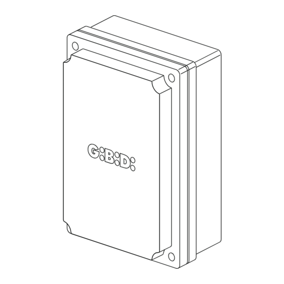
Apparecchiatura elettronica
ISTRUZIONI PER L'INSTALLAZIONE
Electronic control unit
INSTRUCTIONS FOR INSTALLATION
Appareillage électronique
INSTRUCTIONS POUR L'INSTALLATION
Equipo electrónico
INSTRUCCIONES PARA LA INSTALACIÓN
Elektronische besturing
INSTRUCTIES VOOR DE INSTALLATIE
IT
UK
FR
ES
NL
Advertisement
Table of Contents

Summary of Contents for GBD F4
- Page 1 F4 (AS06320) Apparecchiatura elettronica ISTRUZIONI PER L’INSTALLAZIONE Electronic control unit INSTRUCTIONS FOR INSTALLATION Appareillage électronique INSTRUCTIONS POUR L’INSTALLATION Equipo electrónico INSTRUCCIONES PARA LA INSTALACIÓN Elektronische besturing INSTRUCTIES VOOR DE INSTALLATIE...
-
Page 2: Technical Specifications
Thank you for choosing GIBIDI. CAREFULLY READ THESE INSTRUCTIONS BEFORE PROCEEDING WITH INSTALLATION. WARNINGS: This product has been tested by GI.BI.DI. for full compliance with the requirements of the directives in force. GI.BI.DI. S.r.l. reserves the right to change the technical data without prior notice in relation to product development. DISPOSAL: GI.BI.DI. -
Page 3: Installation Warnings
3 - INSTALLATION WARNINGS • Before proceeding with installation, fit a differential magnetothermal switch with a maximum capacity of 10A upstream of the system. The switch must guarantee omnipolar separation of the contacts with an opening distance of at least 3mm. •... - Page 4 5 - ELECTRICAL CONNECTIONS: TERMINAL BOARDS Terminal Position Signal Description Motor 1 connection (opening) Motor 1 connection (common) Motor 1 connection (closing) Motor 2 connection (opening) Motor 2 connection (common) Motor 2 connection (closing) COURTESY LIGHT output (LIVE) if DIP1_9 = OFF Fixed output for FLASHING LIGHT if DIP1_9 = ON COURTESY LIGHT output (NEUTRAL) if DIP1_9 = OFF Fixed output for FLASHING LIGHT if DIP1_9 = ON...
-
Page 5: Protection Fuses
6 - PROTECTION FUSES Position Value Type Description Protects the circuit board and the motors. 6.3A 160mA Protects the circuit board and the accessories. 7 - WARNING LEDs Colour Signal Description Always on. Turns off when the CLOSING LIMIT SWITCH of motor 2 is reached. FCCM2 Always on. - Page 6 8 - DIP SWITCH DIP1 The settings are stored during the rest phase (gate closed The default settings are highlighted in the boxes with grey background . Function Status Description When the photocell is broken/interrupted during both opening and closing, the gate motion is ceased until the photocell is re-made.
- Page 7 Disables the limit switch input MOTOR 1 OPENING DIP1_4 LIMIT SWITCH Enables the limit switch input Disables the limit switch input MOTOR 1 CLOSING DIP1_5 In the case of a system with only one LIMIT SWITCH Enables the limit switch input motor and using the limit switches, the DIP switches 4, 5, 6 and 7 are Disables the limit switch input...
-
Page 8: Trimmer Adjustment
10 - JUMPER SW15 The settings are stored during the rest phase (gate closed). The default settings are highlighted in the boxes with grey background. JUMPER Function Status Description N.C. devices are connected to STOP/EDGE input (23) TERMINAL 23 SW15 FUNCTIONING Resistive 8,2KOhm devices are connected to STOP/EDGE input (23) 11 - TRIMMER ADJUSTMENT... - Page 9 • Power the device. • Check that the red LEDs of the N.C. contacts are on and the green LEDs of the N.O. contacts are off. • Check by tripping the limit switches (if used and enabled with the appropriate DIP switches) that the corresponding LEDs go off.
- Page 10 Movements made during the learning with 2 motors: Ÿ Motor 2 closes until running into the limit switch or until receiving a START impulse. Ÿ Motor 1 closes until running into the limit switch or until receiving a START impulse. Ÿ...
-
Page 11: Soft Start
14 - SOFT START This function adds 1s at reduced speed at the beginning of each movement. It is particularly recommended for the electromechanical operators. Write down DIP1_1 position. Ÿ Cut power to the control unit. Ÿ Press and hold MEMO button. Ÿ... - Page 12 Michele Prandi CE Declaration of conformity The manufactuerer: GI.BI.DI. S.r.l. Via Abetone Brennero, 177/B, 46025 Poggio Rusco (MN) ITALY Declares that the product: ELECTRONIC CONTROL UNIT F4 are in conformity with the following directives: 2014/35/UE 2014/53/UE Ÿ Ÿ 2014/30/UE 2011/65/UE Ÿ...
- Page 13 IT-UK NOTE / NOTES...
- Page 14 NOTE / NOTES...
- Page 15 GI.BI.DI. S.r.l. Via Abetone Brennero, 177/B 46025 Poggio Rusco (MN) - ITALY Tel. +39.0386.52.20.11 Fax +39.0386.52.20.31 E-mail: info@gibidi.com Numero Verde: 800.290156 w w w . g i b i d i . c o m...


Need help?
Do you have a question about the F4 and is the answer not in the manual?
Questions and answers