Advertisement
Available languages
Available languages
Quick Links
IB51402521
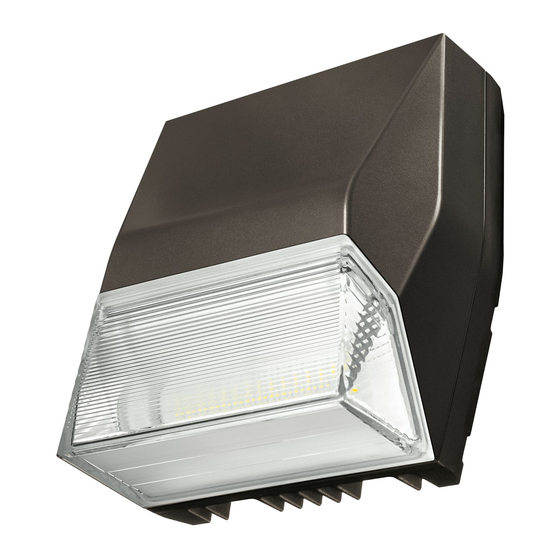
Installation Instructions – Axcent (Small & Large)
Instructions d'installation – Axcent (petit et grand)
Instrucciones de instalación – Axcent (pequeño y grande)
Risk of Fire, Electrical Shock, Cuts or other Casualty Hazards- Installation and maintenance of this
product must be performed by a qualified electrician. This product must be installed in accordance
with the applicable installation code by a person familiar with the construction and operation of the
product and hazards involved.
Risk of Fire and Electric Shock- Make certain power is OFF before starting installation or attempting
any maintenance. Disconnect power at fuse or circuit breaker.
Risk of Fire- Refer to product label for specific minimum supply conductor requirements.
Risk of Burn- Disconnect power and allow fixture to cool before handling or servicing.
Risk of Personal Injury- Fixture may become damaged and/or unstable if not installed properly.
Failure to comply with these instructions may result in death, serious bodily injury and property damage.
N
ote:
These instructions do not claim to cover all details or variations in the equipment, procedure, or process
described, nor to provide directions for meeting every possible contingency during installation, operation
or maintenance. When additional information is desired to satisfy a problem not covered sufficiently for
user's purpose, please contact your nearest representative.
N
ote:
Care must be taken not to set lighting fixture down on optical lenses or lift the fixture in the lens area.
N
ote:
Specifications and dimensions subject to change without notice.
N
ote:
If the light fixture is ordered with the CBP (Cold Weather Battery Pack) option, then "this luminaire is
provided with a factory installed emergency lighting pack and must be serviced by a person familiar with
the construction and operation of product and hazards involved" .
DISCLAIMER OF LIABILITY: Cooper Lighting Solutions assumes no liability for damages or losses of any kind
that may arise from the improper, careless, or negligent installation, handling or use of this product.
NOTICE: Green ground wire provided in proper location. Do not relocate.
ATTENTION Receiving Department: Note actual fixture description of any shortage or noticeable damage on
delivery receipt. File claim for common carrier (LTL) directly with carrier. Claims for concealed damage must be
filed within 15 days of delivery. All damaged material, complete with original packing must be retained.
Safety: This fixture must be wired in accordance with the National Electrical Code and applicable local codes and
ordinances. Proper grounding is required to insure personal safety. Carefully observe grounding procedure under
installation section.
APPLICATIONS: This lighting fixture is designed for outdoor lighting use, and should not be used in area of
limited ventilation or inside high ambient temperature enclosures. Not suitable for indoor use when installed in
inverted/uplight orientation.
NOTE: When the fixture is facing upward where debris may accumulate, add a wire guard or vandal shield as
needed to prevent debris from overheating the lens and/or the fixture.
NOTE: Fixture must be stored in a dry location before installation. Do not expose lighting fixture to rain, dust or
other environmental conditions before installation and insertion of photocontrol or shorting cap (if so equipped).
Best results will be obtained if installed and maintained according to the following recommendations.
WARNING
Brand Logo
reversed out of
black
Lumark
INS #
INS #
Advertisement

Related Manuals for Cooper Lighting Solutions Lumark Axcent Small


Summary of Contents for Cooper Lighting Solutions Lumark Axcent Small
- Page 1 . DISCLAIMER OF LIABILITY: Cooper Lighting Solutions assumes no liability for damages or losses of any kind that may arise from the improper, careless, or negligent installation, handling or use of this product.
-
Page 2: Installation
20 in-lbs. (Figure 5.) cases, the installer will label the gray building wire as a 0-10 dimming wire and connect to our product’s pink 0-10V dimming control wire. Reference NFPA70 (2020 NEC), section 410.69. Cooper Lighting Solutions IB51402521 Installation instructions... - Page 3 Tighten the two (Figure 6-7 .) ¼-20 screws on the fixture to 20 in-lbs. (Figure 6.) Install cover plate, tightening the (2) cover plate screws. (Figure 6-7 .) Cooper Lighting Solutions IB51402521 Installation instructions...
- Page 4 Figure 8. Axcent (Small & Large) causing connections to break and creating a shock hazard when power is turned on. Use wire nuts or other approved connectors to wire fixture per wiring diagram. (Figure 3.) Cooper Lighting Solutions IB51402521 Installation instructions...
- Page 5 Attach the quick-connect adapter to the fixture, pulling the luminaire supply leads through the wedge plate center hole. Tighten the (2) ¼-20 lock screws on the Figure 12. fixture to 20 in-lbs. (Figure 12.) Cooper Lighting Solutions IB51402521 Installation instructions...
- Page 6 Should be flush Screws and Tighten To 20In-Lbs. (2.3N-M) within 1/16” . Align Cover Tabs Cover Plate Screws. With Arm Slots Tighten To 20 In-Lbs (2.3N-M) Figure 13. Cooper Lighting Solutions IB51402521 Installation instructions...
- Page 7 être mis en service par une personne familière avec la construction, le fonctionnement du produit et les risques inhérents. EXONÉRATION DE RESPONSABILITÉ : Cooper Lighting Solutions n’assume aucune responsabilité pour les dommages ou pertes de quelque nature que ce soit pouvant découler d’une installation, d’une manipulation ou d’une utilisation inappropriée, imprudente ou négligente de ce produit.
- Page 8 0-10 V pincés entre la plaque de montage et le boitier. rose de notre produit. Référence : disposition 410.69 de la NFPA 70 (NEC de 2020). Cooper Lighting Solutions IB51402521 Instructions d’installation...
- Page 9 (Figure 1.) Effectuez les raccords électriques entre le luminaire et la fourche à emboîtement en utilisant les capuchons de connexion pour extérieur. Consultez le schéma de câblage pour effectuer les raccords d’alimentation électrique. (Figure 3.) Cooper Lighting Solutions IB51402521 Instructions d’installation...
- Page 10 (2) vis cruciformes de 1/4-20 à un couple de 20 lb/ 127 mm po (figure 9). Assurez-vous que les fils d’alimentation [5 po] électrique du luminaire ne sont pas coincés entre la plaque de calage et le boîtier. Figure 8. Axcent (petit et grand) Cooper Lighting Solutions IB51402521 Instructions d’installation...
- Page 11 Le bras de montage sur est conçu pour un poteau carré ou rond. L ’installation de poteau rond exigera que les languettes de rupture soient retirées. Utilisez des pinces pour retirer les languettes. (Figure 10.) Figure 12. Cooper Lighting Solutions IB51402521 Instructions d’installation...
- Page 12 Doit être encastré à au moins 1,6 mm (1/16 po). Alignez les languettes du Vis du couvre-joint. couvercle avec Serrez à un couple les fentes du de 2,3 Nm (20 po-lb) bras Figure 13. Cooper Lighting Solutions IB51402521 Instructions d’installation...
- Page 13 . RENUNCIA DE RESPONSABILIDAD: Cooper Lighting Solutions no asume ninguna responsabilidad por daños o pérdidas de ningún tipo que puedan derivarse de la instalación, manipulación o uso incorrecto, descuidado o negligente de este producto.
-
Page 14: Instalación
0-10 V y lo conectará al cable de control de regulación de 0-10 V rosa de nuestro producto. Consulte el código NFPA70 (2020 NEC), sección 410.69. Cooper Lighting Solutions IB51402521 Instrucciones de instalación... - Page 15 3/4 “ (sólo Axcent grande), conductor de tuerca cuadrada de 3/8” , llave dinamométrica. La luminaria viene con una placa de cuña preinstalada de montaje en la pared. Retire la placa de cuña de montaje en la pared y deséchela. (Figura 1.) Cooper Lighting Solutions IB51402521 Instrucciones de instalación...
- Page 16 NPS de 1/2” en la placa de cubierta (suministrado por otros). Asegure la placa de cubierta al nudillo con la tuerca de fijación y apriétela con un torque de 65 in-lbs. Nota: Asegúrese de que los cables no se pellizquen. Cooper Lighting Solutions IB51402521 Instrucciones de instalación...
- Page 17 El brazo de montaje en poste está diseñado para un poste cuadrado o redondo. La instalación en poste redondo requerirá la remoción de las lengüetas desprendibles del brazo de montaje. Use alicates para quitar las pestañas. (Figura 10.) Figura 12. Cooper Lighting Solutions IB51402521 Instrucciones de instalación...
- Page 18 Debe estar al ras dentro de 1/16” . Tornillos de la placa Alinee las pestañas de de cubierta. Apriete la tapa con las ranuras a 20 in-Lbs (2.3N-M) para los brazos Figura 13. Cooper Lighting Solutions IB51402521 Instrucciones de instalación...
- Page 19 Garantías y Limitación de Responsabilidad Visite www.cooperlighting.com/LightingWarrantyTerms para conocer nuestros términos y condiciones. Cooper Lighting Solutions 1121 Highway 74 South Peachtree City, GA 30269 P: 770-486-4800 Cooper Lighting Solutions is a www.cooperlighting.com registered trademark. All trademarks are property Canada Sales of their respective owners.
Need help?
Do you have a question about the Lumark Axcent Small and is the answer not in the manual?
Questions and answers