Table of Contents
Advertisement
Quick Links
Advertisement
Table of Contents

Related Manuals for Baker Hughes Panametrics oxy.IQ


Summary of Contents for Baker Hughes Panametrics oxy.IQ
- Page 1 oxy.IQ Panametrics Oxygen Transmitter User’s Manual BH024C11 EN G panametrics.com...
- Page 3 April 2023 panametrics.com Copyright 2023 Baker Hughes company. This material contains one or more registered trademarks of Baker Hughes Company and its subsidiaries in one or more countries. All third-party product and company names are trademarks of their respective holders.
- Page 4 [no content intended for this page]...
- Page 5 Preface Services Panametrics provides customers with an experienced staff of customer support personnel ready to respond to technical inquiries, as well as other remote and on-site support needs. To complement our broad portfolio of industry- leading solutions, we offer several types of flexible and scalable support services including: training, product repairs, extended warranties, service agreements and more.
- Page 6 Preface Working Area WARNING! Auxiliary equipment may have both manual and automatic modes of operation. As equipment can move suddenly and without warning, do not enter the work cell of this equipment during automatic operation, and do not enter the work envelope of this equipment during manual operation.
-
Page 7: Table Of Contents
Contents Chapter 1. Features and Capabilities ..........................1 Introduction ..................... . 1 Hazardous Location Certifications . - Page 8 Contents All Installations....................19 6.3.1 Process Wetted Materials .
-
Page 9: Chapter 1. Features And Capabilities
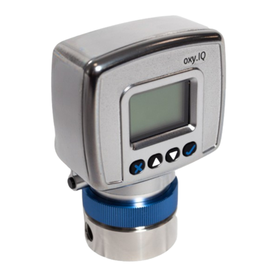
Chapter 1. Features and Capabilities Chapter 1. Features and Capabilities Introduction The oxy.IQ Panametrics Oxygen Transmitter (see Figure 1 below) is a highly reliable and cost-effective two-wire, loop-powered transmitter with a linearized 4 to 20 mA output. It measures oxygen content in ten ppm ranges (10, 20, 50, 100, 200, 500, 1000, 2000, 5000 and 10000 ppm) and eight percentage ranges (1, 2, 5, 10, 21, 25, 50 and 100%). -
Page 10: Features
Chapter 1. Features and Capabilities Features The oxy.IQ oxygen sensor is an advanced galvanic fuel cell that provides superior performance, accuracy, stability and long life. The cell’s innovative design eliminates the potential for negative signal output and reduces sources of contamination. -
Page 11: Sample Systems
Chapter 1. Features and Capabilities Sample Systems In addition to the standard features and options, Panametrics offers a full line of sample handling systems for a variety of applications. If needed, Panametrics can design and build a sample conditioning system to meet unique application requirements. - Page 12 Chapter 1. Features and Capabilities [no content intended for this page] oxy.IQ User’s Manual...
-
Page 13: Chapter 2. Installation
Chapter 2. Installation Chapter 2. Installation Mounting the oxy.IQ To install the oxy.IQ into the process or sample system, refer to Figure 9 on page 24 or Figure 2 below and proceed to the next page. Connector 2.05 1.58 Note: All dimensions are inches [mm]. [52.1] [40.3] 2.75... - Page 14 Chapter 2. Installation Figure 3: Packaged Oxygen Sensor Remove the sensor manifold by unscrewing it from the blue knurled nut on the sensor base at the bottom of the electronics module. IMPORTANT: The maximum operating sample pressure for the oxy.IQ is 10 psig except when the ambient air adapter is used for the sample manifold.
-
Page 15: Wiring The Oxy.iq
Chapter 2. Installation Wiring the oxy.IQ To wire the oxy.IQ, refer to Figure 14 on page 28, then proceed as follows: WARNING! For IS (Intrinsically Safe) applications, the oxy.IQ must be installed with a zener barrier (see the top of Figure 14 on page 28). Also, for installations in a hazardous location, the blue IS cable (p/n 704-1318-02, 10) must be used. -
Page 16: Installing An Oxygen Sensor
Chapter 2. Installation Installing an Oxygen Sensor To install a new or replacement oxygen sensor in the oxy.IQ, refer to figure 6 below and complete the following steps: Sensor Base Knurled Nut Oxygen Sensor Ring Sensor Manifold Figure 6: Oxygen Sensor Installation Disconnect the power from the oxy.IQ. -
Page 17: Chapter 3. Initial Setup And Operation
Chapter 3. Initial Setup and Operation Chapter 3. Initial Setup and Operation The oxy.IQ Display and Keypad All programming of the oxy.IQ is done via the front panel keypad and display, as illustrated below. Display Down Arrow Up Arrow Cancel Enter Figure 7: oxy.IQ Display and Keypad The front panel components perform the following functions:... -
Page 18: Adjusting And Calibrating The Oxy.iq
Chapter 3. Initial Setup and Operation Adjusting and Calibrating the oxy.IQ Upon startup, the following five-step adjustment and calibration procedure must be performed on the oxy.IQ: Select the desired output range. Trim the low (4 mA) and high (20 mA) analog outputs. Upon installation of a new oxygen sensor, calibrate the unit with air for either a ppm or % sensor. -
Page 19: Trimming The Analog Output High (20 Ma) End
Chapter 3. Initial Setup and Operation 3.3.2.3 Trimming the Analog Output High (20 mA) End Press the key and then press the Enter key to enter the 20 mA Trim menu, and the analog output is driven to about 20 mA. Use the keys to adjust the analog output up or down, until it equals 20.00 ±... -
Page 20: Recalibrating An Existing Sensor
Chapter 3. Initial Setup and Operation 3.3.3.2 Recalibrating an Existing Sensor For an existing sensor, continue the air calibration procedure as follows: Press the Enter key to select the NO menu option. As instructed, remove the sensor manifold to expose the oxygen sensor to ambient air for about two minutes. Then, press the Enter key to continue. -
Page 21: Chapter 4. User Programming
Chapter 4. User Programming Chapter 4. User Programming Introduction IMPORTANT: The oxy.IQ service menu is for use by qualified service personnel only and requires a special passcode for access. That menu is not discussed in this chapter. This chapter provides instructions for programming all of the oxy.IQ menu options available to the user, which can be accessed without the use of a passcode. -
Page 22: The Display Menu
Chapter 4. User Programming The Display Menu Proceed to the appropriate section to program the desired menu option. 4.3.1 Select the O Parameter To select the O parameter for display, complete the following steps: Press the Enter key to enter the Main Menu. Press the key once and then press the Enter key to enter the Display menu. -
Page 23: The Output Menu
Chapter 4. User Programming The Output Menu Proceed to the appropriate section to program the desired menu option. 4.4.1 Range See “Selecting the Output Range” on page 10. 4.4.2 Trim See “Trimming the Analog Output” on page 10. 4.4.3 Error Type To select the process conditions that will activate an on-screen warning and send an alarm to the analog output device, complete the following steps: Press the... -
Page 24: Error Output
Chapter 4. User Programming 4.4.4 Error Output To select the desired output value that will be sent to the analog output device upon an error, complete the following steps: Press the Enter key to enter the Main Menu. Press the key twice and then press the Enter key to enter the Output menu. -
Page 25: Chapter 5. The Service Menu
Chapter 5. The Service Menu Chapter 5. The Service Menu CAUTION! The Service Menu is intended for use by qualified service personnel only, and access to this menu requires entry of the service passcode. Misuse of the information in this menu may significantly impair the accuracy and performance of your oxy.IQ and may cause it to fail to meet its published specifications. - Page 26 Chapter 5. The Service Menu [no content intended for this page] oxy.IQ User’s Manual...
-
Page 27: Chapter 6. Specifications
Chapter 6. Specifications Chapter 6. Specifications Intrinsically Safe (IS) Installation Intrinsically safe installations require an MTL7706 Zener barrier, one IS cable, and one non-IS cable. 6.1.1 Power requirements 24 to 28 VDC at 50 mA 6.1.2 Cable P/N 704-1318-02 (2 m length) or p/n 704-1317-10 (10 m length) blue jacketed, twisted-pair with connector, 26 AWG conductors, with connector 6.1.3 Output... -
Page 28: Repeatability
Chapter 6. Specifications 6.3.4 Repeatability • ±1% of range • ±2% of range for the 0 to 10 ppm range (OX-1, 2) 6.3.5 Resolution ±0.1% of range 6.3.6 Linearity ±2% of range (OX-1, 2, 3, 5) ±5% of range (OX-4) 6.3.7 Sensor Operating Temperature 32°F to 113°F (0°C to 45°C) -
Page 29: 6.3.15 European Compliance
Chapter 6. Specifications 6.3.15 European Compliance See the EU declaration of conformity at the back of this manual. Storage • The storage environment should be cool and dry. • The ideal temperature range is 0°C to 25°C (32°F to 77°F). •... - Page 30 Chapter 6. Specifications [no content intended for this page] oxy.IQ User’s Manual...
-
Page 31: Appendix A. Outline And Installation Drawings
Appendix A. Outline and Installation Drawings Appendix A. Outline and Installation Drawings This appendix includes the following oxy.IQ drawings: • Outline and installation (ref. dwg. 712-1840) • Cable, standard (ref. dwg. 704-1317, sh 1 of 2) • Cable, standard (ref. dwg. 704-1317, sh 2 of 2) •... - Page 32 Appendix A. Outline and Installation Drawings Notes: Connector 1. Weight: 1.35 lb [612.3 g] 2. Color: metallic 3. Dimensions: inches [mm] 2.05 1.58 [52.1] [40.3] 2.75 [69.8] 4.10 [104.2] 0.32 1.33 [8.25] [33.9] 1.03 8-32 UNC-2B 1/8-27NPT-2B [26.27] .51 [12.9] max .27 [6.9] Ø...
- Page 33 Appendix A. Outline and Installation Drawings Notes: 1. Cut cable to desired length according to length table shown. 2. Cut primaries & drain excluding brown & blue back to jacket as shown. 3. Strip & tin wires using lead free soder at end "b" , blue & brown, to a length of .250" as shown. End “B”...
- Page 34 Appendix A. Outline and Installation Drawings Notes: 1. Interpet drawing in accordance with ASME Y14.5(M)-2009 2. Finished components to be ROHS compliant 3. Part to be clean of dirt/debris 4. Performance specification Rated current 2.0 A Rated voltage 24 VDC Operating temperature range -25 C TO 85 C Protection class meets NEMA type 1,3,4,6P and IEC IP67 Retention 6.75 lbs.
- Page 35 Appendix A. Outline and Installation Drawings .250±.020 Notes 1. Cut cable to desired length according to length table shown. 2. Cut primaries & drain excluding brown & blue back to jacket as shown. 3. Strip & tin wires using lead free soder at end "b" , blue & brown, to a length of .250" as shown. 4.
- Page 36 Appendix A. Outline and Installation Drawings Hazardous location Non-hazardous location Power supply ZBB bus bar brown +24V green blue 24V return oxy.IQ transmitter MTL7706 IS ground 4-20MA analog IS cable 704-1318-xx input device (blue jacket) Non-IS cable 1. Equipment connected to barrier inputs must not use or generate more than 250V.
- Page 37 Appendix A. Outline and Installation Drawings Hazardous or non-hazardous location Non-hazardous location Hazardous or non-hazardous location Class I, division 1, group ABCD Class I, division 2, group ABCD Class 1, zone 0, group IIC Non-hazardous location oxy.IQ oxy.IQ blue Loop-Power Device Loop terminal oxygen brown...
- Page 38 Appendix A. Outline and Installation Drawings [no content intended for this page] oxy.IQ User’s Manual...
-
Page 39: Appendix B. Menu Maps
Appendix B. Menu Maps Appendix B. Menu Maps This appendix includes the oxy.IQ user menu maps Note: The service menu map is available to qualified Panametrics field service personnel only. Main menu Calibration Display Output Service Service Passcode Required Range ppm only Span value % only... - Page 40 Appendix B. Menu Maps Main Menu Calibration Display Output Service See User's Menu Map (no passcode required) Diagnostics Output mA Output % Temp °C Temp Res Gain OX-n (n=1-4) Sensor Type OX-1 OX-2 OX-3 OX-4 Figure 17: Service Personnel Menu Map oxy.IQ User’s Manual...
-
Page 41: Appendix C. Order String
Appendix C. Order String Appendix C. Order String The oxy.IQ order string is shown in Table 4 below. Table 4: oxy.IQ Order String OXYIQ - BCD-E (Option Code) A - Model Only • oxy.IQ Oxygen Transmitter; 4 to 20 mA Output B - Sensor •... - Page 42 Appendix C. Order String [no content intended for this page] oxy.IQ User’s Manual...
-
Page 43: Appendix D. Certification And Safety Statements
Appendix D. Certification and safety statements Appendix D. Certification and safety statements oxy.IQ Panametrics oxy.IQ safety manual 1100 Technology Park Drive Billerica, MA 01821 MODEL DWG NO. 714-1344 REV. C TITLE REL/ECO No. Drawn Date Checked Date Approved Date RN 7786 J. - Page 44 U.S.A Tel: 800 833 9438 (toll-free) 978 437 1000 E-mail: Panametricstechsupport@bakerhughes.com Ireland Baker Hughes Sensing EMEA Free Zone East, Shannon, CO. CLARE, V14 V992, Ireland Tel: +35 361 470200 • Only trained, competent personnel may install, operate and maintain the equipment.
- Page 45 Appendix D. Certification and safety statements AVERTISSEMENT! Pour éviter l’inflammation d’atmosphères inflammables ou combustibles, débrancher l’alimentation avant l’entretien. AVERTISSEMENT! Remplacement des composants peut compromettre la sécurité intrinsèque. • Equipment is not intended for the measurement of oxygen in fluid of liquid phase. Special conditions of safe use The model oxy.IQ will not pass the 500V dielectric test.
- Page 46 Appendix D. Certification and safety statements Power requirements: Nominal operating parameters: 28VDC at 50mA oxy.IQ User’s Manual...
-
Page 47: Appendix E. Cell Models
Appendix E. Cell Models Appendix E. Cell Models Oxygen Sensors Chemical Compatibility Chart Table 4 lists the chemical compatibility for the oxygen sensor used with the oxy.IQ. Table 4: Oxygen Sensor Chemical Compatibility Chart OX-1 &OX-5 Chemical Standard Gas OX-2 Acid Gas OX-3 Standard OX-4 Acid Gas Common Name... - Page 48 Appendix E. Cell Models Table 4: Oxygen Sensor Chemical Compatibility Chart OX-1 &OX-5 Chemical Standard Gas OX-2 Acid Gas OX-3 Standard OX-4 Acid Gas Common Name Formula ppm Sensor ppm Sensor Gas % Sensor % Sensor Isopropyl Alcohol (IPA) C3H8O Excellent (7) Excellent (7) Excellent (7)
-
Page 49: Oxygen Concentration Range Of Different Cell Models
Appendix E. Cell Models Can be removed by absorbent in low concentrations 10. Reduces sensor life, but no effect on signal output. Produces a negative signal equal to 50% of its concentration in the gas stream. Minimal effect on sensor life. 12. - Page 50 Appendix E. Cell Models [no content intended for this page] oxy.IQ User’s Manual...
-
Page 51: Index
Index Index Menu Adjusting, oxy.IQ ......... . .10 Calibration . - Page 52 Index Service Menu Diagnostics Option ........17 Entering .
- Page 53 Warranty Warranty Each instrument manufactured by Panametrics is warranted to be free from defects in material and workmanship. Liability under this warranty is limited to restoring the instrument to normal operation or replacing the instrument, at the sole discretion of Panametrics. Fuses and batteries are specifically excluded from any liability. This warranty is effective from the date of delivery to the original purchaser.
- Page 54 Warranty [no content intended for this page] oxy.IQ User’s Manual...
- Page 56 E-mail: PanametricsTechSupport@BakerHughes.com Copyright 2023 Baker Hughes company. This material contains one or more registered trademarks of Baker Hughes Company and its subsidiaries in one or more countries. All third-party product and company names are trademarks of their respective holders. BH024C11 EN G (04/2023)
Need help?
Do you have a question about the Panametrics oxy.IQ and is the answer not in the manual?
Questions and answers