Table of Contents
Advertisement
Quick Links
Advertisement
Table of Contents

Related Manuals for Baker Hughes DigitalFlow XGF868i


Summary of Contents for Baker Hughes DigitalFlow XGF868i
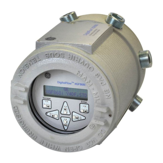
- Page 1 DigitalFlow™ XGF868i Panametrics flare gas flow transmitter Service manual...
- Page 3 DigitalFlow™ XGF868i Panametrics flare gas flow transmitter Service manual 910-198S Rev. C January 2014...
- Page 5 Information paragraphs Auxiliary Equipment Note: These paragraphs provide information that provides a Local safety standards deeper understanding of the situation, but is not essential to The user must make sure that he operates all auxiliary the proper completion of the instructions. equipment in accordance with local codes, standards, regulations, or laws applicable to safety.
- Page 6 Environmental compliance Waste Electrical and Electronic Equipment (WEEE) Directive Baker Hughes-Digital Solutions is an active participant in Europe’s Waste Electrical and Electronic Equipment (WEEE) take-back initiative, directive 2012/19/EU. The equipment that you bought has required the extraction and use of natural resources for its production. It may contain hazardous substances that could impact health and the environment.
-
Page 7: Table Of Contents
Contents Chapter 1. Calibration ..............1 Introduction . - Page 8 Appendix A. Service record ............31 A.1 Introduction .
-
Page 9: Chapter 1. Calibration
Chapter 1. Calibration Introduction Calibrating the XGF868i analog outputs and inputs is explained in this chapter. In addition, testing the optional totalizer, frequency and alarm relay outputs is discussed. The chapter includes the following specific topics: • Calibrating the slot 0 and slot 1 analog outputs •... -
Page 10: Calibrating And Testing The Analog Outputs
Calibrating and testing the analog outputs 1.3.2 Calibrating the low end of the Every XGF868i flowmeter includes two built-in analog outputs (A and B) at terminal block J1, which is designated output range as slot 0. Additional analog outputs may be added to the 1. -
Page 11: Testing Output Linearity
1.3.4 Testing output linearity 1. Scroll to test to test the linearity of the currently values listed in Table 1, check the accuracy and wiring of the selected analog output. Press [enter]. ammeter. Then, repeat the low and high end calibrations. If the analog output still does not pass the linearity test, 2. -
Page 12: Calibrating The Analog Inputs
Calibrating the analog inputs 1.4.2 Accessing the calibration/test menu Analog inputs may be added to the XGF868i by installing an appropriate option card in slot 1. This option card contains 1. From the keypad program, press the right arrow key to two or four analog inputs, which are designated as A, B, C scroll to the calib menu. -
Page 13: Calibrating The Rtd Inputs
Calibrating the RTD inputs RTD analog inputs may be added to the XGF868i by installing an appropriate option card in slot 1. The option card contains two or four RTD inputs that are designated as A, B, C and D. Both the set point and slope point values for each input must be specified prior to use. -
Page 14: Testing The Frequency Outputs
Testing the frequency outputs Frequency outputs may be added to the XGF868i by installing an appropriate option card in slot 1. This option card contains two or four frequency outputs, which are designated A, B, C and D. 1.6.1 Preparing for testing 1.6.2 Testing the output Prepare for the testing procedure by connecting a frequency 1. - Page 15 Figure 3: Calibration menu map...
- Page 16 Figure 4: Option card I/O connections...
-
Page 17: Chapter 2. Error Codes
Chapter 2. Error codes Introduction The XGF868i ultrasonic flow transmitter is a reliable, easy to maintain instrument. When properly installed and operated, as described in the Startup guide, the meter provides accurate flow rate measurements with minimal user intervention. However, if a problem should arise with the electronics enclosure, the transducers or the flowcell, a built-in error code message system greatly simplifies the troubleshooting process. - Page 18 E0: No error E4: Signal quality Problem: No error condition currently exists. Problem: The signal quality is outside the limits programmed in the channelx-set up-signal Cause: This message appears briefly to confirm that submenu of the keypad program. the response to another error message has corrected the problem.
- Page 19 E8: Temperature in E13: Over range Problem: This message indicates a temperature Problem: This error code message indicates that the input error. present measurement exceeds the range of the meter. Cause: The temperature exceeds the specified limits for the analog/RTD inputs option card or no Cause: A internal mathematical overflow has input device is connected.
-
Page 21: Chapter 3. Diagnostics
Chapter 3. Diagnostics Introduction This chapter explains how to troubleshoot the XGF868i if problems arise with the electronics enclosure, the flowcell, or the transducers. Indications of a possible problem include: • Display of an error message on the LCD display screen •... -
Page 22: Displaying Diagnostic Parameters
3.2 Displaying diagnostic parameters The XGF868i has built-in diagnostic parameters to aid in Table 2: Channel options the troubleshooting of flowcell, transducer and/or electrical problems. To access these parameters, use the keypad Option Description program. Then, complete the following instructions to display the desired diagnostic parameter: Channel 1 NOTE: To perform this function with PanaView software... - Page 23 Table 3: Available diagnostic parameters Option bar Description Good Displays the flow velocity. N.A. N.A. VOLUM Displays the volumetric flow. N.A. N.A. +TOTL Displays the forward totalized volume flow. N.A. N.A. -TOTL Displays the reverse totalized volume flow. N.A. N.A. TIME Displays the total flow measurement time.
- Page 24 Table 3: Available diagnostic parameters Option bar Description Good TEMP Displays the gas temperature (from 0/4-20 mA input). N.A. N.A. PRESR Displays the gas pressure (from 0/4-20 mA input). N.A. N.A. Displays the molecular weight. N.A. N.A. Displays the compressibility. N.A.
-
Page 25: Flowcell Problems
3.3 Flowcell problems 3.3.2 Pipe problems If preliminary troubleshooting with the error code messages and/or the diagnostic parameters indicates Pipe-related problems may result either from a failure a possible flowcell problem, proceed with this section. to observe the installation instructions, as described Flowcell problems fall into two categories: in the startup guide, or from improper programming of •... -
Page 26: Transducer Problems
3.4 Transducer problems Ultrasonic transducers are rugged, reliable devices. However, they are subject to physical damage from mishandling and chemical attack. The most common transducer problems are listed below: 1. Leaks: Leaks may occur around the transducer and/or the flowcell fittings. Repair such leaks immediately. -
Page 27: Chapter 4. Parts Replacement
Chapter 4. Parts replacement Introduction The XGF868i has been designed to permit easy on-site upgrades and parts replacement. See Figure 6 on page 26 for details of the standard XGF868i electronics enclosure assembly. The instructions in this chapter, along with a few common tools, are all that is required to perform the following tasks: •... -
Page 28: Removing The Circuit Board Assembly
4.2 Removing the circuit board assembly All parts replacement procedures for the XGF868i require 3. Repeat step 2 to remove the front cover. the removal of the circuit board assembly from the 4. From the rear of the enclosure, disconnect the power line electronics enclosure. -
Page 29: Replacing The Lcd Display/Interconnect Board Subassembly
4.3 Replacing the LCD 4.4 Replacing the fuse display/interconnect board subassembly IMPORTANT This procedure applies only to the fuse on the DC power The LCD display normally provides years of dependable supply. The fuse on the AC power supply is not field- service, but it is easily field-replaceable when necessary. -
Page 30: Replacing The User Program
4.5 Replacing the user program The XGF868i’s user program is stored on an erasable CAUTION! programmable read only memory (EPROM) chip. The The EPROM is easily damaged by static EPROM, which is designated as component U6, is mounted electricity. Before handling the new chip, in a socket on the front of the main circuit board. -
Page 31: Installing An Option Card
4.6 Installing an option card 4.6.1 Attaching an optional heat sink to an The XGF868i flowmeter can accommodate up to two option cards. A communication card may be installed in I/O option card slot 2 and a variety of I/O option cards are available for If you need to attach an optional heat sink to an I/O option installation in slot 1. -
Page 32: Assembling/Installing The Circuit Board Assembly
4.7 Assembling/installing the circuit board assembly Most of the parts replacement procedures described in Table 5: Mating connectors for terminal board this chapter require removal of the circuit board assembly from the electronics enclosure. Furthermore, most of the Terminal board Mating board procedures require varying degrees of disassembly of the circuit board assembly. -
Page 33: Installing The Circuit Board Assembly
4.7.2 Installing the circuit board assembly Be sure that the circuit board assembly is completely The XGF868i is now ready to be placed back into service. assembled, as described in the previous section. Then, Before taking measurements, refer to Chapter 2, Initial setup, of the Startup guide and Chapter 1. - Page 34 Illustration 1 Set screw Set screw Rear cover (solid) Front cover with window Illustration 2 Mounting screw with washer assembly (4 places) Terminal block on slot 2 option card Ground screw Label plate with ground symbol Grounding jumper wire Electronics assembly Illustration 3 Enclosure assembly Figure 6: Model XGF868i electronics console assembly...
- Page 35 Mounting screw and Illustration 4 washer assembly (shown with (3 places) heatsinks removed for LCD display, keypad board clarity) and interconnect board sub-assembly P1 connector P4 connector P2 connector J1 connector J2 connector J4 connector Illustration 5 Screw, lock washer and flat washer (2 places) Keypad board P6 connector...
- Page 36 Illustration 7 P9 connector on terminal board *J7 for AC power connects to J10 connector on main board supply (shown) J2 connector J6 for DC power supply Bracket screw Green grounding jumper P10 connector on terminal board P8 connector on terminal board connects to J9 connector connects to J8 connector on main board...
- Page 37 Screw with washer assembly and mating nut (not shown)(2 places) Illustration 9 I/O heatsink bridge Gap filler (white surface facing the bridge) Screw with washer assembly (3 places) Gap filler (white surface I/O heatsink facing the bridge) Gap filler (white surface facing the I/O Heatsink) Back plate I/O board...
-
Page 39: Appendix A. Service Record
Appendix A. Service record A.1 Introduction Whenever any service procedure is performed on the XGF868i flow transmitter, the details of the service should be recorded in this appendix. An accurate service history of the meter can prove very helpful in troubleshooting any future problems. A.2 Data entry Record complete and detailed service data for the XGF868i in Table 6 below. - Page 40 Table 6: Service record Date Description of service Performed by...
-
Page 41: Diagnostic Parameters
A.3 Diagnostic parameters After a successful initial installation of the XGF868i and whenever any system malfunction is noticed, the values for the diagnostic parameters should be entered in Table 7 below. Table 7: Diagnostic parameters Parameter Initial Current Parameter Initial Current SS up CNTdn... - Page 42 [no content intended for this page]...
-
Page 43: Appendix B. Calibration And Testing With Panaview
Appendix B. Calibration and testing with PanaView Introduction This appendix explains how to calibrate the XGF868i analog outputs and inputs using PanaView™ interface software. In addition, testing the optional totalizer, frequency and alarm relay outputs, and XGM868i hardware and software is discussed. The appendix includes the following specific topics: •... -
Page 44: Accessing The Calibration/Test Menu
B.2 Accessing the calibration/test menu The calibration/test menu is accessed through the new meter browser menu of PanaView software. Use this menu to calibrate and test the slot 0 analog outputs, as well as to calibrate and/or test any option cards that are installed in expansion slot 1. -
Page 45: Calibrating Slot 0 Analog Outputs
B.3 Calibrating slot 0 analog outputs NOTE: If the ammeter reading cannot be adjusted within Every XGF868i flowmeter includes two built-in analog outputs (A and B) at terminal block J1, which is designated 5.0 µA of the 4 or 20 mA setting, contact the factory for as slot 0. -
Page 46: Calibrating Slot 1 Option Cards
B.4 Calibrating slot 1 option cards To calibrate any option card installed in slot 1 of the 3. Double-click on 4 milliamps to calibrate the low end of XGF868i, enter the calibration/test menu as shown in the output range. Figure 10 on page 36. 4. -
Page 47: Analog Inputs
B.4.2 Analog inputs B.4.2a 4 mA option Analog inputs may be added to the XGF868i by installing an appropriate option card in slot 1. This option card Set the calibrated current source to 4 mA. contains two or four analog inputs, which are designated •... -
Page 48: Entering The Set Point
B.4.4 Entering the set point B.4.6 Testing frequency outputs 1. Before proceeding, place the RTD in a temperature Frequency outputs may be added to the XGF868i by bath and allow it to stabilize at the desired set point installing an appropriate option card in slot 1. This option temperature. -
Page 49: Testing The Xgf868I Software And Hardware
B.5 Testing the XGF868i software and hardware In addition to calibration procedures for input and output cards, the calibration/test menu offers tests for XGF868i hardware and procedures for uploading the signal array data and the XGM868i memory contents into PC files for examination. -
Page 50: Uploading The Xgf868I Memory
B.5.2 Uploading the XGF868i memory B.5.3 Testing the XGF868i hardware Using PanaView, you can check crucial elements of the IMPORTANT XGF868i hardware: the EPROM, the NVR, the RAM, FIFO, and the DAC. You can also: This option is for factory use only. •... - Page 51 B.5.3c RAM test B.5.3g DAC test To check the RAM: To test the DAC (digital to analog converter): NOTE: If you are in the hardware test option, skip to NOTE: If you are in the hardware test option, skip to step 2.
- Page 52 7. The program now asks for the Month. Scroll to and NOTE: When you first initialize the XGF868i, the number of double-click on the desired month. LCD parameters is set to OFF. You must program the LCD to display any measured parameters. 8.
- Page 53 Table 10: Available measurement parameters Option Bar Description Good Displays the flow velocity N.A. N.A. VOLUM Displays the volumetric flow N.A. N.A. +TOTL Displays the forward totalized volume flow N.A. N.A. -TOTL Displays the reverse totalized volume flow N.A. N.A. TIME Displays the total flow measurement time N.A.
- Page 54 Table 10: Available measurement parameters Option Bar Description Good TEMP Displays the gas temperature (from 0/4-20 mA input). N.A. N.A. PRESR Displays the gas pressure (from 0/4-20 mA input). N.A. N.A. Displays the molecular weight. N.A. N.A. Displays the compressibility. N.A.
-
Page 55: Appendix C. Factory Tests
Appendix C. Factory tests C.1 Introduction 5. In the PROG menu, scroll to GLOBL and press [enter]. 6. Scroll to I/O and press [enter]. For user security, the XGF868i offers two special functions in 7. Scroll to LCD and press [enter]. a separate menu: selection of one-channel or two-channel 8. - Page 56 Warranty Return policy Each instrument manufactured by Panametrics is If a Panametrics instrument malfunctions within the warranted to be free from defects in material and warranty period, the following procedure must be workmanship. Liability under this warranty is limited to completed: restoring the instrument to normal operation or replacing 1.
- Page 58 Tel: +1 800 833 9438 (toll-free) E-mail: mstechsupport@bakerhughes.com Tel: +1 978 437 1000 E-mail: mstechsupport@bakerhughes.com Panametrics, a Baker Hughes Business, provides solutions in the toughest applications and environments for moisture, oxygen, liquid and gas flow measurement. Experts in flare management, Panametrics technology also reduces flare emissions and optimizes performance.
Need help?
Do you have a question about the DigitalFlow XGF868i and is the answer not in the manual?
Questions and answers