Table of Contents
Advertisement
Quick Links
Advertisement
Table of Contents

Subscribe to Our Youtube Channel
Related Manuals for Baker Hughes Panametrics DigitalFlow XGF868i


Summary of Contents for Baker Hughes Panametrics DigitalFlow XGF868i
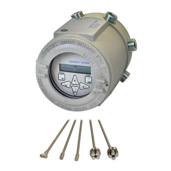
- Page 1 DigitalFlow™ XGF868i Panametrics flare gas flow transmitter Programming manual...
- Page 3 DigitalFlow™ XGF868i Panametrics flare gas flow transmitter Programming manual 910-198P Rev. C February 2015...
- Page 4 [no content intended for this page]...
- Page 5 Information paragraphs Safety issues Note: These paragraphs provide information that provides a WARNING! deeper understanding of the situation, but is not essential to It is the responsibility of the user to make sure the proper completion of the instructions. all local, county, state and national codes, regulations, rules and laws related to safety IMPORTANT: and safe operating conditions are met for...
- Page 6 Environmental compliance Waste Electrical and Electronic Equipment (WEEE) directive Panametrics is an active participant in Europe’s Waste Electrical and Electronic Equipment (WEEE) take-back initiative, directive 2012/19/EU. The equipment that you bought has required the extraction and use of natural resources for its production. It may contain hazardous substances that could impact health and the environment.
-
Page 7: Table Of Contents
Contents Chapter 1. Programming site data ............1 Introduction . - Page 8 Chapter 3. Logging data ............. . . 29 Introduction .
- Page 9 C.6 Entering data in the global menu ............. . . 64 C.6.1 Entering global-system data .
-
Page 11: Chapter 1. Programming Site Data
Chapter 1. Programming site data Introduction Programming methods The XGF868i flow transmitter must be properly installed You can program the XGF868i via either the keypad on the and programmed, as described in the Startup guide, lower part of the glass window, or PanaView™, a PC-based, before it can provide accurate flow rate measurements. -
Page 12: The Xgf868I Keypad
The XGF868i keypad Keypad program Along with the 2-line, 16-character LCD, the XGF868i Six keys on the keypad enable users to program includes a 6-key magnetic keypad. The decal cutout for the XGF868i: each key contains a hall effect sensor, pushbutton switch •... -
Page 13: Activating A Channel
Activating a channel Entering system data for the channel The channelx-ACTIV submenu permits selection of the desired measurement method. In addition, it is used The channelx-system submenu is used to enter to activate/deactivate one or both of the channels in a system parameters for the channel. -
Page 14: Selecting Totalizer Units
1.5.3 Selecting totalizer units 1.5.4 Selecting mass flow units 1. Scroll to the desired totalizer units for a totalized 1. Scroll to the desired mass flow units for the flow rate flow rate display and press [enter]. Table 1 on page 3 display and press [enter]. -
Page 15: Entering Transducer And Pipe Parameters
Entering transducer and pipe parameters 1.6.2 Pipe data Enter the transducer and pipe parameters via the pipe submenu. While following the programming instructions, If either a standard or a special transducer is being used, refer to Figure 28 on page 40. the programming sequence should be rejoined at this point. - Page 16 1.6.2a Path and axial lengths Procedure options 7. To enter the path length: After entering the calibration factor, the XGF868i returns to a. Use the [] arrow key to highlight the path length the channel program. Do one of the following: unit type at the right of the screen.
-
Page 17: Entering Zero Cutoff And Setting Up Inputs
Entering zero cutoff and setting up inputs Enter the zero cutoff value and set up the temperature and actual temperature is used to calculate the pressure inputs via the I/O submenu. While programming standard mass flow rate. these parameters, refer to Figure 28 on page 40. 2. -
Page 18: Entering Setup Data
Entering setup data The signal limits, response times, mass flow and multiple CAUTION! K factors for the XGF868i are specified via the setup The signal default settings are suitable for submenu. The following four submenus are included most applications. Consult with Panametrics in this section: before changing any of these parameters. - Page 19 Table 4: Transducer signal settings Transducer signal Default Range Description parameters value The E6: CYCLE SKIP error message appears when the calculated fluid 0 to 250 ft/s 15 ft/s velocity changes by more than the programmed ACCELERATION LIMIT Acceleration limit (0 to 76 m/s) (5 m/s) value from one reading to the next.
-
Page 20: Initializing Setup Parameters - Default Setup
1.8.2 Initializing setup parameters - 1.8.3 Setting response time - V averaging default setup Use this option to specify the number of readings that occur before the meter will respond to a step change in Use this option to initialize (reset) all of the parameters flow rate. -
Page 21: Using Advanced Features
1.8.4 Using advanced features 1.8.4c Activating mass flow This option enables you to access the more advanced features of the meter. In this option you can do the following: Use this option to calculate mass flow from a static • Enter a table of K factors - to compensate for non-linear fluid density. -
Page 22: Entering Global Data
Entering global data 1.9.1a Selecting volumetric units The global menu is used to enter information that is not specific to either of the individual channels. Information 1. Scroll to the desired volumetric units for the flow rate programmed via this menu is used to compute parameters display and press [enter]. -
Page 23: Setting Up Inputs And Outputs
1.9.1c Selecting mass flow units 1.9.2 Setting up inputs and outputs 1. Scroll to the desired mass flow units for the flow rate Set up the XGF868i inputs and outputs via the I/O submenu. display and press [enter]. The available units for this While following the programming instructions, refer to Figure prompt are determined by the selection made at 30 on page 42 and Figure 31 on page... - Page 24 Procedure options Table 7: Error response options After completing the above steps, the XGF868i returns to the global I/O window. Do one of the following: Option Output response Totalizer response • To continue programming, refer to Appendix A. Menu Maps on page 39, to navigate to the desired menu. Continues to totalize, Holds the last HOLD...
- Page 25 Table 9: Available measurement parameters Option bar Description Good Displays the flow velocity. N.A. N.A. VOLUM Displays the volumetric flow. N.A. N.A. +TOTL Displays the forward totalized volume flow. N.A. N.A. -TOTL Displays the reverse totalized volume flow. N.A. N.A. TIME Displays the total flow measurement time.
- Page 26 Table 9: Available measurement parameters Option bar Description Good PRESR Displays the gas pressure (from 0/4-20 mA input). N.A. N.A. Displays the molecular weight. N.A. N.A. Displays the compressibility. N.A. N.A. AcVOL Displays actual volumetric flow. N.A. N.A. StVOL Displays standard volumetric flow. N.A.
- Page 27 5. Use the arrow keys to enter a value (a temperature 1.9.2f Frequency outputs value for special inputs) for the low end of the analog The frequency output issues a continuous signal with a input range and press [enter]. frequency proportional to the selected measurement. 6.
-
Page 28: Configuring The Communications Port
1.9.3 Configuring the communications port 1.9.3b Setting up MODBUS communications The XGF868i flowmeter is equipped with an RS232 serial interface. The meter can be configured with a When equipped with an optional MODBUS output card, the MODBUS option card for MODBUS communications, a XGF868i can transmit flow data serially to a flow computer, Foundation Fieldbus option card for Foundation Fieldbus or SCADA, using a Gould-type RTU protocol. -
Page 29: Requesting Parameters Using Modbus
1.9.4 Requesting parameters using MODBUS To request specific parameters from the XGF868i via the MODBUS, the control system must enter the appropriate register number. Only registers 1 through 90 are available for MODBUS communications, while registers 508 through 512 are used by the XGF868i to store the MODBUS parameters. - Page 30 Table 10: MODBUS registers for a 2-channel XGF868i MODBUS DPR hex Scaling Description Size in bytes Reg # addr (decimal places) Ch2 std volumetric #Q DIGITS 4 (IEEE 32 bit) Ch2 fwd totals #T DIGITS 4 (2 16 bit int) Ch2 rev totals #T DIGITS 4 (2 16 bit int)
- Page 31 Table 10: MODBUS registers for a 2-channel XGF868i MODBUS DPR hex Scaling Description Size in bytes Reg # addr (decimal places) Avg rev mass totals #MT DIGITS 4 (2 16-bit int) Avg #mass tot digits Avg timer 4 (2 16-bit int) 5Avg error code Avg sound speed 4 (2 16-bit int)
-
Page 32: Exiting The User Program
1.9.5 Activating security 1.10 Exiting the user program In order to prevent unauthorized tampering with the After completing the COMM option, the XGF868i returns to flowmeter’s programming, the XGF868i is equipped with the global program prompt. press [escape] twice to return a security feature that locks all the keys except [prog] to the keypad program, and a third time to return to the meter display. -
Page 33: Chapter 2. Displaying Data
Chapter 2. Displaying data Introduction The OFF setting switches the measurement display off, while the KEY setting enables users to change the measurement display via the arrow keys, without accessing the keypad This chapter explains how to display measurement data program. -
Page 34: Displaying Data On A Computer Terminal
2.3 Displaying data on a computer terminal The flow rate data collected by the XGF868i may be displayed in various formats on a remote computer terminal via the meter’s RS232 serial port. This requires the use of the optional PanaView software. Refer to the instructions below to display data via PanaView. -
Page 35: Graphing The Output
6. If the [continuous] option was selected in step 5 above, 2.3.3 Graphing the output click on the [stop] option button, which has replaced To collect data from the instrument and display it the original [continuous] option button, to terminate graphically in a new format, complete the following steps: data collection. -
Page 36: Displaying Transducer Signals
2.3.2b Graphing data 2.3.3 Displaying transducer signals The PanaView network tree has already been described, and Along with flow rate data, PanaView enables XGF868i users the display pane shows only a graph in the default style with to read and plot transducer signals from the XGF868i. no data points. - Page 37 2.3.3a Reading transducer signals 2.3.3b Plotting transducer signals 3. To read a signal from the meter, click on the [read To plot the selected signal, click on [plot]. A graphical signals] button. (If the meter is a multi-channel window opens, as shown in Figure 8 below. instrument, open the channel drop-down menu and click on the desired channel.) After a moment, the properties window appears similar to Figure 7 below.
-
Page 39: Chapter 3. Logging Data
Chapter 3. Logging data Introduction PanaView can create PC log files for the XGF868i for storage on the PC’s hard drive. This chapter explains how to use the XGF868i data logging capability with PanaView. 3.2 Logging with PanaView PanaView is capable of creating and viewing log files of the following types: •... -
Page 40: Creating Meter Logs
3.3 Creating meter logs To create a new meter log, complete the following steps: d. Type the desired log message in the right window, and click [next item]. 1. From the new meter browser in PanaView, expand the network tree and open the edit functions option e. -
Page 41: Creating An Error Log
each parameter, type the desired number in the • If you select edit, PanaView asks first for the desired right window, (or scroll to and click on the desired year, then for the month, and finally for the day. For month) and click [next item] (or simply click [next each parameter, type the desired number in the item] to step through the parameters). -
Page 42: Creating Pc Logs
3.4 Creating PC logs PC logs are created in a different menu from the meter logs 3. Double click on PC logs to advance to the dialog box described in the last section. To create a new PC log: shown in Figure 16. below. 1. -
Page 43: Viewing Meter Log Files
NOTE: Start time and stop time cannot be specified NOTE: To add all the channel parameters to a given log, for PC logs. These options are inactive in the right-click on the desired channel. A pop-up button, PC log window. “add group to log,”... -
Page 44: Viewing Pc Log Files
3.6 Viewing PC log files After one or more PC log files have been created, the logs You can monitor the progress of an ongoing log in several may be viewed by using PanaView as follows: ways: 1. You can access PC logs in two ways: •... -
Page 45: Chapter 4. Printing Data
Chapter 4. Printing data Data types for printing The XGF868i flowmeter has no ability to print any of its data directly. However, any of the data stored in its memory may be printed via the built-in RS232 communications port, using a computer terminal. In order to use the capability, the XGF868i must be linked to the computer terminal with the optional PanaView software. - Page 46 [no content intended for this page]...
-
Page 47: Chapter 5. Clearing Data
Chapter 5. Clearing data Introduction This chapter explains how to purge totalized measurements, site data and/or log files from the XGF868i memory. NOTE: For detailed information on creating a log file, see Chapter 3. Logging data on page 29. For detailed information on programming site data, see Chapter 1. -
Page 48: Clearing The Xgf868I Memory
5.2 Clearing the XGF868i memory If the XGF868i available memory becomes nearly full, it may be necessary to purge some or all of the existing data from memory, before any additional data can be stored. In order to accomplish this task, proceed to the appropriate section for step-by-step instructions. -
Page 49: Appendix A. Menu Maps
Appendix A. Menu maps The following Menu Maps are included in this appendix: • Figure 28 on page 40, “PROG > CHx > ACTIV, SYSTM, PIPE & I/O Menus” • Figure 29 on page 41, “PROG > CHx > SETUP Menu” •... - Page 50 Figure 28: PROG > CHx > ACTIV, SYSTM, PIPE and I/O menus...
- Page 51 Figure 29: PROG > CHx > SETUP menu...
- Page 52 Figure 30: PROG > GLOBL > SYSTM, I/O and COMM menus...
- Page 53 Figure 31: PROG > GLOBL > I/O > OPTIONS menu...
-
Page 55: Appendix B. Data Records
Appendix B. Data records Available option cards The XGF868i can hold one option card in slot 1 and one in slot 2. The available configurations are listed in Table 12 below. Table 12: Option card configurations Card # Slot # Configuration 1473-02 OI - 2 current inputs... -
Page 56: Setup Data
B.3 Setup data After the XGF868i flow transmitter has been installed, setup data must be entered via the user program prior to operation. record that information in Table 14 below. Table 14: Setup data General information Model # Serial # Software version Setup date Channel - status... - Page 57 Table 14: Setup data Channel - pipe parameters Channel 1 Channel 2 Transducer type SPEC Transducer type Transducer # Transducer # Spec. trans. freq. Spec. trans. freq. Spec. trans. Tw Spec. trans. Tw Pipe O.D. Pipe O.D. Pipe wall Pipe wall Path length (P) Path length (P) Axial length (L)
- Page 58 Table 14: Setup data Channel - SETUP - advanced features - multi K factors K-factor # Velocity K-factor K-factor # Velocity K-factor...
- Page 59 Table 14: Setup data Channel - SETUP - advanced features - mass flow calculation Mass flow Mass flow Density type Fluid dens. Mol. wt. Density type Fluid dens. Mol. wt. or Q Actual Standard or Q Actual Standard Fluid density Fluid density Mole.
-
Page 61: Appendix C. Programming The Xgf868I With Panaview
Appendix C. Programming the XGF868i with PanaView™ C.1 Introduction The XGF868i flow transmitter must be properly installed and programmed, as described in the Startup guide, before it can provide accurate flow rate measurements. After completing the installation and initial setup, use this chapter to program the advanced features of the model XGF868i’s via the PanaView™... -
Page 62: Programming With Panaview
C.2 Programming with PanaView™ You can program the XGF868i with PanaView™, a Panametrics PC-based, non-resident software program that communicates with the XGF868i via its RS232 serial port. C.2.1 Preparing for PanaView programming Before you attempt to communicate with the XGF868i, be sure you have linked your PC to the XGF868i via an RS232 interface. -
Page 63: Setting Up Ethernet Communications
C.2.3 Setting up Ethernet communications C.2.4 Modifying Ethernet parameters If you have selected TCP/IP in step 6 on the previous page, To establish Ethernet communications with the XGF868i the setup communications window appears similar to or to modify its IP parameters, you will need to install the Figure 34 below. -
Page 64: Adding The Xgf868I
C.3 Adding the XGF868i To add the XGF868i on the IDM-configured communications If the initialization is successful, the meter browser shows a port, complete the following steps: listing similar to Figure 37 below. 1. Highlight the communication port to which the meter will be added by clicking on it, and then open the edit menu on the menu bar (if the communication port is not highlighted first, the new meter option is not... -
Page 65: Entering The User Program Using Panaview
C.4 Entering the user program using PanaView NOTE: Be sure to record all the programming data entered in this chapter in Appendix B. Data records on page 45. Programming of the status, system, and pipe submenus of the channel menu and the global-system menu are required for basic operation of the XGF868i. - Page 66 Figure 43: Site edit menu with current Settings Figure 42: Pipe parameters option in the site edit menu 6. When you have completed entering parameters in c. Do one of the following: a given option, click [exit page] to close the option. Click on [next item] to proceed to the next menu item, You can then double-click on another option, or click [close] to close the window.
-
Page 67: Entering Data In The Channel Menu
C.5 Entering data in the channel menu C.5.2 Entering data in the channel system The channel menu is used to enter data specific to each channel. Refer to Figures D-1 through D-3 in Appendix option D. PanaView menu maps for the XGF868i on page 79, and 1. -
Page 68: Entering Pipe Parameters
C.5.2a Programming the mass flow option C.5.3 Entering pipe parameters 1. Double-click on the desired mass flow units for flow rate Enter the transducer and pipe parameters via the pipe display (listed in Table 16 below). submenu. While following the programming instructions, see Figure 55 on page 80 of Appendix D, PanaView menu maps. - Page 69 C.5.3b Pipe OD C.5.3c Path and axial lengths 4. Click on the appropriate pipe OD unit type in the 6. Click on the appropriate path length unit type in the center pane from the list shown in Table 17 below. center pane.
-
Page 70: Entering Input/Output Parameters
C.5.4 Entering input/output parameters C.5.4c Base temperature Enter the zero cutoff value and set up the temperature, pressure and quality inputs via the input/output submenu. 1. Enter the base temperature and click [next item]. While programming these parameters, refer to Figure 55 on The ratio of this value to the actual temperature is page 80 of Appendix D, PanaView menu maps. -
Page 71: Entering Setup Parameters
C.5.5 Entering setup parameters C.5.5a The signal option Use this option to set the limits for the incoming signal The signal limits and response times for the XGF868i are and other parameters affecting the transducer signal. For specified via the SETUP submenu. While following the example, the programmed signal strength low limit may programming instructions, refer to Figure 57 on page be used to determine the trigger point for an alarm. - Page 72 Table 18: Transducer signal settings Transducer signal Default Range Description parameters value The amplitude discriminator measures the transducer signal received by the model XGF868i. The default value for the above parameter is 14, and values from 0 to 100 are acceptable. The Amplitude 0 to 100 E5: AMPLITUDE error message appears when the amplitude...
- Page 73 C.5.5b The default setup option 4. Double-click on yes to edit the K-factor table or on no to retain the current K-factor table (and return to Use this option to initialize (reset) all of the parameters the advanced features window). within the set up signal menu back to their default values.
-
Page 74: Entering Data In The Global Menu
C.6 Entering data in the global menu C.6.1a Volumetric units The global menu is used to enter information that is not specific to any of the individual channels. Information 1. Double-click on the desired volumetric units for the flow programmed via this menu is used to enter several general rate display. -
Page 75: Setting Up Inputs And Outputs
C.6.1c Programming mass flow data C.6.2 Setting up inputs and outputs 1. Double-click on the desired mass flow units for flow rate Set up the XGF868i inputs and outputs via the I/O submenu. display. The options are listed in Table 20 below. While following the programming instructions, see Figure 58 on page 83 in Appendix D, PanaView menu maps. - Page 76 Table 21: Error options and responses for a one-channel meter Option Output response Totalizer response Hold last value Holds the last “good” reading Holds the last “good” reading and continues to totalize, based on that reading Force low Forces the outputs to the low set point Stops totalizing Force high Forces the outputs to the high set point...
- Page 77 C.6.2c Setting up option cards The XGF868i has two built-in analog outputs, which are Table 24: Channel options assigned to slot 0. Also, a variety of input/output option cards may be installed in slot 1. See Chapter 1, Installation, Option Description of the Startup Guide for a complete description of the available option cards.
- Page 78 Table 25: Available measurement parameters Option bar Description Good Velocity Displays the flow velocity. N.A. N.A. Volumetric Displays the volumetric flow. N.A. N.A. FWD total Displays the forward totalized volume flow. N.A. N.A. REV total Displays the reverse totalized volume flow. N.A.
- Page 79 Table 25: Available measurement parameters Option bar Description Good DN +- peak Displays signal peaks for the downstream transducer. 100-2300 <100 or >2300 Temperature Displays the gas temperature (from 0/4-20 mA input). N.A. N.A. Pressure Displays the gas pressure (from 0/4-20 mA input). N.A.
- Page 80 7. Enter the units of measurement for input A and click 6. Enter a flow rate value for the full (high) end of the [next item]. frequency output range and click [next item]. 8. Enter a temperature value for the base (low) end 7.
-
Page 81: Entering Communications Data
C.6.3 Entering communications data The XGF868i flowmeter is equipped with an RS232 serial NOTE: The XGF868i MODBUS communication settings interface. The serial port is used to transmit stored data and chosen in the next four steps must match those of the displayed readings to a personal computer by connecting MODBUS control system. - Page 82 Table 27: MODBUS registers MODBUS DPR hex MODBUS Description Scaling (decimal places) Size in bytes reg # addr reg # Ch1 rev totals #T DIGITS 4 (2 16 bit int) Ch1 #tot digits Ch1 mass flow #M DIGITS 4 (IEEE 32 bit) Ch1 Fwd mass totals #MT DIGITS 4 (2 16-bit int)
- Page 83 Table 27: MODBUS registers MODBUS DPR hex MODBUS Description Scaling (decimal places) Size in bytes reg # addr reg # Ch2 Fwd mass totals #MT DIGITS 4 (2 16-bit int) Ch2 rev mass totals #MT DIGITS 4 (2 16-bit int) Ch2 #mass tot digits Ch2 timer 4 (2 16-bit int)
- Page 84 Table 27: MODBUS registers MODBUS DPR hex MODBUS Description Scaling (decimal places) Size in bytes reg # addr reg # Avg timer 4 (2 16-bit int) 5Avg error code Avg sound s speed 4 (2 16-bit int) 2MODBUS baud rate Notes: 1.
-
Page 85: Exiting The Site Edit Menu
C.7 Exiting the site edit menu After leaving the global submenu, PanaView returns to the site edit menu. Click [close] to exit the site edit menu. Then proceed to Chapter 3, Operation, of the Startup guide for instructions on taking measurements, or refer to the appropriate chapters of this manual for detailed instructions on using the other features of the XGF868i flow transmitter. -
Page 86: Saving Site Data
C.9 Saving site data The XGF868i holds setup parameters for a single internal site, called Working. Through PanaView, users can store site file data in a PC and reload it into the XGF868i. To save or reload site data via PanaView: 1. -
Page 87: Saving New Site Data To The Xgf868I
C.9.2 Saving new site data to the XGF868i C.9.4 Clearing a site from the meter To save new site data to the meter: As the XGF868i has only one site loaded (working) at any time, it is not possible to remove this site. To change site 1. -
Page 89: Appendix D. Panaview Menu Maps For The Xgf868I
Appendix D. PanaView menu maps for the XGF868i The following PanaView menu maps are included in this appendix: • Figure 55 on page 80, “PanaView prog > CHx > ACTIV, SYSTM, PIPE & I/O menus • Figure 56 on page 81, “PanaView prog > CHx > SETUP menu,”... - Page 90 Figure 55: PanaView PROG > CHx > ACTIV, SYSTM, PIPE and I/O menus...
- Page 91 Figure 56: PanaView PROG > CHx > SETUP menu...
- Page 92 Figure 57: PanaView PROG > GLOBL > SYSTM, I/O and COMM menus...
- Page 93 Figure 58: PanaView PROG > GLOBL > I/O > OPTIONS menu...
-
Page 95: Appendix E. Foundation Fieldbus Communications
Appendix E. Foundation fieldbus communications Introduction Foundation fieldbus provides a means of communicating with the flowmeter. The patent numbers which apply are 5,909,363 and 6,424,872. This foundation fieldbus device supports six analog input (AI) blocks, which can be configured to supply the network measurements shown in Table 28 below. -
Page 96: Configuration Utility Setup
E.2 Configuration utility setup E.3 Selecting the desired measurements The following is an example setup using National Instruments Configuration Utility v3.1. To set the measurement unit for each AI: Figure 59 below shows the configuration utility with a 1. Double click on the FLOW transducer block (in the tree flowmeter on the network (Panametrics flow-XGF). -
Page 97: Selecting Units For Ai Blocks
E.4 Selecting units for AI blocks E.5 Resetting instrument totalizers To select the units for the individual AI blocks: To reset the instrument totalizers: 1. Double click on the AI block for which you wish to set 1. Double click on the FLOW transducer block (in the the units (ANALOG_INPUT_1 or ANALOG_INPUT_2 in the tree under GEFlow-XGF;... -
Page 98: Function Block Application
E.6 Function block application Figure 63 below is an example setup using the function block application editor. The flowmeter AI blocks, along with the AO and PID of another device on the network, are displayed. We have connected the AI_1 OUT of the flowmeter to the CAS IN of the AO block. - Page 99 Warranty Return policy Each instrument manufactured by Panametrics is If a Panametrics instrument malfunctions within the warranted to be free from defects in material and warranty period, the following procedure must be workmanship. Liability under this warranty is limited to completed: restoring the instrument to normal operation or replacing 1.
- Page 100 Tel: +1 800 833 9438 (toll-free) E-mail: mstechsupport@bakerhughes.com Tel: +1 978 437 1000 E-mail: mstechsupport@bakerhughes.com Panametrics, a Baker Hughes Business, provides solutions in the toughest applications and environments for moisture, oxygen, liquid and gas flow measurement. Experts in flare management, Panametrics technology also reduces flare emissions and optimizes performance.
Need help?
Do you have a question about the Panametrics DigitalFlow XGF868i and is the answer not in the manual?
Questions and answers