Table of Contents
Advertisement
Quick Links
Advertisement
Table of Contents

Related Manuals for Baker Hughes Panametrics HygroPro


Summary of Contents for Baker Hughes Panametrics HygroPro
- Page 1 HygroPro User’s manual 916-099 Rev. D...
- Page 3 HygroPro Moisture transmitter User’s manual 916-099 Rev. D November 2012...
- Page 4 [no content intended for this page - proceed to next page]...
-
Page 5: Table Of Contents
Contents Product registration ................. vii Services . - Page 6 3.3.7 Evaluating the cleaned probe ................18 Chapter 4: Specifications .
-
Page 7: Product Registration
Product registration Typographical conventions Thank you for purchasing a HygroPro moisture transmitter Note: These paragraphs provide information that provides from Panametrics. Please register your product at https:// a deeper understanding of the situation, but is not essential info.bakerhughesds.com/New-product-registration-LP. to the proper completion of the instructions. html product support such as the latest software/firmware upgrades, product information and special promotions. -
Page 8: Auxiliary Equipment
Auxiliary equipment Environmental compliance Local safety standards RoHS The user must make sure that he operates all auxiliary The HygroPro moisture transmitter fully complies with RoHS equipment in accordance with local codes, standards, regulations (Directive 2011/65/EU). regulations, or laws applicable to safety. Waste Electrical and Electronic Equipment (WEEE) directive Working area Panametrics is an active participant in Europe’s Waste... -
Page 9: Chapter 1: Installation
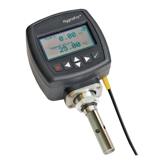
Chapter 1: Installation Introduction The HygroPro moisture transmitter is a compact, intrinsically-safe, loop-powered, 4-20 mA transmitter that provides accurate dew/frost point measurements over a range of –110° to 20°C (-166° to 68°F). It features an integrated display and a six-button keypad, and it is housed in an IP67/Type 4X enclosure. -
Page 10: Sample System Guidelines
Sample system guidelines The HygroPro transmitter can be installed in a sample Before constructing a sample system, consult a Panametrics system or directly in the process line. However, Panametrics application engineer and observe the following guidelines: recommends that the unit be installed in a sample •... -
Page 11: Mounting The Transmitter
Mounting the transmitter 1. Make sure the sintered or stainless-steel shield is in CAUTION! place over the sensor. This shield protects the aluminum If the HygroPro will be installed directly oxide sensor from damage during operation. into the process line, consult Panametrics 2. -
Page 12: Wiring The Transmitter
Wiring the transmitter 1.4.1a Standard connections - without a PC Proceed to the appropriate section for instructions on: • Standard wiring connections (below) IMPORTANT • "Hazardous area wiring connections" on page 6 To install the HygroPro in a hazardous (classified) area, see "Hazardous area wiring connections"... - Page 13 1. Connect an RS485-RS232 converter (customer-supplied) to an available serial port on the PC. 2. Push the female connector end of the factory-supplied cable into the mating male connector on the transmitter module. Make sure the pins are properly aligned. Then, secure the connectors together by sliding the metal sleeve on the cable over the connectors and turning it clockwise until it is tight.
-
Page 14: Hazardous Area Wiring Connections
1.4.2 Hazardous area wiring connections Before installing and using the HygroPro in a hazardous Note: It is the installer’s responsibility to follow all applicable (classified) area, be sure to read and understand all standards and procedures. applicable reference materials. This includes: WARNING! •... - Page 15 1.4.2a Applicable standards and directives 1.4.2b Compliance requirements When the HygroPro is installed in hazardous areas with The HygroPro installation must comply with EN 60079-14 potentially explosive atmospheres, it complies with the ATEX in Europe and with the National Electrical Code (ANSI/NFPA directive 2014/34/EU, the EU standards listed in Table 3 below, 70) or part one of the Canadian Electrical Code (C22.1), as and the North American FM/CSA and IEC standards listed in...
- Page 16 1.4.2d Requirements for external devices 1.4.2e Special conditions for safe operation When connecting the HygroPro to external devices, the The “X” at the end of the HygroPro ATEX certificate number, allowable total load capacitance and inductance for Bas06ATEX0019X, indicates that special conditions are those devices are listed in the manufacturer’s datasheets.
-
Page 17: Chapter 2: Operation
Chapter 2: Operation Powering up and programming After the HygroPro has been installed as described in chapter 1, installation, power may be applied to the unit. The transmitter requires up to 60 seconds to initialize and begin normal operation. The unit will meet its specified accuracy within 3 minutes. -
Page 18: Menu Map
2.1.1 Menu Map [escape] - [enter] - [escape] Startup screen unlock - [enter] * Factory-level passcode is required Passcode Lock keypad Lock menus Passcode Lock keypad Lock menus to access the Service menu. Const # of views Display Display Calibrate Const pressure Node ID RS485... -
Page 19: Basic Setup
2.2 Basic setup The HygroPro transmitter is easily programmed to meet the user’s requirements by referring to the menu map in "Figure 8" on page 10 and following the instructions in this section. 2.2.1 Unlocking the display 2.2.3 Selecting measurement parameters Upon startup, the following screen appears on the To select the measurement parameters, complete the HygroPro display:... -
Page 20: Setting Up The Display
2.2.5 Setting up the analog output If the number of decimal places is acceptable, To set up the analog output, complete the following steps: press escape. To change the number of decimal After entering your places, press enter. password, use the right arrow key to scroll to output and press enter. -
Page 21: Entering The Node Id
2.2.7 Setting up the RS485 output Enter the zero and span values for the range, To set up the RS485 output, complete the following steps: using the same procedure on the previous page. Enter your passcode to access the setup program. Then use the arrow keys to select the RS485 menu. -
Page 22: Advanced Setup
2.3 Advanced setup The following sections describe the procedures for completing the configuration of your HygroPro transmitter. 2.3.1 Setting up the pressure/temperature 2.3.2 Entering sensor calibration data displays Enter your password and The following steps set the displayed pressure and use the arrow keys to scroll temperature values to live (changing with the current to calibrate. -
Page 23: Locking And Unlocking The Keypad
Repeat the above process to enter any available press curve 2.3.4 Locking and unlocking the menus and CS table data points. To lock the menus to prevent them from being changed, Note: The CS table is required only if ppmw measurements enter the user program as described on page 26. -
Page 24: Chapter 3: Service And Maintenance
Chapter 3: Service and maintenance The service menus 3.2 Moisture probe error conditions IMPORTANT IMPORTANT The service menus are accessible only by using the All moisture probes require periodic cleaning to maintain factory-level passcode. optimum accuracy. Consult the Panametrics service center for the recommended probe cleaning interval for your application. -
Page 25: Cleaning The Moisture Probe
3.3 Cleaning the moisture probe To clean your HygroPro moisture probe, carefully follow the instructions in this section. 3.3.1 Preparing to clean the probe 3.3.4 Removing the probe from the transmitter To remove the probe from the transmitter, refer to "Figure 9" CAUTION! on page 17 and proceed as follows: Be sure to perform the probe cleaning... -
Page 26: Cleaning The Sensor And The Shield
3.3.5 Cleaning the sensor and the shield 3.3.6 Installing the probe in the transmitter To install a new or cleaned probe in the transmitter, CAUTION! complete the following steps: Do not place the transmitter module into the 1. Reconnect the probe cable to the top of the probe by solvents. -
Page 27: Chapter 4: Specifications
Chapter 4: Specifications General 4.3 Mechanical Dew point/frost point calibration range Sample connection • 68° to –112°F (20° to –80°C) • 3/4-16 (19 mm) straight male thread with o-ring • G ½ with optional adapter Operating temperature: Operating pressure • –4° to 140°F (–20° to 60°C) •... -
Page 28: Built-In Temperature Sensor
4.5 Built-in temperature sensor 4.7 Certifications Type European compliance • Nonlinear NTC thermistor (resultant temperature Complies with EMC Directive 2014/30/EU and PED 2014/68/EU linearized by microprocessor) for DN<25 Measurement range • –22° to 158°F (–30° to 70°C) Accuracy • ±0.9°F (±0.5°C) overall Response time (maximum) •... - Page 29 Warranty Return policy Each instrument manufactured by Panametrics is If a Panametrics instrument malfunctions within the warranty warranted to be free from defects in material and period, the following procedure must be completed: workmanship. Liability under this warranty is limited to 1.
- Page 30 Oil & Gas; Energy; Healthcare; Water and Wastewater; Chemical Processing; Food & Beverage and many others. Join the conversation and follow us on LinkedIn linkedin.com/company/panametricscompany Copyright 2021 Baker Hughes Company. All rights reserved. 916-099 Rev. D panametrics.com BHCS38985 (07/2021)
Need help?
Do you have a question about the Panametrics HygroPro and is the answer not in the manual?
Questions and answers