
Related Manuals for Toshiba TLP561


Summary of Contents for Toshiba TLP561
- Page 1 FILE NO. 333-200206 SUPPLEMENT SERVICE MANUAL 3LCD PROJECTOR TLP-560/561 TLP-260/261 — SUMMARY — This service manual covers only different portions from service manual (File No. 330-200103) for TLP55/25 series. Document Created in Japan May.,2002...
- Page 2 23553721 23553721 23553721 Front Tag TLP561 A303 23553858 23553858 23553858 Label Rating TLP561 A320 23553725 23553725 23553725 Label Carton Box TLP561 Y200 23565648 23565648 23565648 Owner’s Manual CD-ROM --------- --------- Y201 23565649 Owner’s Manual E/F --------- --------- Y202 23565650 Owner’s Manual SPA...
- Page 3 Difference parts list (TLP26 Series) Location Part No. Part No. Part No. (US) (EU) (UK) Description E200 23405140 23405140 23405140 Optical Engine E260S 23405111 23405111 23405111 Optical Main Frame E261S 23405071 23405071 23405071 Optical Sub Frame U001 23787668 23787668 23787668 PC Board MAIN U002...
- Page 4 T O S H I B A C O R P O R A T I O N 1- -1, SHIBAURA 1- - CHOME, MINATO - - KU, TOKYO 105 -- 8001, JAPAN...
- Page 5 FILE NO. 330-200103 SUPPLEMENT SERVICE MANUAL 3LCD DATA PROJECTOR TLP-250/251/250C/251C TLP-550/551/550C/551C...
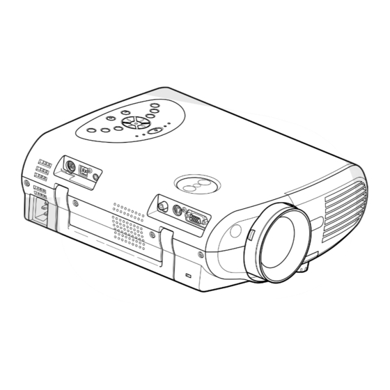
- Page 6 SECTION 1 PART REPLACEMENT AND ADJUSTMENT PROCEDURES 1. LOCATION OF MAIN PARTS LAMP HOUSING E200: OPTICAL ENGINE SPEAKER BL Z101: EXHAUST FAN LCD BLOCK P800: POWER SUPPLY : BALLAST POWER SUPPLY E201A: PROJECTION LEN Z100: INTAKE FAN 2. LOCATION OF PC BOARD U001: MAIN PC BOARD U003: SWITCH PC BOARD U002: SENSOR PC BOARD...
- Page 7 CAUTIONS BEFORE SERVICING Electronic parts are susceptible to static electricity and may easily be damaged, so do not forget to take proper grounding treatment as required. Many screws are used inside the unit. To prevent missing, dropping, etc. of the screws, always use a magnetized screwdriver in servicing.
- Page 8 3-2. Top Cover Step Figure Explanation [Left Side] Remove 3 screws (M3 x 6). Screw : type [M-1] [Right Side] Remove 6 screws (M3 x 6). Screw : type [M-1] [Front] Slide front cover to the right. Remove front cover. Remove 1 screw (M3 x 6).
- Page 9 3-2. Top Cover (Continued) Step Figure Explanation [Rear] Remove 1 screws (M2 x 6). Screw : type [M-1] Top cover can be removed by lifting left edge.
- Page 10 3-3. Main PC Board Step Figure Explanation Remove lens shift dial. Remove all cables and connectors. Remove 5 screws (M3 x 6). Screw : type [M-1] Remove 1 screws (M3 x 6). Screw : type [M-1] [Note] The screw here is also fixing the grand wire.
- Page 11 3-3. Main PC Board (Continued) Step Figure Explanation Remove 2 screws (M3 x 6). Screw : type [M-1] Remove 2 screws (M3 x 8). Screw : type [M-10] Remove metal plate.
- Page 12 3-4. Optical Engine Step Figure Explanation Remove 1 screw (M3 x 6)..A Screw : type [M-1] Remove 2 screws (3 x 8)..B Screw : type [M-2] Remove 2 screws (3 x 8) Screw : type [M-2] Remove Thermal switch. Remove metal plate. Remove 2 screws (3 x 8) Screw : type [M-2]...
- Page 13 3-4. Optical Engine (Continued) Step Figure Explanation Remove lamp housing. Remove 3 screws (M3 x 15). Screw : type [M-4]...
- Page 14 3-4. Optical Engine (Continued) Step Figure Explanation Remove 3 screws (M3 x 8) . Screw : type [M-2] Separate the main frame and sub frame from the engine block. Sub frame Sub fram Main frame...
- Page 15 3-5. MULTI-PBS (Polarizing Beam Splitter) Step Figure Explanation Remove 3 screws (M3 x 15) ..A Screw : type [M-8] Remove 1 screws (M2.5 x 15) ..B Screw : type [M-9] Press the Multi-PBS up from cooling space. Remove the Multi-PBS. [Note] Make sure the direction of the PBS when you install.
- Page 16 3-6. Polarized Plate Step Figure Explanation Remve the one screw. Remove the stopper. Remove the holder and polarized plate. Panel Side polarizer film polarizer film polarizer film [Note] The film side must be faced to the LCD panel when installing and the color must be related with the color of LCD panel.
- Page 17 3-7. Intake Fan Step Figure Explanation Remove 2 screw (3 x 8). Screw : type [M-2] Remove intake fan block from the bottom cabinet.( It pulls up along with a rail. ) Rail Remove filter block from the bottom cabinet. The filter is split like this.
- Page 18 3-7. Intake Fan (Continued) Step Figure Explanation Remove 2 screw (3 x 47). Screw : type [M-5] The Intake fan block is split like this. 1-13...
- Page 19 3-8. Exaust Fan Step Figure Explanation Remove 1 screw (3 x 8). Screw : type [M-2] Remove intake fan block from the bottom cabinet.( It pulls up along with a rail. ) Rail Remove 2 screws (3 x 15). Screw : type [M-6] The exaust fan block is split like this.
- Page 20 3-9. Speaker Block Step Figure Explanation Remove 2 screws (3 x 8). Screw : type [M-2] Remove 1 screw (3 x 8). The speaker will be removed like this. Screw : type [M-2] 1-15...
- Page 21 3-10. Switch PC Board Step Figure Explanation Remove 1 screws (3 x 8). Screw : type [M-2] [Note] The safety interlock switch is pushed when the lamp cover is replaced. Switch Switch Switch Lamp Cover Lamp Cover Lamp Cover 1-16...
- Page 22 3-11. Power Supply Step Figure Explanation Disconnect the cable from the AC inlet. A : Remove 1 screw (M3 x 5). Screw : type [M-3] B : Remove 1 screw (3 x 8). Screw : type [M-2] Remove 1 screw (3 x 8). Screw : type [M-2] Lift up back side of the power unit .
- Page 23 3-11. Power Supply (Continued) Step Figure Explanation Remove 2 screws (3 x 8) Screw : type [M-2] Remove EMC filter unit. 3-12. Ballast power Supply Step Figure Explanation Remove black tape. Remove 2 hooks in the direction of this arrow. 1-18...
- Page 24 3-12. Ballast power Supply (Continued) Step Figure Explanation Lift up the main power supply unit. Disconnect the power supply cable and cntrol cable. Release 4 P.C. board holder. Release P.C. board holder by using tweezers. Ballast power supply block is split like this. 1-19...
- Page 25 3-13. PCB Holder Step Figure Explanation Remove 1 screw (3 x 8). Screw : type [M-2] 3-14. Document camera (How to remove from the main body) Step Figure Explanation Remove 5 screws (M3 x 6). Screw : type [M-1] [Note] Please remove the screw (A) last.
- Page 26 3-15. Screws for Mechanical Patrs Type Form Size Location Top Cover (11), Main PCB (8), Document camera (5) and Lamp House (1) M3 x 6 Power Supply and Ballast Power Supply (4), Ballast cable connector (2), Intake FAN (4), 3 x 8 Switch PCB(1), Lamp House(5), Exhaust FAN (1), Optical Engine(3), Speaker Block (3) and PCB Holder(1) Power Supply Earth Wire(1)
- Page 27 3-16. How to disconnect FFC/FPC Connector Step Figure Explanation Conformity of Location number. MAIN PCB: PJ701 Hook Release Two hooks. [Note] Hooks stop on the way. Please do not pull out by superfluous power.) FFC/FPC cable can be disconnected. Electrodes (up side) Electrodes (up side) Electrodes (up side) 1-22...
- Page 28 4. ELECTRICAL ADJUSTMENT 4-1. Preparation (2) Shading adjustment software < Test Equipments and Jigs > When the shading adjustment software Personal computer (Windows P/C, OS:windows 95/98) (FieldAdjust.exe) is started, screen like the following Adjustment software image (Fig. 1-4-2) appears. (SINGO98.exe, FieldAdjust.exe) RGB cable, Serial control cable (for RS-232C) <...
- Page 29 1-2 Save the original shading data to PC 4-2. Shading adjustment software (1) Select [Save] from [File] menu. 1. When DRIVE PCB is exchanged. Step1. Get shading data from old Drive PCB. Step2. Save the data to PC memory. Step3. Exchange the Drive PCB. Step4.
- Page 30 (2) Press [Yes] button. 2. When LCD Panels are exchanged. Step1. Adjust the VCOM data (front and celing) . This adjustment makes the flicker of a panel into the minimum. Step2. Adjust the Shading data. Step3. Set the new data to the Projector. 2-1 Adjust the VCOM data (1) Select [Built in Signal] from [Check] menu.
- Page 31 (4) Select [Front] button first, and select R,G or B (8) Change the internal signal patern. button. Set the white level 50% and press [OK] button. (When you adjust the R level, then select R-VCOM (9) Select [Front] button, and select [NRSH] button. (5) Push [+1] or [-1] button, change data and look for the point with which a flicker serves as the minimum.
- Page 32 2-2 Adjust the shading data Note: (1) Select adjusting color (Red/Green/Blue) You must change the builtin signal level corresponding form the [Setting] menu. to the chosen level. Max : 75% Mid1 : 50% Mid2 : 26% Min : 11% Example: If you select [Mid1], set the builtin signal level 40%.
- Page 33 2-3 Set the shading data to the projector (5) Select [Set] from the [Projector] menu. (1) Select [Data Save] form the [Projector] menu. (6) After sending the all data, the following mesage (2) Push [Save] button. appired. Click the [OK] button. (7) The same adjustment is made in othe colors and each four levels.
- Page 34 SECTION 2 SERVICING DIAGRAMS 1. TROUBLE SHOOTING CAUSE CHECK POINT CHEK ITEM JUDGE (NG) → Power supply is NG. Flat cable of Power supply Standby voltage (disconnect PJ003) (See page 2-3) (OK) → Check next step. Power is not on (NG) →...
- Page 35 2. LED DISPLAY (Problems Shown on LED Indicator Combination) Status of Indicator Light Error Cord Cause and Trouble Solution TEMP LAMP Check the power unit. Standby-power is not on > There's a problem with the Check the connector. power unit or system (OFF) (OFF) (OFF)
- Page 36 3. WIRING BLOCK DIAGRAM SENCOR PC BOARD INTAKE FAN PJ00 4 PJ00 1 INTAKE FAN CN 1 02 PJ 9 01 CN 1 01 MAIN PC BOARD PJ 6 61 PJ00 5 PJ30 2 EXAUST FAN PJ300 RELAY PC BOARD LED PC BOARD CAMERA PC BOARD...
- Page 37 4. CONNECTOR PIN ASSIGNMENT PJ001 (MAIN) INTAKE FAN PJ010 (MAIN) LAMP DRIVER 1 FAN4 CONTROL V +6 to +12V 1 LAMP-ERROR 0V(Normal)/5V(Error) 2 GND 2 GND 3 FAN4 PULSE +3.3V(Pulse) 3 FAN+5V 3 LAMP-PWR 0V(ON)/5V(OFF) PJ003 (MAIN) POWER SUPPLY 3 N.C. 1 +4.5V +4.5V PJ011 (MAIN)
- Page 38 PJ851,PJ901,PJ951 (DRIVE) LCD PANEL 1 GND 2 DIRY 0 /15.5V 3 DY 0 to +15.5V(Pulse) 4 LCCOM R/G/B 5 NRS 2 to +7V 6 RV12/GV12/BV12 2 to +12V 7 RV11/GV11/BV11 2 to +12V 8 RV10/GV10/BV10 2 to +12V 9 RV9/GV9/BV9 2 to +12V 10 RV8/GV8/BV8 2 to +12V...
- Page 39 SECTION 3 PARTS LIST SAFETY PRECAUTION Replace only with part number specified. The mounting position of replacement is to be identical with originals. The substitute replacement parts which do not have the same safety characteristics as specified in the parts list may create shock, fire or other hazards.
- Page 40 1-2. Packing Assembly A403 23946296 (L) A410 23918308 A404 23945102 A403 23946296 (R) A270 : 23540982 LENS CAP A400 23064682 A401 SEE PAGE 3-3...
- Page 41 1-3. Accessories FORM PARTS NO FORM PARTS NO Y100 23368803 Y210 23306449 RGB cable Y101 23368800 Y211 23101988 Video cable Y200 23565503 Y102 23368798 Audio cable for Computer Y201 23565504 Y204 23565506 E-EG Y205 23565507 Y103 E-F/SP 23368799 Y202 23565505 Audio cable for U-SPA Video...
- Page 42 1-4. Chassis Assembly A100 : 23530109 TOP COVER A290 : 23530053 CAMERA HOLE COVER A203 : 23299593 SIFT DIAL B190 : 23448624 B131 : 23528174 LAMP HOUSING SPEAKER HOLDER A201 : 23436777 HANDLE Z102 : 23125895 PBS FAN B100 : 23411660 BOTTOM CHASSIS Z101 : 23125893 EXAUST FAN...
- Page 43 1-5. PC Board and Power Unit Assembly U001 : 23771081 (for 55) U001 : 23771086 (for 25) P.C.B, MAIN P800 : 23122406 POWER UNIT U003 : 23771083 P.C.B, SWITCH P850 : 23122410 U005 : 23771085 LAMP DRIVER P.C.B, SENSOR...
- Page 44 1-6. Document Camera Assembly B385A : 23540900 PC300 : 23770171 CAMERA UNIT B370 : 23540969 B380A : 23540899 B370 : 23540969 B366 : 23540897 B420 : 23540903 B362 : U005 : 23771805 23510895 LED PCB B430 : 23540904 B352 : 23540891 B364 : 235408 B360 : 23540894 B355 : 23540892...
- Page 45 1-7. Labels A300 23553490 (550) 23553390 (551) 23553492 (250) 23553491 (251) A308 A309 23553401 23553402 23553422(C) 23553423(C) A311 23553403 A310 23553404 A303 23553533 (550) A312 A313 23553532 (551) 23553405 (551/251) 23553406 (551/251) 23553535 (250) 23553435(551C/251C) 23553435(551C/251C) 23553534 (251) 23553537 (550C) 23553536 (551C) 23553539 (250C) 23553538 (251C)
- Page 46 2. PARTS LIST LOCATION PARTS LOCATION PARTS NUMBER NUMBER DESCRIPTION NUMBER NUMBER DESCRIPTION - MECHANICAL PARTS - - ELECTRICAL PARTS - A001??? 23530108 P800 23122406 POWER UNIT (APS-175) A100 23530109 TOP COVER P850 23122410 LAMP DRIVER (HVP1503DC-3) A201 23436777 HANDLE PC300 23770171 CAMERA UNIT (IKK82LC)
- Page 47 SPECIFICATIONS Main Unit TLP550 / 250 TLP551 / 251 Power requirements AC 100-240V 50/60Hz Power consumption 240W (standby:15W ) 250W (standby:15W ) Mass 4.2kg 5.0kg Dimensions W260mmxH95mmxD295mm W260mmxH95mmxD352mm Ambient environment Temperature:0 to 35 cent degree Humidity:30% to 70% HR Lamp 160W High pressure Hg lamp Speaker 2W (monaural)
- Page 48 1-1, SHIBAURA 1- CHOME, MINATO - KU, TOKYO 105 - 8001, JAPAN...
- Page 49 FILE NO. 333-200305 SUPPLEMENT SERVICE MANUAL 3LCD PROJECTOR TLP550/551 TLP250/251 TLP560/561 TLP260/261 — SUMMARY — This service manual covers only different portions from service manual (File No. 330-200103) for TLP55/25 series. Document Created in Japan Jan.,2003...
- Page 50 The following table shows you the all-individual parts available as spare parts within optical engine for the model of TLP55/25 and TLP 56/26 series. Comparison parts table Location Model Model Model Model 55 series 56 series 25 series 26 series Parts Description E200 23405130...
- Page 51 Optical Engine Parts 2/2 (TLP25/26/55/56 Series) Optical Engine 23405130(55/56) 23405140(25/26) Main Frame Sub Frame 23405132 (...
- Page 52 T O S H I B A C O R P O R A T I O N 1- -1, SHIBAURA 1- - CHOME, MINATO - - KU, TOKYO 105 -- 8001, JAPAN...
Need help?
Do you have a question about the TLP561 and is the answer not in the manual?
Questions and answers