Table of Contents
Advertisement
Quick Links
NOTE: This document is intended only as a quick reference for installation – please read the following
SP Controls Application Note for a complete description of this projector driver prior to installation.
I. Driver Features
Selection 1:
COMPUTER
Selection 2:
VIDEO
Selection 3:
S-VIDEO
Selection 4:
VIDEO
Selection 1:
ADJ -
Selection 2:
ADJ +
Selection 3:
ADJUST LEFT
Selection 4:
ADJUST RIGHT
Off:
MENU / SELECT
Volume Up:
ADJUST UP
Volume Down:
ADJUST DOWN
3. Other Driver Features
Power Status Feedback Method
Control Wiring Option
II. Wiring Specifications
NOTE: For a wiring diagram, please see the following Application Note
1. RS-232:
Wire the Panel RS-232 port to a male DB9 as follows:
RX to
2
TX to
3
GND to
5
Connect this male DB9 to the Toshiba adapter cable and connect to projector port labeled CONTROL
2. Infrared Emitter:
Wire the Panel IR/Serial port to a female 1/8" Mini as follows:
IR/SER to
tip
GND to
ring
Direct wiring to the IR Emitter is not recommended as it makes removal of the Panel for service more
difficult.
Attach to any projector IR port using the Panel's IR Emitter (included with the Panel).
Note that the emitter glows red when IR is emitted so wiring can be verified.
DR-TSH3 – 10/8/02
None (RS-232 Power Polling Unavailable)
IR Emitter
SP Controls reserves the right to modify specifications without notice at any time.
Quick Start Reference Sheet
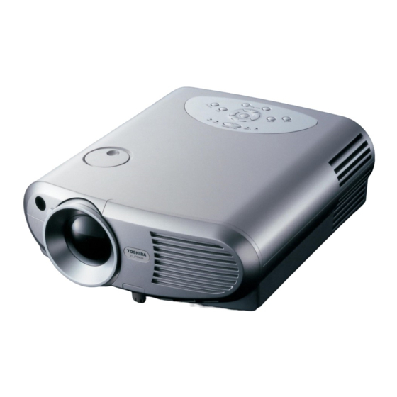
Toshiba TLP-560
Revision A
Advertisement
Table of Contents

Related Manuals for Toshiba TLP-560


Summary of Contents for Toshiba TLP-560
- Page 1 Wire the Panel RS-232 port to a male DB9 as follows: RX to TX to GND to Connect this male DB9 to the Toshiba adapter cable and connect to projector port labeled CONTROL 2. Infrared Emitter: Wire the Panel IR/Serial port to a female 1/8" Mini as follows: IR/SER to...
- Page 2 Panel, see the SmartPanel Configuration and Installation Guide. I. PROJECTOR CONTROL A. Volume and Power Control Volume control on the Toshiba is relative. Absolute volume control for this model is possible with use of SP Controls’ optional Audio Follow Video Pre-Amplifier. B. Input Selection Mapping The following table specifies the factory preset input mapping for this Driver.
- Page 3 Control Wiring Option IR Emitter Control for the Toshiba with this Driver is via RS-232 and IR Emitter. The projector does not have a wired remote port. Power polling is not available for this projector. The following table specifies settings for the Panel’s configurable timers. For more information on the inactivity shutdown feature and the lockout timer see the SmartPanel Configuration and Installation Guide.
- Page 4 II. CONTROL WIRING This section specifies how RS-232 and the Infrared Emitter should be wired to the Toshiba projector. PROJECTOR CONTROL A. RS-232 should be connected to the Toshiba control port RS232 IR/SERIAL labeled RS-232C CONTROL. Connection should be as follows: 1.
- Page 5 Only some of the projector controls work. The Panel controls the Toshiba through RS-232 and IR. If only a subset of the controls is working, verify that both types of control wiring are correctly wired.
Need help?
Do you have a question about the TLP-560 and is the answer not in the manual?
Questions and answers