
Subscribe to Our Youtube Channel
Related Manuals for Coatmaster Atline V4


Summary of Contents for Coatmaster Atline V4
- Page 1 Operation manual Maintenance coatmaster Atline / Inline V4 These operating instructions describe the individual steps of an annual Atline / Inline coatmaster maintenance based on a photo documentation.
-
Page 2: Table Of Contents
Parts to be replaced (supplied by CM AG) ................4 Special tools (supplied by CM AG) ..................4 Miscellaneous tools (Not supplied by CM AG) ..............5 Coatmaster Atline ..........................6 Safety instructions ........................6 Remove the cover........................7 Empty the cooling circuit ......................8 Complete emptying ....................... 10 Excitation unit removal ...................... - Page 3 V4.2 – rev. 1 Reset the lamp status ......................38 Harting flex cable for drag chain ....................40 Material ..........................40 Assembling ..........................41 Document Number r: 020600010 Page 2 von 46 Vojtech Petr / 13.06.2019...
-
Page 4: Introduction
Any extensions or changes to the hardware or software are forbidden. If, after you have studied this manual and have received personal training from an employee of coatmaster AG, you are unable to properly perform the work described, contact coatmaster AG. coatmaster AG... -
Page 5: Material
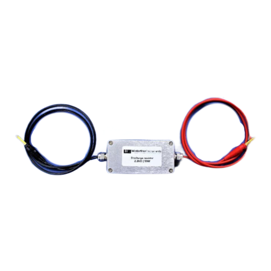
V4.2 – rev. 1 2 Material 2.1 Protection equipment (supplied by CM AG) o discharge resistor 2.2 Parts to be replaced (supplied by CM AG) o 1 x tubes replacement set o 1 x complete light excitation unit o 1 x isolation ring o 8 x plastic screws M6 o 1 x filter mat o 3L of mineral no sparkling water with low... -
Page 6: Miscellaneous Tools (Not Supplied By Cm Ag)
V4.2 – rev. 1 2.4 Miscellaneous tools (Not supplied by CM AG) o Multimeter (1000 VDC/Cat. III) o Cable ties 10mm o Torx screwdrivers set o Cable ties 14mm o Slotted screwdrivers (5 pieces) o Electronic side pliers o Hex keys-Set o Bucket o Torque wrench o Cleaning paper... -
Page 7: Coatmaster Atline
V4.2 – rev. 1 3 Coatmaster Atline 3.1 Safety instructions Before beginning the maintenance on the coatmaster, the following steps must be carried out according to the safety rules of electrical engineering: 3.1.1 Disconnect completely! Switch off the coatmaster and wait until the LED turns off. -
Page 8: Remove The Cover
V4.2 – rev. 1 3.2 Remove the cover 3.2.1 Unscrew the coatmaster Unscrew the 6 x M4 screws on underside of the unit with torx screwdriver. 3.2.2 Remove the cover by sliding Slide gently the cover to the front, take out the rubber cover on the back side and slide the cover back as shown in the picture. -
Page 9: Empty The Cooling Circuit
V4.2 – rev. 1 3.3 Empty the cooling circuit After you have uncovered the coatmaster(see chapter 3.2 Cover remove) and verified the absence of voltage (see chapter 3.1.4 Verify the absence of voltage) is possible to continue with the following steps. - Page 10 3.3.4 Connect the water drain hose and place the other side into the bucket. At this stage, it is possible to connect the water drain hose: turn back the coatmaster on a laying position and position the other side of the hose into the bucket.
-
Page 11: Complete Emptying
This step is carried out until there is no more water in the excitation unit. It can be helpful to move the coatmaster to different angles during the emptying. Once the cooling system is empty, unscrew the water drain hose and screw on the water tank cap. -
Page 12: Excitation Unit Removal
V4.2 – rev. 1 3.5 Excitation unit removal 3.5.1 Disassemble the fasting ring and the front panel Using the special 4-pin washer, the mounting ring is unscrewed, and the front panel can be removed. 3.5.2 Disconnect hoses from the head If the hoses are not marked, take a picture or mark them with a waterproof marker to not forget the right positioning. - Page 13 Unscrew 8 x M6 slotted screws with a screwdriver. Caution: Electrodes of the flash can break off at low mechanical loads. Attention: When the head is completely unscrewed do NOT take it out from the coatmaster! 3.5.7 Unscrew the ignition coil cable Carefully turn the head on its axis and unscrew the ignition coil cable positioned on the bottom of the excitation unit.
- Page 14 V4.2 – rev. 1 3.5.8 Disassemble the IR sensor holder Unscrew the 2 x M3 plastic slotted screws from the head. Loosen 4 x M3 grub screws with a round head hex key until the sensor holder can be removed. It is then possible to change the excitation unit.
-
Page 15: Hoses Replacement
V4.2 – rev. 1 3.6 Hoses replacement 3.6.1 Remove old hoses Take a picture of the hoses positioning or mark them with a permanent marker so that you do not forget the right positioning. 3.6.2 Remove cable ties Cut and remove all 6 cable ties used to secure the hoses using an electronic side cutter. 3.6.3 Remove hoses Remove all 3 transparent hoses by pulling them off from the connection in a controlled manner. -
Page 16: Connect New Hoses
V4.2 – rev. 1 3.7 Connect new hoses 3.7.1 Put hoses on connections Reconnect the cooling system as shown in the following illustration and tie together loosely with 3 cable ties (14 mm). If necessary, shorten the hoses to such an extent that no kinks or to large radii are created. -
Page 17: Install New Excitation Unit
V4.2 – rev. 1 3.8 Install new excitation unit 3.8.1 Mount the IR sensor holder Insert the sensor holder together with the sensor on the new excitation unit. Be sure, that the whole surface of the sensor holder is leaning on the excitation unit. Tighten the 4 x M3 grub screws with the round head hex key. - Page 18 V4.2 – rev. 1 3.8.4 Connect the IR sensor Plug in the two IR sensor connectors. With a torx screwdriver, screw on the grounding wire with spring washer on the left side board. Do not forget to tie all the cables! 3.8.5 Coupling hoses Connect the two hoses in the right position to the excitation unit with the quick-release coupling.
-
Page 19: Cooling Liquid Refill
→ If the pump draws in too much air, there is a possibility that the water will no longer be pumped. In this case, turn off the coatmaster, wait 10 s, and then turn the coatmaster back on. →It is advisable to check the water level every 3 – 4 months and top up with water if necessary. - Page 20 V4.2 – rev. 1 3.9.5 Switch off the coatmaster and unplug the power cable Switch off the coatmaster and wait until the LED turns off. Disconnect all cables from the device and tie them together. Wait at least 2 minutes.
-
Page 21: Replace Filter Mat
V4.2 – rev. 1 3.10 Replace filter mat 3.10.1 Dismantling the fan grille Loosen 2 x M3 screws with a torx screwdriver and remove fan grille 3.10.2 Replace filter mat Take out the old filter mat and insert the new one. 3.10.3 Mount the fan grille Mount the fan grille and secure with 2 x M3 screws Document Number r: 020600010... -
Page 22: Close The Device
3.11.2 Visual inspection Before the coatmaster is screwed on again, make sure that there are no loose small parts or tools in the device, otherwise there is a possibility of damaging the coatmaster. 3.11.3 Connect the flash generator Reconnect the power supply cable of the flash generator, on the power distribution board 3.11.4 Mount the cover and connect the grounding... - Page 23 V4.2 – rev. 1 3.11.6 Mount the reflector By turning by hand clockwise, the reflector on the front of the device can be screwed on. Make sure that the reflector is not tightened until the correct thread has been cut, otherwise the thread will be damaged (the reflector can be turned in without great effort).
-
Page 24: Coatmaster Inline
4.1.1 Disconnect completely! Switch off the coatmaster and wait until the front LED turns off. 4.1.2 Secure against reconnection! Disconnect all cables from the device and tie them together. -
Page 25: Empty The Cooling Circuit
V4.2 – rev. 1 4.2 Empty the cooling circuit To empty the water from the cooling system open the circuit between the head and the cooling unit. Disconnect the water tubes from the connectors Nr. 1 on the head. Connect the ventilation tube to the connector of the head and the second emptying tube to the end of the yellow water tube as showed in the pictures. -
Page 26: Head Cover Removal
V4.2 – rev. 1 4.3 Head cover removal 4.3.1 Disconnect the water tubes from the head and the cooling unit By pulling the water tube from the device, it is possible to disconnect the tubes. 4.3.2 Unscrew the head cover Unscrew the 4 x M4 screws on the bottom side of the head with a torx screwdriver. -
Page 27: Excitation Unit Removal
V4.2 – rev. 1 4.3.4 Disconnect the grounding wire Disconnect the grounding wire from the bottom of the cover 4.3.5 Completely remove the cover from the back side At this stage, it is possible to completely remove the cover by sliding it to the back side. 4.3.6 Interior cleaning If necessary, remove dust and dirt particles with compressed air (not oiled). - Page 28 V4.2 – rev. 1 4.4.3 Disconnect hoses from the head If the hoses are not marked, take a picture or mark them with a waterproof marker so that you do not forget the right positioning. Disconnect the two hoses from the excitation unit using a quick-release coupling. 4.4.4 Cut the IR sensor cable ties 4.4.5 Unscrew the grounding wire With a torx screwdriver, unscrew the grounding wire from the left side board.
- Page 29 Unscrew the 8 x M6 slotted screws with a screwdriver. Caution: Electrodes of the flash can break off at low mechanical loads. Attention: When the head is completely unscrewed do NOT take it out from the coatmaster! 4.4.8 Unscrew the ignition coil cable Carefully turn the head on its axis and unscrew the ignition coil cable positioned on the bottom of the excitation unit.
-
Page 30: Head Hoses Replacement
V4.2 – rev. 1 4.4.9 Disassemble the IR sensor holder Unscrew the 2 x M3 plastic slotted screws from the head. Loosen 4 x M3 grub screws with a round head hex key until the sensor holder can be removed. At this stage, it is possible to change the excitation unit. - Page 31 V4.2 – rev. 1 4.5.2 Remove hoses Remove both hoses by pulling them off from the connection in a controlled manner. TTENTION ANGER OF INJURY DUE TO SHARP EDGES IN THE DEVICE 4.5.3 Connect new hoses Cut 5 new hoses at the same length as the old. If necessary, shorten the hoses to such an extent that no kinks or to large radii are created.
-
Page 32: Install New Excitation Unit
V4.2 – rev. 1 4.6 Install new excitation unit 4.6.1 Mount the IR sensor holder Insert the sensor holder together with the sensor on the new excitation unit. Be sure, that the whole surface of the sensor holder is leaning on the excitation unit. Tighten the 4 x M3 grub screws with the round head hex key. - Page 33 V4.2 – rev. 1 4.6.4 Connect the IR sensor Plug in the two IR sensor connectors. With a torx screwdriver, screw on the grounding wire with spring washer on the left side board. Do not forget to tie all cables! 4.6.5 Coupling hoses Connect the two hoses at the right position to the excitation unit with the quick-release coupling.
-
Page 34: Close The Head
4.7.2 Visual inspection Before the coatmaster is screwed on again, make sure that there are no loose small parts or tools in the device, otherwise there is a possibility of damaging the coatmaster. 4.7.3 Mount the cover and connect the grounding wire The cover slides from the back side on the coatmaster. -
Page 35: Open The Cooling Unit
V4.2 – rev. 1 4.7.5 Mount the reflector By turning by hand clockwise, the reflector on the front of the device can be screwed on. Make sure that the reflector is not tightened until the correct thread has been cut, otherwise the thread will be damaged (the reflector can be turned in without great effort). - Page 36 V4.2 – rev. 1 4.9.1 Remove cable ties Cut and remove all cable ties used to secure the hoses using an electronic side cutter. 4.9.2 Remove hoses Remove all 5 transparent hoses by pulling them off from the connection in a controlled manner. TTENTION ANGER OF INJURY DUE TO SHARP EDGES IN THE DEVICE 4.9.3 Connect new hoses...
-
Page 37: Close Cooling Unit
4.10.1 Visual inspection Before the cooling unit is screwed on again, make sure that there are no loose small parts or tools in the device, otherwise there is a possibility of damaging the coatmaster. 4.10.2 Screw in the cooling unit cover Tighten the 7 x M3 screws on the top and on the backside of the cooling unit with a torx screwdriver. -
Page 38: Testing And Updates
When the tank is full, a bit of water will leak from the ventilation slot. Start the coatmaster with the front button. As a result, the water pump will push water into the cooling circuit and the water tank begins to empty. -
Page 39: Reset The Lamp Status
5.2 Reset the lamp status Check the actual light source status and reset it, if needed. Click on “help” tab and open the “about this coatmaster” window. In the second line, there is the actual light source status in percentage. - Page 40 The offset must be inserted in the fourth position from the left side at flash power offset count as showed in the following picture. Apply the changes and restart the coatmaster. When it started up, control that the light source status is reset.
-
Page 41: Harting Flex Cable For Drag Chain
V4.2 – rev. 1 6 Harting flex cable for drag chain 6.1 Material 6.1.1 Cables • 2x Highly flexible PUR braided black cable 10mm , suitable for drag chains • 1x Highly flexible PUR braided green & yellow cable 10mm , suitable for drag chains •... -
Page 42: Assembling
V4.2 – rev. 1 6.2 Assembling Pull the cable over the cable gland and the plug housing. Mount the Harting modules as follow Document Number r: 020600010 Page 41 von 46 Vojtech Petr / 13.06.2019... - Page 43 V4.2 – rev. 1 Signal module (12pin); strip 9mm; the numbers on the wires correspond with the numbers on the module. The grounding is connected at position no. 12 of the module. To connect the wires, clamp the module in the vice. Do not twist the copper wires. Power module;...
- Page 44 V4.2 – rev. 1 RJ-45 module; strip 22mm; crimp a common ethernet connector to the cable. Both sides have to be wired in the same way. Mount the modules to the frame in the right order. Document Number r: 020600010 Page 43 von 46 Vojtech Petr / 13.06.2019...
- Page 45 V4.2 – rev. 1 Connect the grounding cable to the frame. Mount the plug housing on the frame by screwing the contact elements on the front side. Document Number r: 020600010 Page 44 von 46 Vojtech Petr / 13.06.2019...
- Page 46 V4.2 – rev. 1 Screw the cable gland to the plug housing by hand. Push the protective tube into the cable gland until it is fully engaged. Document Number r: 020600010 Page 45 von 46 Vojtech Petr / 13.06.2019...
- Page 47 V4.2 – rev. 1 coatmaster AG Flugplatzstrasse 5 CH-8404 Winterthur T +41 52 511 87 77 F +41 52 511 87 49 info@coatmaster.com www.coatmaster.com Document Number r: 020600010 Page 46 von 46 Vojtech Petr / 13.06.2019...
Need help?
Do you have a question about the Atline V4 and is the answer not in the manual?
Questions and answers