Table of Contents
Advertisement
Quick Links
Advertisement
Table of Contents

Related Manuals for Coatmaster 3D


Summary of Contents for Coatmaster 3D
- Page 1 3D user manual...
- Page 2 All rights reserved. No part of this publication may be reproduced, distributed, or transmitted in any form or by any means, including photocopying, recording, or other electronic or mechanical methods, without the prior written permission of the publisher, except certain noncommercial uses permitted by copyright law. © 2020 coatmaster AG...
-
Page 3: Table Of Contents
Installing coatmaster Desktop Software ............... 20 4.4.3 Define administrator settings within the Operating System......... 21 4.4.4 Dark mode selection ...................... 22 Measuring coating thickness with coatmaster ............23 5.1. Measuring principle ..................... 23 5.2. coatmaster application for rough surfaces ..............24 5.3. - Page 4 Setup application ......................32 5.6. Measuring with coatmaster Operating System ............. 35 5.6.1. Adjusting the position of the coatmaster 3D head ............36 5.6.2. Adjusting the position of the coatmaster 3D lamps ............37 5.6.3. Management of the applications .................. 40 5.6.4.
- Page 5 3D user manual 10.1. Transport inspection ....................60 10.2. Packaging ........................ 60 10.3. Storage ........................60 Appendix A: tests with flame detector ..............62 11.1. STS flame detector ....................62 11.2. Total Walther UV-03 flame detector ................. 63 5/63...
-
Page 6: General
General 1.1 Information This manual describes the coatmaster 3D and provides all information required for its safe operation and to maintain it in good working order. Read this manual carefully before installing and running your system and note the safety precautions in chapter 2 in particular. -
Page 7: Copyright
Software updates can affect or damage the coatmaster and are therefore prohibited. coatmaster AG assumes no liability for data loss on the embedded PC. It is suggested to regularly backup the data on the embedded PC (application and measurement data). - Page 8 1 CM control unit (19“-rack insert, 3 height units) • 6 lamps mountend on aluminum support • 1 USB stick with the coatmaster 3D User Interface • 1 set of cables (up to 10 Ethernet cables max 25m each, 4 90-264V C13/C14, 1 90-264V C20, •...
-
Page 9: Safety
Opening the coatmaster’s housing. Exception: Cleaning or changing the filter pad (see chap- ter 7). This is also valid when the coatmaster is not connected to the mains. When the coat- masters is opened, the warranty is void and the manufacturer disclaims all liability. -
Page 10: Use In The Presence Of Flame Dectectors
The alarm of the flame detector from the brand STS (models FL-8.64 and FL.9) is not trig- gered for UV+IR setting in any combination of coatmaster type and flame detector type. The alarm is triggered only for IR setting. The certification page by the company STS Brand- schutzsysteme GmbH (Germany) can be found in chapter 11.1 on page 62. -
Page 11: Used Symbols
3D user manual DANGER Supplementary text, describing the hazard/risk (e.g. explosion). Result of the hazard if not avoided (e.g. death). 1. List of measures to avoid the herein described hazard or harzardous situation. 2.6.2 Used symbols The below reference list incorporates all safety information symbols used in this manual or on the device and their meaning. -
Page 12: General Hazards
CAUTION Integrated light source. The coatmaster® contains a flash lamp which falls under the risk group 3 according to the photobiological safety of IEC62471:2015. The coatmaster® does not emit harmful UV radiation. Hazardous optical radiation may possibly be emitted from this product in case of di- rect and narrow eye contact. -
Page 13: Integrated Safety Elements
3D user manual Ozone Formation If the room is not enough ventilated, the ozone can lead to respiratory disease. ◊ Closed rooms must be ventilated frequently to prevent excessive ozone formation which can result from the use of strong flash units. -
Page 14: Coatmaster Hardware Interfaces
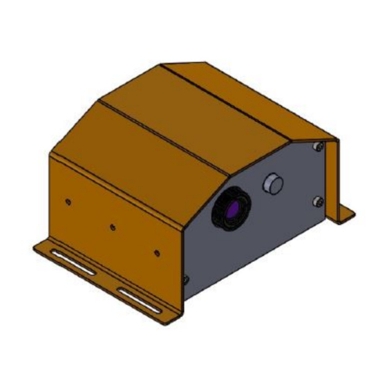
3D user manual 3 coatmaster Hardware Interfaces 3.1 coatmaster 3D Figure 1. 3D CAD illustration of the coatmaster 3D optical head Figure 2. Frontal (upper) and top (lower) views of the coatmaster 3D optical head 14/63... - Page 15 3D user manual Figure 3 coatmaster 3D generator unit rack 15/63...
- Page 16 3D user manual Figure 4 coatmaster 3D control unit for different versions (2, 4, 6 and 8 lamps) 16/63...
-
Page 17: System Installation
The installation of the device must be done only by an integrator (partner of the customer or directly from coatmaster AG). The device may only be used by persons who on account of training or profes- sional experience have an overview of the dangers which may arise when operating the device. -
Page 18: Software Requirements
3D Operating System: Starting measurements, creating applications, exporting measure- ment data, display measurement values and statistics. The creation of applications and the export of measurement data can only be done with the coatmaster 3D Operating System. The software must be installed on a Windows-PC. -
Page 19: Interface To Connect With Control Computer
3D Operationg System. This is described in chapter.5.5 Interface to connect with control computer To be able to operate the coatmaster 3D, the computer must be connected with an Ethernet cable to the coatmaster 3D. Network and administrator settings Make sure that the coatmaster is correctly installed as described in chapter 4.1 Hardware installation... -
Page 20: Installing Coatmaster Desktop Software
6. In the dialog window select the coatmaster to connect to (see Figure 8). 7. In case the coatmaster does not appear in the list select the add new device button and enter the IP address of the coatmaster 3D (here: 192.168.10.155) 8. -
Page 21: Define Administrator Settings Within The Operating System
In the window settings under the tab options is possible, by the software administrator, to disable the editing and deleting of the application for users. Figure 8. Administrator settings in coatmaster software To change the setting, click on the empty square of lock the user interdace. A Login dialog opens. Ad- ministrator password: admino041. -
Page 22: Dark Mode Selection
4.4.4 Dark mode selection If on the working station, where the coatmaster 3D computer is positioned, there is too much light, is possible to change the color of the operating system as follow. Clicking on Options -> Settings in the main window of the coatmaster 3D GUI a window with multiple options will appear. -
Page 23: Measuring Coating Thickness With Coatmaster
3D user manual 5 Measuring coating thickness with coatmaster The technology used for all coatmaster AG’s products is following the requirements of the norm DIN EN ISO 2808. The coatmaster technology belongs to the Photothermal method as described by the norm. -
Page 24: Coatmaster Application For Rough Surfaces
3.00 3.50 4.00 Measurement distance [m] Figure 11 : coatmaster 3D measuring area as a function of the measurement distance for different optics of the front cam- era. The working distance can be selected according to the following rules: •... -
Page 25: Best Practices
Table 1 Measurement area for different camera optics 5.3. Best practices We give in this section some hints on how to optimally use your coatmaster, for in-line measure- ments. 5.3.1. Measuring on moving parts (optional) It is possible to measure coating thicknesses on moving parts for in-line coating application. -
Page 26: Setting The Measuring Time
At any time is possible to check the status of the flash generators. If a lamp does not flash and it’s a generator problem, it will be showed in this window. To open it click on File -> Flash unit and the fol- lowing window will appear. If any of the generators shows an error, contact coatmaster AG. 26/63... -
Page 27: Setting The Energy Level And Lamp Lifetime
Figure 14 Flash generator error window 5.3.4. Setting the energy level and lamp lifetime The coatmaster can measure in 7 steps with energy settings from 750J to 3000J. The quality of the measured temperature curve depends on the energy setting, the measuring distance, the measuring angle and the color of the coating. -
Page 28: Nuc
The coatmaster can be used to measure coating thickness before curing without touching (and thus destroying) the coating. This allows to use the coatmaster for process control and to establish pro- cess statistics. For this purpose, the coatmaster can be configured to predict cured coating thickness from measurements before curing. - Page 29 50kV and a conveying air of xx l/min. After powder coating, the layer thickness distribution is measured with a coatmaster 3D before baking (see Figure 39). The measured image section is 25 mm x 25 mm, with a spatial resolution of 100µm.
-
Page 30: Measuring Wet Coatings Before Curing/Drying
3D user manual Figure 17 Coating thickness distrubution on profiles with different radii of curvature recorded with a coatmaster 3D at- line 5.4.2. Measuring wet coatings before curing/drying The wet coating thickness is usually measured to determine the thickness of the coating after curing. -
Page 31: Making New Coatmaster Applications
(e.g. microscopic cross-section analysis). Enter the coating thickness in the “wet” coat- master applications. 5. If possible and required, make a second new application on the coatmaster, adding reference measurement on the cured reference parts at the same positions. If the parts have been cut for microscopic analysis, make the reference measurements close to the original position. -
Page 32: Setup Application
(e.g. on metal or plastic or on aluminium or steel) for each subtrate material a new coatmas- ter application should be created. The reference samples should be kept, if possible, to check the long-term stability of the coatmaster. To make a new application, produce the reference samples and keep them at hand for the calibration process. - Page 33 3D user manual Figure 18 defining a reference measurement 5. Have at least 2 reference points to make a proper calibration whole list appears in the left bottom part of the window (see Figure 18). In this list, you can remove reference points by pressing the Remove button in the reference list.
- Page 34 3D user manual Figure 20 Removing calibration point 2 6. Select the Data View tab to display the temperature decay curves of the reference points (see Figure 20). 7. Adjust the measurement duration with the sliding button as described in chapter 5.3.2, so that it corresponds a value which corresponds to the end of the decay curves (in this case around 0.5 s).
-
Page 35: Measuring With Coatmaster Operating System
After connecting with the coatmaster, start the coatmaster 3D Operating System. The main window opens (see Figure 17). Figure 22 The main window of the coatmaster 3D Operating System is divided into four areas: 1. Menu, 2. Applications, 3. Measure and 4. Previous measurements... -
Page 36: Adjusting The Position Of The Coatmaster 3D Head
On the coatmaster 3D User Interface, select the Ir live View tab (see Figure 22) If your coatmaster 3D is well set up, you should see a live image of the IR camera Adjust the camera focus by tourning the objective ring to get a sharp image on the screen. -
Page 37: Adjusting The Position Of The Coatmaster 3D Lamps
3D user manual Figure 24 Camera rotation option 5.6.2. Adjusting the position of the coatmaster 3D lamps 1. Preposition the lamps so that they illuminate symmetrically the samples to be measured 2. Make sure that the lamps are not covering in the field of view the camera (tab IR live View) 3. - Page 38 3D user manual 6. Adjust the threshold sliding button (see Figure 26) and check that all parts of the object you want to measure sees an increase of its temperature of 0.4°C. Set the threshold value, so that the temperature increase of background scene does not interfere too much with your object (see Figure 27).
- Page 39 3D user manual 8. Reiterate the operation 1 to 7 until you get a satisfactory result. 39/63...
-
Page 40: Management Of The Applications
3D user manual 5.6.3. Management of the applications The left part of the User Interface is dedicated to the management of calibrations (see Figure 18). Make a new application by pressing the add App button as described in chapter 5.5. -
Page 41: Manual Measurement
Press the Measure button to do a thickness measurement. Figure 30 Measurement 5.6.5. Visualising results with the coatmaster 3D The measurement you did after pressing Measure button will be displayed automatically in the result View tab (see Figure 30). The thickness mapping is displayed in false color and by pointing the mouse on any measurement point, you can display the measured thickness value (here 79 microns). - Page 42 3D user manual Figure 31 Measurement result You can zoom-in or out the results by positioning the mouse on the map and scrolling your mouse. You can displace the map by maintening the left-click on the mouse and displacing the map.
- Page 43 3D user manual You have the possibilities to define freely Regions of Interest (ROI) to display geometrical statistical values (minimum, maximum, average and standard deviation of the measured values). a. Select the ROI button (see Figure 36) and click on the ADD ROI button.
-
Page 44: System Information
3D user manual Selecting the 3D view option as showed in Figure 35 you can change the result view into 3D form. Po- sitioning the mose on a certain point, the actual thickness value will be showed. To zoom-in and -out there is a slider on the right part of the window called scale factor. -
Page 45: Back-Up And Transfer Of Coatmaster 3D Applications
Back-up and Transfer of coatmaster 3D applications Application data is stored in the coatmaster’s embedded PC. If this PC crashes or is destroyed the work to create the applications is lost. It is therefore strongly recommended to save applications by exporting this data from the coatmaster to an external storage. -
Page 46: Import Applications
3D user manual 5.7.2. Import applications To import previously exported applications, select File > Import Application (see Figure 40). Figure 40. Window for importing an application in the stand-alone software In the dialog window, select the application from the folder where it was previously saved and click on import. -
Page 47: Export Measurement Data
Clicking on Export measurements a window will appear where you have to choose the folder, where the measurements will be saved. When you click Ok the measures will be exported. The measurements are exported in a CM3DBIN file format, which can be read only by a coatmaster 3D software. -
Page 48: Exporting Data Automatically
3D user manual 5.8.2. Exporting data automatically Opening Options -> Settings you can enter into the settings for the automatic measurements export (see Figure 41). Figure 42 Automatic export settings Select save measuremetns locally and select the path (folder, where the measurements will be saved). -
Page 49: Remote Control
The coatmaster is operated by commands that are sent from the device to the coatmaster. The result of the command is sent back from the coatmaster to the device. The coatmaster acts as a server for remote control operation. The device acts as a client. - Page 50 3D user manual „CR/LF“: ends the command (line break (Hex 0D 0A, escape sequence \r\n) depending on the PLC in use) 50/63...
-
Page 51: Measure Command
MESSAGE=<VAL>: Description of the problem in case of an error or warning message 6.1.2. MEASURE command Use the MEASURE command to trigger a coatmaster measurement. You have to select a coatmaster application for the measurement. This is specified by an ID which is the only argument for the MEAS- URE command. -
Page 52: Getconfiguration Command
3D user manual • Example command o MEASURE?CONFIG_ID=1&ORDER_NR=Batch1\r\n • Example answer RES_MEASURE?STATUS=OK&CONFIG_ID=1&MEASURE_ID=2548& TIMESTAMP=125478954 & [NAME,VALID,MIN,MAX,AVG,DEV]=[RIO34,true,1,23,12,1.2] \r\n 6.1.3. GETCONFIGURATION command Use the GETCONFIGURATION command to retrieve the name and the Id of an application stored on the coatmaster. • GETCONFIGURATION •... -
Page 53: Getconfigids Command
Example command • GETCONFIGIDS\r\n • Example answer o RES_GETCONFIGIDS?STATUS=OK&ID=1&ID=5&ID=7\r\n 6.1.6. GETCOATMASTERSTATUS Use this command to get general information on the coatmaster. This command has no arguments. • GETCOATMASTERSTATUS • Description Returns the current status of the coatmaster READY=1 -> ready to flash (min wait time reached & flash generator ready & safety... -
Page 54: Get_Flash_Energy Command
3D user manual • Example command GETCOATMASTERSTATUS \r\n Example answer • o RES_GETCOATMASTERSTATUS?STATUS=OK&READY=1&GENERATOR_READY=1 &SAFETY_SWITCH=1&FUS_AVAILABLE=1f&FUS_READY=1f\r\n 6.1.7. GET_FLASH_ENERGY command Use the GET_FLASH_ENERGY command to request the current energy set of the generators This com- mand has no arguments. • GET_FLASH_ENERGY •... -
Page 55: Siemens S7
3D user manual o SET_FLASH_ENERGY\r\n 6.2. Siemens S7 Important note for users of a Siemens SIMATIC S7 PLC: The Siemens S7 PLC is available in two different product types, which react differently with an Ether- net connection – Type PN/DP and Type DP. -
Page 56: Maintenance / Service
Prior to any maintenance and service, switch off the device and unplug the mains cable. Mainte- nance work may be conducted by authorized personnel only! Do not open the housing of the coatmaster, even when the coatmaster is not connected to the mains. Opening the coatmaster will void any liability and annuls the guarantee. -
Page 57: Climatized Electrical Cabinet Air Filter
3D user manual 7.5. Climatized electrical cabinet air filter On the air conditioning system of the electrical cabinet (if present) there is a filter pad which need to be inspected regularly. When is contaminated, it needs cleaning. For very strong contamination an exchange is necessary. -
Page 58: Troubleshooting
3D user manual 8. Troubleshooting If a software error occurs, restart the device. If the error persists, contact your administrator and pass the error code. In case of hardware defect or malfunction proceed as follows: Disconnect the device from the control unit immediately. -
Page 59: Technical Data
3D user manual 9. Technical data 9.1. Data sheet coatmaster 3D coatmaster 3D Energy 750 J – 3000 J Measurement distance 10 cm – 120 cm Measurement area fully scalable Measurement range: 1-2000 µm Measurement duration 0.5s 2,9 s at 750 J... -
Page 60: Transport, Packaging, Storage
3D user manual 10. Transport, packaging, storage 10.1. Transport inspection delivery must checked completeness possible transit damage immediately at receipt. In case of externally visible damage, proceed as follows: Do not accept the delivery or only under reserve. •... - Page 61 3D user manual Appendices 61/63...
-
Page 62: Appendix A: Tests With Flame Detector
3D user manual 11. Appendix A: tests with flame detector 11.1. STS flame detector ___________________________________________________ 62/63... -
Page 63: Total Walther Uv-03 Flame Detector
3D user manual 11.2. Total Walther UV-03 flame detector 63/63...
Need help?
Do you have a question about the 3D and is the answer not in the manual?
Questions and answers