Table of Contents
Advertisement
Quick Links
Advertisement
Table of Contents

Related Manuals for RAM TRX 2023


Summary of Contents for RAM TRX 2023
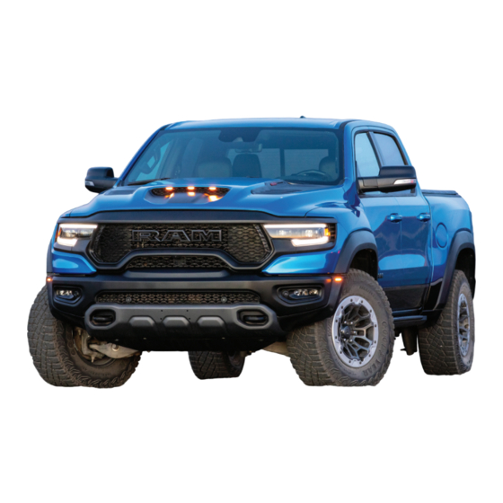
- Page 1 2023 RAM TRX PERFORMANCE FEATURES GUIDE...
-
Page 3: Table Of Contents
TABLE OF CONTENTS INTRODUCTION ..........................4 GETTING TO KNOW YOUR VEHICLE ................... 7 GETTING TO KNOW YOUR INSTRUMENT PANEL ............9 STARTING AND OPERATING ....................19 MULTIMEDIA ..........................40 SAFETY ............................66 IN CASE OF EMERGENCY ...................... 69 SERVICING AND MAINTENANCE ..................79 TECHNICAL SPECIFICATIONS .................... - Page 4 INTRODUCTION GETTING TO KNOW YOUR STARTING AND OPERATING INSTRUMENT PANEL ENGINE BREAK-IN RECOMMENDATIONS SYMBOLS KEY............5 6.2L SUPERCHARGED ENGINE......19 SLIDE-IN CAMPERS ..........5 INSTRUMENT CLUSTER ........... 9 AUTOMATIC TRANSMISSION ....... 19 Camper Applications .......... 5 Premium Instrument Cluster Ignition Park Interlock........20 VEHICLE MODIFICATIONS/ALTERATIONS.....5 Descriptions —...
- Page 5 MULTIMEDIA SAFETY SERVICING AND MAINTENANCE PERFORMANCE PAGES ........40 SAFETY FEATURES..........66 SCHEDULED SERVICING ........79 Timers ...............40 Electronic Stability Control (ESC) ....66 Maintenance Plan..........81 Gauges ..............42 ESC Operating Modes ........67 ENGINE COMPARTMENT ........85 Dynamometer (Dyno)/Engine......43 SAFETY TIPS ............68 6.2L Supercharged Engine G-Force..............45 Fluid Leaks ............68 (Beauty Cover Removed) .........85...
-
Page 6: Introduction
Dear Customer, This Supplement has been prepared with the assistance of service and engineering specialists to acquaint you with the operation and maintenance of your Ram. Within this information, you will find a description of the services that FCA US LLC offers to its customers. Please take the time to read all of this publication carefully before driving your vehicle for the first time. -
Page 7: Symbols Key
SYMBOLS KEY SLIDE-IN CAMPERS These statements apply to operating procedures AMPER PPLICATIONS WARNING! that could result in a collision, bodily injury and/or death. This vehicle is not recommended for slide-in camper applications. These statements apply to procedures that could VEHICLE MODIFICATIONS/ALTERATIONS result in damage to your vehicle. -
Page 8: Symbol Glossary
SYMBOL GLOSSARY Drive Mode Indicator Lights Some car components have colored labels with symbols indicating Baja Mode Indicator Light precautions to be observed when using this component. It is important to Ú page 18 follow all warnings when operating your vehicle. See below for the definition of each symbol Ú... -
Page 9: Getting To Know Your Vehicle
GETTING TO KNOW YOUR VEHICLE EXTERIOR LIGHTS INTERIOR STORAGE AND EQUIPMENT EADLIGHT WITCH TORAGE Center Console Storage Area The headlight switch controls the clearance lamps and the front and rear identification lamps. The center console storage area consists of a The clearance lamps and the front and rear cubby bin (located in front of the gear selector) and identification lamps will turn on when the switch... -
Page 10: Power Inverter - If Equipped
GETTING TO KNOW YOUR VEHICLE — I To access the cupholders, push on the cover to The outlet remains off when no device is plugged OWER NVERTER QUIPPED open it. in. To turn on the power outlet, simply plug in a A 115 Volt (400 Watt maximum) inverter may be device. -
Page 11: Getting To Know Your Instrument Panel
GETTING TO KNOW YOUR INSTRUMENT PANEL INSTRUMENT CLUSTER... -
Page 12: Descriptions - Gasoline
GETTING TO KNOW YOUR INSTRUMENT PANEL 5. Fuel Gauge REMIUM NSTRUMENT LUSTER WARNING! — G The pointer shows the level of fuel in the ESCRIPTIONS ASOLINE A hot engine cooling system is dangerous. You or fuel tank when the ignition is in the ON/RUN others could be badly burned by steam or boiling 1. -
Page 13: Instrument Cluster Display Controls
GETTING TO KNOW YOUR INSTRUMENT PANEL NSTRUMENT LUSTER ISPLAY ISPLAY TEMS ONTROLS Push and release the up or down arrow button until the desired selectable menu icon is The instrument cluster display features a driver highlighted in the instrument cluster display. interactive display that is located in the instrument cluster. - Page 14 GETTING TO KNOW YOUR INSTRUMENT PANEL Driver Assist — If Equipped Vehicle Info Push the SET + or the SET- button (located on the steering wheel) and the following will display in the The Driver Assist menu displays the status of the Push and release the up or down arrow...
- Page 15 GETTING TO KNOW YOUR INSTRUMENT PANEL Oil Summary Battery Tire Pressure Drag Timers WARNING! Voltage Monitor 0-60 feet 0-330 feet Measurement of vehicle statistics with the System Tempera- Storage (0-20 meters)/ (0-100 meters) Timer Performance Features is intended for ture Mode Reaction Timer...
- Page 16 GETTING TO KNOW YOUR INSTRUMENT PANEL Braking Distance Drivetrain Wheel Articulation Distance Front Wheel Angle: displays the graphical Displays the range of vertical height. and numerical value of calculated average From Speed When height is normal, axle half shaft is ...
- Page 17 GETTING TO KNOW YOUR INSTRUMENT PANEL Speed Warning Settings Favorite Menus Screen Setup Driver Selectable Items Push and release the up or down arrow Performance Speedometer Vehicle Info button until the Speed Warning Menu icon/title is Show/Hide Push and release the up or down arrow displayed in the instrument cluster display.
-
Page 18: Head Up Display (Hud) - If Equipped
GETTING TO KNOW YOUR INSTRUMENT PANEL Fuel Gauge Lower Left and Right – If Equipped Hide Range None Compass Outside Temp Show Range Range To Time Average Econ Defaults (Restores All Settings To Default Settings) Empty Cancel Current Econ Trip A Distance Trip B Distance Restore... -
Page 19: Trx Drive Mode
GETTING TO KNOW YOUR INSTRUMENT PANEL TRX D When “Standard” mode is selected, the Custom 4: Speed, Speed Limit, Navigation, RIVE HUD image is split into thirds with the speed Driver Assist (ACC/Cruise, LaneSense, limit indicator shown to the left, vehicle Highway Assist/Highway Assist+), Gear speed in the center, and turn-by-turn navi- Sport View... -
Page 20: Warning Lights And Messages
GETTING TO KNOW YOUR INSTRUMENT PANEL WARNING LIGHTS AND MESSAGES Mud/Sand Mode Indicator Light RIVE NDICATOR IGHTS This light will turn on when Mud/Sand Sport Mode Indicator Light The warning/indicator lights will illuminate in the mode is active Ú page 53. instrument panel together with a dedicated This light will turn on when Sport mode is message and/or acoustic signal when applicable. -
Page 21: Starting And Operating
STARTING AND OPERATING ENGINE BREAK-IN RECOMMENDATIONS NOTE: 100 to 300 miles (161 to 483 km): Check engine oil with every refueling and add if Press the accelerator pedal slowly and not more 6.2L SUPERCHARGED ENGINE necessary. Oil and fuel consumption may be higher than halfway to avoid rapid acceleration in lower through the first oil change interval. -
Page 22: Ignition Park Interlock
STARTING AND OPERATING GNITION NTERLOCK WARNING! WARNING! This vehicle is equipped with an Ignition Park The transmission may not engage PARK if the When exiting the vehicle, always make sure Interlock which requires the transmission to be in vehicle is moving. -
Page 23: 8-Speed Automatic Transmission
STARTING AND OPERATING 8–S The electronically controlled transmission adapts NOTE: PEED UTOMATIC RANSMISSION its shift schedule based on driver inputs, along If the gear selector cannot be moved to the PARK, The transmission gear range is displayed both with environmental and road conditions. REVERSE, or NEUTRAL position (when pushed beside the gear selector and in the instrument forward), it is probably in the AutoStick (+/-) - Page 24 STARTING AND OPERATING When exiting the vehicle, always: Look at the transmission gear position display CAUTION! and verify that it indicates the PARK position (P), Apply the parking brake and is not blinking. Towing the vehicle, coasting, or driving for any Shift the transmission into PARK ...
- Page 25 STARTING AND OPERATING During extremely cold temperatures The Malfunction Indicator Light (MIL) may be An authorized dealer has diagnostic equipment to (-22°F [-30°C] or below), transmission operation illuminated. A message in the instrument cluster assess the condition of your transmission. If the may be modified depending on engine and will inform the driver of the more serious transmission cannot be reset, an authorized...
-
Page 26: Four-Wheel Drive Operation
STARTING AND OPERATING Operation You can start out, from a stop, in FIRST or WARNING! SECOND gear (or THIRD gear, in 4WD LOW In AutoStick mode, you can use the gear selector range, SNOW mode). Tapping (+) (at a stop) will Do not downshift for additional engine braking (in the SPORT position), or the paddle shifters, to allow starting in SECOND gear. - Page 27 STARTING AND OPERATING This electronically shifted transfer case provides 4WD HIGH N (Neutral) four positions: Four-Wheel Drive High Range — This range WARNING! provides torque to the front driveshaft Four-Wheel Drive Automatic High Range (4WD AUTO) (engages four-wheel drive) which allows front and You or others could be injured or killed if you ...
- Page 28 STARTING AND OPERATING NOTE: This electronically shifted transfer case is designed Transfer Case Position Indicator Lights to be driven in the four-wheel drive auto position Before retrying a selection, make certain that all The Transfer Case Position Indicator Lights (4WD (4WD AUTO) for normal street and highway the necessary requirements for selecting a new HIGH and 4WD LOW) are located in the instrument...
-
Page 29: Selec-Speed Control (Ssc)
STARTING AND OPERATING (SSC) Proper operation of four-wheel drive vehicles 2. Enabled (feature is enabled and ready but ELEC PEED ONTROL depends on tires of equal size, type and activation conditions are not met, or driver is circumference on each wheel. Any difference in actively overriding with brake or throttle tire size can cause damage to the drivetrain. - Page 30 STARTING AND OPERATING NOTE: The set speed for SSC is selectable by the driver, Disabling SSC and can be adjusted by using the paddle shifters or During SSC, the (+/-) gear selector input is used SSC will deactivate and be disabled if any of the ...
-
Page 31: Trx Modes
STARTING AND OPERATING The cluster icon and switch lamp will flash for TOW – This mode minimizes transmission gear several seconds then extinguish when SSC changes and adapts the suspension for towing disables due to excess speed. or hauling heavy loads. Drive torque is more evenly split between the front and rear wheels The cluster icon and switch lamp will flash then ... - Page 32 STARTING AND OPERATING Adaptive Damping System MUD/SAND – This mode maximizes traction Use of this feature in low traction with equal torque split front and rear. Traction (cold, wet, gravel, etc.) conditions may results in This vehicle is equipped with an electronically control intervention is reduced to allow for peak excess wheel slip outside this system’s control controlled damping system.
- Page 33 STARTING AND OPERATING Launch Control is intended to be used on dry, 3. Push the LAUNCH button on the TRX control Launch control will be active until the vehicle paved road surfaces only. switch or press the Activate Launch Control reaches 62 mph (100 km/h), at which point the button on the touchscreen;...
-
Page 34: Axle Locker System
STARTING AND OPERATING AXLE LOCKER SYSTEM Operating the locker in 4WD AUTO and 4WD HIGH, CAUTION! the locker can be engaged up to 20 mph (32 km/h). This vehicle is equipped with an electronically It will remain engaged throughout the entire 4WD Do not lock the rear axle on hard surfaced ... -
Page 35: Driving Tips
STARTING AND OPERATING DRIVING TIPS RIVING CAUTION! The Basics Of Off-Road Driving Never park your vehicle over dry grass or other RIVING combustible materials. The heat from your You will encounter many types of terrain driving Off-road trucks have higher ground clearance and vehicle exhaust system could cause a fire. - Page 36 STARTING AND OPERATING Simultaneous Brake And Throttle SAND CAUTION! Operation Select MUD/SAND from the TRX modes. Soft sand On icy or slippery roads, do not downshift at high is very difficult to travel through with full tire Many off-road driving conditions require the engine RPM or vehicle speeds, because engine pressure.
- Page 37 STARTING AND OPERATING Crossing Obstacles USING A SPOTTER CROSSING A RAVINE, GULLY, DITCH, WASHOUT OR RUT (Rocks And Other High Points) There are many times where it is hard to see the obstacle or determine the correct path. When crossing a ravine, gully, ditch, washout or a While driving off-road, you will encounter many Determining the correct path can be extremely large rut, the angled approach is the key to...
- Page 38 STARTING AND OPERATING CROSSING LOGS DRIVING UPHILL CAUTION! To cross a log, approach it at a slight angle Once you have determined your ability to proceed Winching or rocking the vehicle off hard objects (approximately 10 to 15 degrees). This allows one and have shifted into the appropriate gear, line increases the risk of underbody damage.
- Page 39 STARTING AND OPERATING DRIVING DOWNHILL DRIVING ACROSS AN INCLINE WARNING! Before driving down a steep hill, you need to If at all possible, avoid driving across an incline. If the engine stalls or you lose headway or determine if it is too steep for a safe descent. What If it is necessary, know your vehicle's abilities.
- Page 40 STARTING AND OPERATING BEFORE YOU CROSS ANY TYPE OF WATER Shift into DRIVE, with the transfer case in the 4WD This makes for a faster, cleaner and easier vehicle LOW position and proceed very slowly with a recovery. If you are able to determine you can As you approach any type of water, you need to constant slow speed of (3 to 5 mph [5 to 8 km/h] safely cross, then proceed using the low and slow...
- Page 41 STARTING AND OPERATING Even the slowest current can push the heaviest After Driving Off-Road After extended operation in mud, sand, water, or vehicle downstream and out of control if the water similar dirty conditions, have the radiator, fan, Off-road operation puts more stress on your is deep enough to push on the large surface area brake rotors, wheels, brake linings, and axle vehicle than does most on-road driving.
-
Page 42: Multimedia
MULTIMEDIA PERFORMANCE PAGES The Performance Pages include the following: The file will be saved to the USB drive. At the time a snapshot is taken, the bottom bar of the Timers Performance Pages is an application that provides touchscreen will be replaced with the historical Gauges ... - Page 43 MULTIMEDIA Recent The following timers show the measured time required to travel when the cited distance is met. A real-time summary of performance timers for Some timers will also display speeds present at the the most recent valid run, or the status of a test time the distance was met.
-
Page 44: Gauges
MULTIMEDIA When selected, this screen displays the AUGES following values: Coolant Temperature Shows the actual coolant temperature. Oil Temperature Shows the actual oil temperature. Oil Pressure Shows the actual oil pressure. Trans Temp Shows actual transmission oil temperature. Battery Voltage ... -
Page 45: Dynamometer (Dyno)/Engine
MULTIMEDIA The following options can be selected: YNAMOMETER NGINE Pressing the STOP button will freeze the graph. Dynamometer (Dyno) Selecting “Play” will clear the graph and restart The system will start drawing graphs for Power and the process. Torque (top chart) and Engine Speed (bottom Press the + or - button to change the history ... - Page 46 MULTIMEDIA Engine When selected, this screen displays the following values: Press the Left and Right Arrow buttons on the Vehicle Speed: Shows the actual vehicle speed. bottom of the touchscreen to cycle between the Dyno and Engine pages. Engine Power: Shows the instantaneous power. ...
-
Page 47: G-Force
MULTIMEDIA When G-Force is selected, the following features NOTE: ORCE will be available: Front, Right, Left, and Rear G-Forces are all peak values. These readings can be reset by clearing Vehicle Speed peak G-Force on the instrument cluster. Measures the current speed of the vehicle in The friction circle display shows instantaneous either mph or km/h, starting at zero with no G-Force as a highlight and previous G-Force as... -
Page 48: Vehicle Dynamics
MULTIMEDIA Pitch & Roll Steering Angle EHICLE YNAMICS Steering Angle utilizes the steering angle sensor to The G-Force page displays the vehicle’s current The Vehicle Dynamics page displays information calculate the degree of the steering relative to zero pitch (angle up and down) and roll (angle side to concerning the vehicle’s drivetrain. -
Page 49: Drive Modes
MULTIMEDIA DRIVE MODES NOTE: The Drive Modes main screen displays the current Pressing the Left or Right Arrow button will let you drive mode and real-time status of the vehicle’s Your vehicle is equipped with On-Road and performance configuration. The selectable Drive switch between the different modes. -
Page 50: On-Road
MULTIMEDIA NOTE: 1 — Sport Sport and Tow Modes Set-Up menus cannot 2 — Tow be changed. 3 — Snow Some parameters within Snow, Auto, 4 — Auto Mud/Sand, Rock, and Baja Modes Set-Up menus can be configured. All subsystems within the Custom Mode Set-Up ... - Page 51 MULTIMEDIA Sport Mode Selecting “Sport” on the touchscreen will activate Tow Mode the configuration for typical enthusiast driving. The Transmission, Stability Control, Steering, and Suspension systems are all set to their Sport settings highlighted in red. The paddle shifters are enabled. NOTE: Sport Mode is not available if the transfer case is in 4WD LOW.
- Page 52 MULTIMEDIA Snow Mode Selecting “Tow” on the touchscreen will activate Selecting “Snow” on the touchscreen will activate the configuration for towing a trailer or hauling Snow Mode for use on loose traction surfaces. heavy loads in the cargo area. Once in this mode, When in Snow Mode (depending on certain trailer sway control is enabled in the Electronic operating conditions), the transmission will shift...
- Page 53 MULTIMEDIA Auto Mode Auto Mode is enabled upon ignition ON while in 4WD AUTO or 4WD HIGH or by selecting “Auto” on the touchscreen. The Transmission, Stability Control, Suspension, and Steering are all set to Street. Paddle shifters are enabled. Snow Mode Set-Up Drive Mode Auto (Default)
-
Page 54: Off-Road
MULTIMEDIA 1 — Mud/Sand 2 — Rock 3 — Baja Auto Mode Set-Up Off-Road Drive Modes... - Page 55 MULTIMEDIA Mud/Sand Selecting “Mud/Sand” on the touchscreen will Rock activate Mud/Sand Mode for use on mud and sand-like conditions. Transmission is set to Sport, Stability is set to Sport, Suspension is set to Baja, and Steering is set to Rock. Paddle shifters are enabled.
- Page 56 MULTIMEDIA Baja Selecting “Rock” on the touchscreen will activate Selecting “Baja” on the touchscreen will activate Rock Mode for use on rocky surfaces. Baja Mode for high-speed off-road driving. Transmission and Stability are set to Sport. Transmission, Suspension, and Stability are set to Steering it set to Rock.
-
Page 57: Custom Mode
MULTIMEDIA Custom Mode may be selected by pressing the Drive Mode Set-Up Info USTOM Custom button on the touchscreen or by pushing Within the Drive Mode Set-Up screen, press the the TRX button twice within two seconds. Custom Info button on the touchscreen then use the Mode allows you to create a custom configuration Left/Right arrow towards the bottom of the that is saved for quick selection of your favorite... - Page 58 MULTIMEDIA Transmission Paddle Shifters Sport: Faster shift speeds with some comfort trade-off. Tow: Optimizes shifting for towing and hauling. Snow: Optimizes shifting for low-traction conditions. Street: A balance of shift speed and comfort for typical daily driving. Baja: Performs aggressive shifting for ...
- Page 59 MULTIMEDIA Stability Control Sport: Provides reduced stability control. Suspension Street: Provides full (default) stability control. Full: Provides traction control and stability control optimized for slippery conditions. Baja: Optimizes the Anti-Brake System (ABS), traction control, and stability control for high-speed off-road driving.
- Page 60 MULTIMEDIA Steering Sport: Provides a firmer suspension stiffness Sport: Adjusts the steering effort and feel to a with moderate comfort trade-off. greater level. Street: Provides a balance of suspension stiff- Street: Balances the steering feel and comfort. ...
-
Page 61: Race Options
MULTIMEDIA Press the Race Options tab on the touchscreen to This vehicle is equipped with a Launch Control PTIONS display the vehicle’s Launch Control screen. Within system that is designed to allow the driver to Race Options, you can activate, deactivate, and achieve maximum vehicle acceleration in a adjust the RPM values for the Launch Control, straight line. - Page 62 MULTIMEDIA Launch Control is only available when the following 1. Adjust your launch RPMs for optimum Launch Control will be active until the vehicle procedure is followed: launch/traction, if required. reaches 62 mph (100 km/h), at which point the Electronic Stability Control (ESC) system will return 2.
- Page 63 MULTIMEDIA To adjust the Launch RPM, drag the slider bar or Shift Light press the arrows on the touchscreen to adjust the Your vehicle is equipped with a Shift Light feature holding RPM. The launch RPM limit is between the that illuminates the instrument cluster display as a minimum and maximum RPM values shown on the visual cue to manually upshift using the paddle...
- Page 64 MULTIMEDIA To actuate the Shift Light feature, press the Race Options tab, then press the Deactivate Shift Light button on the touchscreen. Activation is shown on the instrument cluster display. Shift Light is only active when the gear selector is in Autostick or Sport position.
- Page 65 MULTIMEDIA The Shift Light RPM Set-Up allows you to set the To enable this feature, the vehicle will check to Shift Light to illuminate for gears 1, 2, 3, 4, and ensure the engine is off, the hood is closed, the 5-8.
-
Page 66: Guidelines For Track Or Extreme Off-Road Use
MULTIMEDIA A graph in the radio can show the resulting This feature will automatically deactivate after intercooler coolant temperature in real time while extended driving at road speeds, or when one or the vehicle ignition is in ON/RUN position with the more of the following conditions apply: engine off. -
Page 67: Valet Mode
MULTIMEDIA Prior to each event, verify the front and rear NOTE: When the vehicle is started or was previously brake pads have more than half pad thickness It is recommended that you target below 38 psi placed in Valet Mode, a pop-up will display that the remaining. -
Page 68: Safety
SAFETY SAFETY FEATURES ESC uses sensors in the vehicle to determine the WARNING! vehicle path intended by the driver and compares (ESC) it to the actual path of the vehicle. When the actual Electronic Stability Control (ESC) cannot LECTRONIC TABILITY ONTROL ... -
Page 69: Esc Operating Modes
SAFETY ESC O PERATING ODES WARNING! WARNING! The following ESC operating modes are available: Vehicle modifications, or failure to properly When in “Partial Off” mode, the TCS function- maintain your vehicle, may change the Sport: Provides reduced stability control. ality of ESC (except for the limited slip feature ... -
Page 70: Safety Tips
SAFETY SAFETY TIPS WARNING! WARNING! In the ESC “Full Off” mode, the engine torque To prevent SERIOUS INJURY or DEATH: LUID EAKS reduction and stability features are disabled. ALWAYS remove any “Track-Use” equipment Check area under the vehicle after overnight Therefore, enhanced vehicle stability offered before driving on public roads. -
Page 71: In Case Of Emergency
IN CASE OF EMERGENCY JACKING AND TIRE CHANGING REPARATIONS ACKING 1. Park on a firm, level surface. Avoid ice or WARNING! slippery areas. Do not attempt to change a tire on the side of WARNING! the vehicle close to moving traffic. Pull far enough off the road to avoid the danger of Do not attempt to change a tire on the side of being hit when operating the jack or changing... -
Page 72: Removal Of Jack And Tools
IN CASE OF EMERGENCY There are two ways to assemble the tools: EMOVAL OOLS Assembled For Spare Tire Lowering/Raising To access the jack and tools, you must remove the plastic access cover located on the side of the front passenger’s seat. To remove the cover, pull the front part of the cover (closest to the front of the seat) toward you to release a locking tab. -
Page 73: Removing The Spare Tire
IN CASE OF EMERGENCY NOTE: Assembled For Jack Operation EMOVING PARE If the tailgate is lowered, adding the shorter 1. Remove the spare tire before attempting to extension 5 to jack extension 4 will enable jack up the truck. Attach the lug wrench to the lowering the spare tire without having to raise the extension tubes with the curved angle facing tailgate. - Page 74 IN CASE OF EMERGENCY 6. Lift the spare tire with one hand to give clearance to tilt the retainer at the end of the cable. 7. Pull the retainer through the center of the wheel. Access Hole Cover Inserting The Extension Tubes Into The Access Hole 3.
-
Page 75: Jacking Instructions
IN CASE OF EMERGENCY 3. Assemble the jack and jacking tools. Connect ACKING NSTRUCTIONS WARNING! the jack handle driver to the extension, then to the lug wrench. Only use the jack in the positions indicated WARNING! and for lifting this vehicle during a tire change. Carefully follow these tire changing warnings to If working on or near a roadway, be extremely ... - Page 76 IN CASE OF EMERGENCY Jack Placement When changing a front wheel, place the scissor jack under the rear portion of the lower control arm as shown. The front jacking location is accessible from behind the front tire.
- Page 77 IN CASE OF EMERGENCY Front Jacking Location Rear Jacking Location Operate the jack using the extension with jack hook and the lug wrench. The extension tubes may be used but is not required. When changing a rear wheel, assemble the ex- tension with jack hook to the jack and connect the extension tubes.
-
Page 78: To Stow The Flat Or Spare
IN CASE OF EMERGENCY 5. By rotating the lug wrench clockwise, raise the 1. Turn the wheel so that the valve stem is WARNING! vehicle until the wheel just clears the ground facing upward and toward the rear of the surface. -
Page 79: Reinstalling The Jack And Tools
IN CASE OF EMERGENCY 3. Remove the extension with the hook and NOTE: 3. Secure the tool bag straps to the jack. reattach the short extension 5 Ú page 70. The winch mechanism is designed for use with the Attach the lug wrench to the extension tubes extension tube only. -
Page 80: Front And Rear Tow Hooks
IN CASE OF EMERGENCY FRONT AND REAR TOW HOOKS 5. Turn the wing bolt clockwise to secure to the WARNING! floor pan. Reinstall the plastic cover. For off road recovery, it is recommended to use Do not use a chain for freeing a stuck vehicle. ... -
Page 81: Servicing And Maintenance
SERVICING AND MAINTENANCE SCHEDULED SERVICING The instrument cluster display will display an NOTE: “Oil Change Required” message and a single The oil change indicator message will not The Scheduled Maintenance services listed in this chime will sound, indicating that an oil change monitor the time since the last oil change. - Page 82 SERVICING AND MAINTENANCE An authorized dealer will reset the oil change At Each Stop For Fuel At Each Oil Change indicator message after completing the scheduled Check the windshield washer solvent and add Change the engine oil filter. oil change.
-
Page 83: Maintenance Plan
SERVICING AND MAINTENANCE AINTENANCE Miles: Or Months: 12 18 24 30 36 42 48 54 60 66 72 78 84 90 96 102 108 114 120 126 132 138 144 150 Or Kilometers: Change the engine oil and engine oil filter. Rotate the tires, rotate at the first sign of irregular wear, even if it occurs... - Page 84 SERVICING AND MAINTENANCE Miles: Or Months: 12 18 24 30 36 42 48 54 60 66 72 78 84 90 96 102 108 114 120 126 132 138 144 150 Or Kilometers: Inspect the exhaust system. Adjust the parking brake on vehicles equipped with four wheel disc brakes.
- Page 85 SERVICING AND MAINTENANCE Miles: Or Months: 12 18 24 30 36 42 48 54 60 66 72 78 84 90 96 102 108 114 120 126 132 138 144 150 Or Kilometers: Inspect front suspension, tie rod ends, and boot seals, for cracks or leaks and all parts for damage, wear, improper looseness...
- Page 86 SERVICING AND MAINTENANCE Miles: Or Months: 12 18 24 30 36 42 48 54 60 66 72 78 84 90 96 102 108 114 120 126 132 138 144 150 Or Kilometers: Replace the spark plugs – 6.2L Supercharged Engine. Flush and replace the engine coolant at 120 months if not done at...
-
Page 87: Engine Compartment
SERVICING AND MAINTENANCE ENGINE COMPARTMENT 6.2L S UPERCHARGED NGINE EAUTY OVER EMOVED 1 — Intercooler Coolant Reservoir Cap 6 — Battery 2 — Engine Coolant Reservoir Pressure Cap 7 — Engine Air Cleaner Filter 3 — Engine Oil Fill (behind air intake) 8 —... -
Page 88: Vehicle Maintenance
SERVICING AND MAINTENANCE NOTE: Other causes could be if the vehicle is unused for an extended period of time, incorrect oil, extended Intentional tampering with emissions control oil changes or extended idling. If the engine systems may void your warranty and could result in continues to tick or if the Malfunction Indicator civil penalties being assessed against you. - Page 89 SERVICING AND MAINTENANCE Dune Guard Removal 2. Remove the rear four bolts completely. 3. Slide the dune guard towards the rear of the Removal of the dune guard under the front of the vehicle. vehicle is required to remove the oil filter and drain the oil cooler.
-
Page 90: Engine Air Cleaner Filter
SERVICING AND MAINTENANCE Beauty Cover Removal/Installation 2. Pull the cover forward to release rear guides NGINE LEANER ILTER from rubber grommets to remove from the The engine beauty cover will need to be removed in For the proper maintenance intervals Ú page 81. vehicle. - Page 91 SERVICING AND MAINTENANCE Engine Air Cleaner Filter Inspection And Replacement NOTE: The beauty cover will need to be removed to access the engine air cleaner filter. Clean the top of the air cleaner - previously covered by beauty cover. Removing loose debris is important before lifting the engine air cleaner filter cover to prevent contamination of the clean side of the air intake system.
-
Page 92: Cooling System
SERVICING AND MAINTENANCE 3. Tighten the fasteners (ten) on the engine air USES WARNING! cleaner filter assembly and the air hose clamp. General Information Keep hands, tools, clothing, and jewelry away CAUTION! from the radiator cooling fan when the hood is WARNING! raised. - Page 93 SERVICING AND MAINTENANCE The functionality of the auxiliary switches can be NOTE: CAUTION! changed via the Uconnect Settings. All switches Holding last state conditions are met when switch can be configured for setting the switch type If it is necessary to wash the engine type is set to “latching”...
- Page 94 SERVICING AND MAINTENANCE Fuse And Wire Color Chart NOTE: Fuses for the auxiliary switches can be found in the auxiliary Power Distribution Center (PDC), located in the engine compartment toward the front of the vehicle, in front of the main PDC. Remove upper shield to access. If equipped, additional auxiliary switch fuses will be located in the main PDC. Auxiliary PDC Location...
-
Page 95: Storing The Vehicle
SERVICING AND MAINTENANCE Circuit Function Fuse Wire Color Location * If Equipped Aux Switch 1 F001A – 50 Amp Pink/Dark Blue Auxiliary PDC Aux Switch 2 F002A – 20 Amp Pink/Dark Green Auxiliary PDC Aux Switch 3 F003A – 20 Amp Pink/Violet Auxiliary PDC Aux Switch 4... -
Page 96: Technical Specifications
TECHNICAL SPECIFICATIONS FUEL REQUIREMENTS Poor quality gasoline can cause problems such as This engine is designed to meet all hard starting, stalling, and hesitations. If you emissions regulations, provide optimal While operating on gasoline with the required experience these symptoms, try another brand of fuel economy and performance when octane number, hearing a light knocking sound gasoline before considering service for the vehicle. -
Page 97: Fluid Capacities
TECHNICAL SPECIFICATIONS FLUID CAPACITIES Metric Fuel (Approximate) 33 gal 124.9 L Engine Oil With Filter (After Draining Oil Cooler) 6.2L Engine 7.5 qt 7.1 L Cooling System 6.2L Engine 18.7 qt 17.7 L 6.2L Engine Intercooler 3.75 qt 3.55 L... -
Page 98: Engine Fluids And Lubricants
TECHNICAL SPECIFICATIONS ENGINE FLUIDS AND LUBRICANTS Component Fluid, Lubricant, or Genuine Part We recommend using Mopar® Antifreeze/Coolant 10 Year/150,000 Mile Engine/Intercooler Coolant (240,000 km) Formula OAT (Organic Additive Technology) that meets the requirements of the manufacturer Material Standard MS.90032. We recommend using Mopar® API Certified SAE 0W-40 Full Synthetic Engine Oil which meets the requirements of the manufacturer Material Standard Engine Oil –... -
Page 99: General Information
TECHNICAL SPECIFICATIONS GENERAL INFORMATION Le présent appareil est conforme aux CNR La operación de este equipo está sujeta a las d`Innovation, Science and Economic Development siguientes dos condiciones: The following regulatory statement applies to all applicables aux appareils radio exempts de 1. -
Page 100: Index
INDEX .............. 5 ......66 Air Cleaner, Engine Camper Electronic Stability Control (ESC) ........ 88 ..........95 ....24 (Engine Air Cleaner Filter) Capacities, Fuel Electronically Shifted Transfer Case ............88 ..............85 Air Filter Caps, Filler Engine ..........85 ...........88 Alterations/Modifications Oil (Engine) Air Cleaner ............ - Page 101 Filters Instrument Cluster ..........9 Lead Free Gasoline ..........94 Air Cleaner ........... 88 Descriptions ..........10 Leaks, Fluid ............68 Engine Oil ..........86 Diagnostics ..........14 Lights Flat Tire Stowage ..........76 Display ............10 Baja Mode ...........18 Fluid Capacities ..........95 Display Controls ...........11 Custom Mode ..........18...
- Page 102 ......19 ..........23 New Vehicle Break-In Period Paddle Shifters Transfer Case ........13 ........24 Performance Features Electronically Shifted ............21 Power Transmission ......94 ....8 ............21 Octane Rating, Gasoline (Fuel) Outlet (Auxiliary Electrical Outlet) Automatic ..........86 ............19 Oil Filter, Change Shifting ...........
- Page 104 ©2022 FCA US LLC. All Rights Reserved. Tous droits réservés. Ram is a registered trademark of FCA US LLC. P68611075AA Ram est une marque déposée de FCA US LLC. App Store is a registered trademark of Apple Inc. Google Play Store is a registered trademark of Google. FIRST EDITION...
Need help?
Do you have a question about the TRX 2023 and is the answer not in the manual?
Questions and answers