COSMOGAS AGUADENS 60T Instructions For Installation, Use And Maintenance Manual
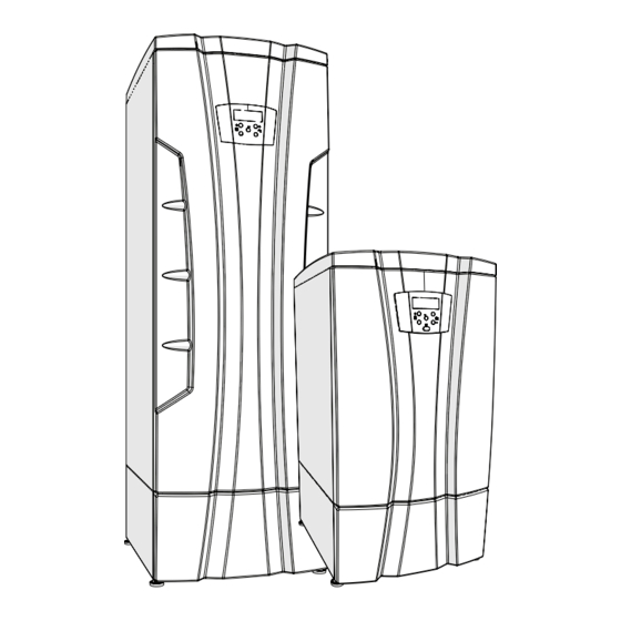
Gas condensing free-standing boiler
Hide thumbs
Also See for AGUADENS 60T:


Need help?
Do you have a question about the AGUADENS 60T and is the answer not in the manual?
Questions and answers