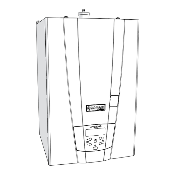
COSMOGAS MYDENS 60 Installation, Use And Maintenance Manual
Gas wall-mounted
condensing boiler
Hide thumbs
Also See for MYDENS 60:

Related Manuals for COSMOGAS MYDENS 60


Summary of Contents for COSMOGAS MYDENS 60
- Page 1 INSTALLATION, USE AND MAINTENANCE MANUAL MYDENS 60 GAS WALL-MOUNTED CONDENSING BOILER 62403579 - R00 28-11-2013_GB...
-
Page 2: Table Of Contents
6.4 - Conversion of the appliance from one type of gas to another ................33 6.5 - Ignition ..................................35 6.6 - Controlling the supply gas pressure and any adjustment ..................35 6.7 - Controlling the combustion agent air pressure ....................... 36 COSMOGAS MYDENS 60... -
Page 3: Index
12 - CE DECLARATION OF CONFORMITY ......................68 13 - HYDRAULIC TEST CERTIFICATE ......................69 14 - WARRANTY ..............................70 14.1 - General warranty conditions ..........................70 14.2 - Instructions for filling-in the warranty card ......................70 14.3 - Limits of the warranty ............................70 COSMOGAS MYDENS 60... -
Page 4: General Safety Recommendations
Worker Security and Protection”) lack of experience and knowledge, unless they have been given supervision or instruction concerning use of the appliance by a person responsible for their safety. COSMOGAS MYDENS 60... -
Page 5: General Information
This product has been developed thanks to the constant research by COSMOGAS, considered the “top” regarding respect for the environment, as it lies within class 5 (the least polluting) envisioned by the EN 297 (and EN 483) Technical Standard and has high efficiency;... -
Page 6: Main Components
9 - Primary heat exchanger 21 - Front casing 10 - Return fitting 22 - Display 11 - Air vent valve 23 - Control board 12 - Air intake and burned gas exhaust Figure 3.1 - Boiler internal components COSMOGAS MYDENS 60... - Page 7 34 - Burner 35 - Burner window 1005 36 - Left ignition electrode 27 - Central heating circuit pressure sensor 37 - Right ignition electrode 1007 28 - Return temperature sensor (Par. Figure 3.1 - Boiler internal components COSMOGAS MYDENS 60...
-
Page 8: Operation
22 = Condensate drain collector and of the safety valve 23 = Central heating plant 24 = Air vent valve 25 = Safety valve 26 = Water flow rate measuring device * Present only in model C Figure 4.1 - Hydraulic layout MYDENS 60A MYDENS 60C COSMOGAS MYDENS 60... -
Page 9: Operation And Intended Use Of The Appliance
A Indirect Water Heater must be connected for the production of domestic hot water, according to the layout in figure 4.7. The temperature of the domestic hot water is adjusted following the relevant procedure in chapter 7.8. COSMOGAS MYDENS 60... -
Page 10: Characteristic Curve Of The Residual Head At The Central Heating Plant
In this case, the field of modulation (detail “x”) can be verified on the graphics in figure 4.3. Figure 4.2 - Residual head for MYDENS 60C with 8 metre pump (standard) Figure 4.3 - Residual head for MYDENS 60C with modulating pump (on request) COSMOGAS MYDENS 60... -
Page 11: Head Losses Characteristic Curve
To do this, the flow resistances of the boiler are given in a graphical form in figure 4.4. Figure 4.4 - Flow resistance of the MYDENS “A” boiler COSMOGAS MYDENS 60... - Page 12 4 - OPERATION COSMOGAS MYDENS 60...
- Page 13 4 - OPERATION COSMOGAS MYDENS 60...
-
Page 14: Installation
1 - 1” 1/2 central heating flow 2 - 1” gas inlet 3 - 1” 1/2 central heating return 4 - Fumes exhaust/Air intake 5 - Support attachments Figure 5.2 - Boiler dimensions and attachments centre to centre distances COSMOGAS MYDENS 60... -
Page 15: Mounting The Appliance
4.- hang the boiler on the plugs “C”; 5.- make the hydraulic fittings. 5.5 - Flow and Return ATTENTION !!! COSMOGAS is not liable for any damage caused by incorrect use of additives in the central heating plant. ATTENTION !!! The plant downstream from the appliance must be made with materials that resist temperatures up to 97°C and pressure of 3 bar. -
Page 16: Water Supply
A slow drop in plant pressure due to a leak is often difficult to find, especially when the flaw is very small (in COSMOGAS MYDENS 60... -
Page 17: Treatment Of The Water In The Thermal Plants For Civil Use
20°C (see chapter 11). With this setting, the boiler will adjust the flow to a temperature between 20°C and 45°C. No adjustment from the command panel (also via climatic adjustment),can supply water at a temperature over 45°C. COSMOGAS MYDENS 60... -
Page 18: Condensate Drain
A = central heating flow Ø 35 B = central heating return Ø 35 Figure 5.6 - Siphon funnel (on request) C = 1” 1/2 flow fitting D = 1” 1/2 return fitting E = 1”1/2 Gasket COSMOGAS MYDENS 60... -
Page 19: Electric Connections: Generalities
DNC = External diverter valve (if present) (D = Domestic hot water line; N = Neutral; C = Heating line) L1 = boiler power supply line N = Boiler power supply neutral EARTH SYMBOL = Earth contacts 020002.01.009 020002.01.010 Figure 5.7 - Electric connections COSMOGAS MYDENS 60... -
Page 20: Power Supply Cable Connection
(25Vdc), they must flow in wires different from the - potential-free (not powered); 230 Vac power supplies. - closing when there is a request for heat; - 24Vac, 1A electrical feature Figure 5.8 - Correct positioning of the room thermostat/chronothermostat COSMOGAS MYDENS 60... -
Page 21: Installing The External Temperature Sensor (On Request)
The enabling of the external sensor is confirmed by the appearance of the icon on the display. Proceed with the steps given in chapter 7.11.3 to set the correct adjustment values of the flow temperature depending on the external temperature. COSMOGAS MYDENS 60... -
Page 22: Connection Of The Boiler With Indirect Water Heater And Coil
5 - INSTALLATION 5.15 - Connection of the boiler with Indirect Water Heater and coil The MYDENS 60 model boiler can be connected to a Indirect Water Heater with coil. The hydraulic connection must be made as in figure 4.7. -
Page 23: Burned Gas Exhaust And Combustion Agent Air Intake Pipe
ATTENTION !!! With the C63 type exhaust, the condensate coming from the chimney cannot be conveyed into the boiler. - C83, separated with wall intake or another point independent from the intakes of other appliances and flue exhaust. Figure 5.9 - Exhaust/intake systems COSMOGAS MYDENS 60... -
Page 24: Type Of Intake/Exhaust B23
the flow of air from the adjacent room to that to be ventilated can take place freely through permanent openings with total net section not less than that indicated at the start of this chapter. COSMOGAS MYDENS 60... -
Page 25: Split 80/80Pp" System (Polypropylene) (Type C43; C53; C83)
1 metre from each other. The brackets must be fixed to rigid walls that can support the weight of the pipe itself. Figure 5.12 - Fixing the exhaust and intake pipes COSMOGAS MYDENS 60... -
Page 26: Split 80/80Pp" System (Type C43; C53; C83): Accessories Available
62617240 - N° N° 14 flexible hose M.F. PP L=20m 62617241 - N°16 spacer for flexible hose 62617238 - N° 17 telescopic joint PP 62617242 - N° 15 T-fitting PP 62617246 - N° 13 45° bend M/F PP COD. 62617306 COSMOGAS MYDENS 60... -
Page 27: Split 80/80Pp" System (Type C43; C53; C83): Installation Examples
The condensate produced in the vertical pipe must all be conveyed into the boiler. The intake must slope towards the outside to prevent rain water entering. Figure 5.14 - Example of “80/80 PP System” installation COSMOGAS MYDENS 60... -
Page 28: 80/125Pp Vertical Coaxial" System (Polypropylene) (C13; C33)
1 metre of linear pipe. Every 45° bend has a loss equivalent to 0.5 m of pipe. Figure 5.16 - Quotes and hole centre to centre distances for coaxial drain pre-installation Figure 5.17 - Positioning the coaxial pipe COSMOGAS MYDENS 60... -
Page 29: 80/125Pp Coaxial" System: Accessories Available
62617322 - N° 6 45° coaxial bend M/F PP 62617323 - N° 7 Coaxial extension L 1m PP 62617255 62617325 - N° 3 coaxial PP roof terminal 62617324 - N° 5 coaxial PP wall terminal 62617321 62617322 62617323 62617324 62617325 COSMOGAS MYDENS 60... -
Page 30: 80/125Pp Coaxial" System: Installation Examples
When a coaxial exhaust is made (see figure 5.18), both vertical and horizontal, the exhaust pipe slope upwards in a way to make the condensate flow into the boiler. Figure 5.18 - Examples of coaxial pipe installation COSMOGAS MYDENS 60... -
Page 31: Operating
3.- use the funnel to slowly pour about 200 cm3 (a glass) of water; 4.- re-mount everything in reverse order. 020005.01.006 Figure 6.1 - Filling the condensate drain siphon COSMOGAS MYDENS 60... -
Page 32: General Recommendations Regarding The Supply Of Gas
(natural gas) at a supply pressure of 20 mbar. 3P-G31-37mbar L.P. GAS means that the appliance is adjusted to operate with type P gas (Propane, also called LP Gas) of the third family, at a supply pressure of 37 mbar. COSMOGAS MYDENS 60... -
Page 33: Conversion Of The Appliance From One Type Of Gas To Another
23. - check for any gas leaks using the relevant means of control. 020002.01.042 Perform the leak test using a ATTENTION !!! soap and water only. The use of naked flames is prohibited. Figure 6.4 - Replacing the gas nozzle COSMOGAS MYDENS 60... - Page 34 (mm) 3002 (mbar) (mbar) 10,0 9,0 ± 8,5 ± 4,9 ± 5,8 ± LP gas 10,5 ± 10,0 ± 4,8 ± 5,6 ± Figure 6.7 - Correspondence table for the parameter 3002 and the operating values COSMOGAS MYDENS 60...
-
Page 35: Ignition
17.- check for any gas leaks from the point with relevant control methods. ATTENTION !!! Perform the leak test using a soap and water only. The use of naked flames is prohibited. A - Gas inlet pressure point. Figure 6.8 - Gas valve COSMOGAS MYDENS 60... -
Page 36: Controlling The Combustion Agent Air Pressure
“A”, close the pipe 020002.01.020 “D” using cap “B” and close the pressure point “H” again as in figures 6.9 and 6.10. Figure 6.11 - Controlling combustion agent air pressure COSMOGAS MYDENS 60... -
Page 37: Controlling The Level Of Co2 And Any Adjustment
B - CO2 adjustment screw at minimum power; the value to 16.- press the RESET key to confirm the modification. 17.- hold the RESET key down for 5 seconds to exit the Figure 6.14 - Gas valve “installer” menu. COSMOGAS MYDENS 60... -
Page 38: Adjustment Of The Power In Central Heating Mode (Range Rated)
6.- Press the RESET key to confirm the modification. 7.- Hold the RESET key down for 5 seconds to exit the “installer” menu. Figure 6.15 - Corresponding values to introduce into the parameter 2002 to obtain the desired power necessary in central heating mode COSMOGAS MYDENS 60... -
Page 39: Use
R - Key for increasing the domestic hot water temperature and to scroll and change the value of the parameters S - Key for reducing the domestic hot water temperature and to scroll and change the value of the parameters T - On/Off switch COSMOGAS MYDENS 60... -
Page 40: Generalities
2020 rises above the value set in parameter (forced requirement of the plant. If the temperature tends to rise central heating switch-off), the central heating service ends. further, the burner stops. COSMOGAS MYDENS 60... -
Page 41: Thermostatic Adjustment
- large plants, with radiant panels (low temperature), where each area is controlled by its own room thermostat and the boiler pump is stopped only when all area thermostats are satisfied (envision the appropriate electric plant). COSMOGAS MYDENS 60... - Page 42 = Flow temperature corresponding to the spring-like external temperature 3016 Par. = Minimum flow temperature 3015 Par. = Maximum flow temperature = Line parallelism increase key = Line parallelism decrease key Figure 7.2 - Climatic adjustment graphics for “high temperature” plants (with radiators) COSMOGAS MYDENS 60...
-
Page 43: Climatic Adjustment: Adaptation To Different Climatic Areas
2 minutes; - Pumps anti-block and diverter valve: every 24 hours, the central heating pump, the domestic hot water pump (if present) and the diverter valve are forced; COSMOGAS MYDENS 60... -
Page 44: User Menu
1060 Interval of time between the last two blocks (Loc) value in days; value in weeks; 1061 Current rotation speed of the domestic hot water turbine 1062 Current domestic hot water flow rate l/min COSMOGAS MYDENS 60... -
Page 45: Installer Menu
Forcing of the central heating side diverter valve ON = in central heating mode; OFF = in D.H.W. mode 2013 Forcing of the domestic hot water side diverter valve ON = in D.H.W. mode; OFF = in central heating mode COSMOGAS MYDENS 60... - Page 46 RESE = Meter reset 2081 Periodic maintenance meter: maintenance request time days From 0 to 1000 1000 2100 Energy saving display OFF = display always on From 1 to 30 = delay to switch- off in minutes. COSMOGAS MYDENS 60...
-
Page 47: Diagnostics
Anti-legionella function running (see chapter 5.15.1). It will end on reaching the water temperature of 60°C inside the Indirect Water Heater temperature (°C) ALEg Indirect Water Heater. Maintenance request for the boiler Appliance temperature (°C) COSMOGAS MYDENS 60... -
Page 48: Diagnostics: Blocks "Loc
Clean and check efficiency again. Loc 15 Software error inside the Replace the command and control board. command board Loc 16 Software error inside the Replace the command and control board. command board COSMOGAS MYDENS 60... - Page 49 Loc 27 Software error inside the Replace the command and control board. command board Loc 28 Software error inside the Replace the command and control board. command board COSMOGAS MYDENS 60...
-
Page 50: Diagnostics: Errors "E
8.17. Check the The electric circuit must be repaired if it is damaged. electric cables for connection between the sensor Without either of the two previous cases, replace the and the command board. command and control board. COSMOGAS MYDENS 60... -
Page 51: Diagnostics: Alarms"Atte
0.6 must be replaced. If the plant has a leak it must be pressure too low for bar; check that there are no water leaks from the repaired. more than 10 minutes central heating plant. COSMOGAS MYDENS 60... -
Page 52: Maintenance
ATTENTION !!! Before every maintenance operation, disconnect the appliance from the electric power supply, using the relevant switch in the vicinity. ATTENTION !!! Close the gas cock before any maintenance operation COSMOGAS MYDENS 60... -
Page 53: Removing The Casing And Access To Internal Components
To access the electric connections board: 1.- turn the command board “D” towards the front; 2.- slide lid “E” out by operating on the closing flaps “F”; 020005.01.007 Figure 8.1 - removing the casing and opening of command board COSMOGAS MYDENS 60... -
Page 54: Removing The Burner Fan Unit
9.- check that there are no gas leaks between the joints removed; ATTENTION !!! Perform the leak test using a soap and water only. The use of naked flames is prohibited. 020005.01.008 Figure 8.2 - Removing the burner fan unit COSMOGAS MYDENS 60... -
Page 55: Correct Positioning Of The Ignition And Ionising Electrodes
6.- extract the safety valve “A” upwards and replace it by restoring the drain pipe of the same as it was previously mounted. Figure 8.4 - Removing the flow meter 020005.01.009 Figure 8.5 - Removing the safety valve COSMOGAS MYDENS 60... -
Page 56: Cleaning The Condensate Conveyor Siphon
“G” is introduced correctly in the seat “H”; siphon 10.- restore the level of liquid inside the siphon following the procedure in chapter 6.1.2. 020002.01.030 02002.01.029 Figure 8.7 - Removal of the condensate collection Figure 8.8 - Condensate collection siphon siphon COSMOGAS MYDENS 60... -
Page 57: Removing The Air Vent Valve
5.- slide out and extract the pressure sensor “A” from the fitting “C”, as indicated in the figure. 6.- replace the sensor, restoring the connections as previously. Figure 8.11 - Removing the central heating circuit pressure sensor COSMOGAS MYDENS 60... -
Page 58: Emptying The Appliance
To go back to normal supplied by the boiler is much higher than the power absorbed by the plant, the boiler switches off 2010 0FF. operating conditions, set parameter again to continuously to reach the maximum temperature allowed (93°C). COSMOGAS MYDENS 60... -
Page 59: Checking The Ionisation Current
On request, the external temperature sensor can be 1004 connected to the boiler (see chapter 5.14.4). The electric resistance existing between the two contacts of the sensor, must correspond with that stated in figure 8.13. Figure 8.13 - External temperature sensor curve COSMOGAS MYDENS 60... -
Page 60: Operational Wiring Diagram
(see example above) to EA - Ignition electrode identify the correct follow-on of the ER - Detection electrode cables in the next page. F (PWM) - Fan F (BCU) - 5A fuse Figure 8.14 - Operational wiring diagram COSMOGAS MYDENS 60... - Page 61 VG1- Gas Valve J26- 4 pin Molex connector J3 - 12 pin Molex connector J4 - 4 pin Stelvio connector J5 - 16 pin Molex connector J6 - 14 pin Molex connector J7- 10 pin Molex connector COSMOGAS MYDENS 60...
-
Page 62: Multi-Wire Wiring Diagram
8 - MAINTENANCE 8.20 - Multi-wire wiring diagram Key - see key figure 8.14 Figure 8.15 - Multi-wire wiring diagram COSMOGAS MYDENS 60... - Page 63 8 - MAINTENANCE COSMOGAS MYDENS 60...
-
Page 64: Technical Data
N.A. N.A. Instantaneous D.H.W. adjustment range °C N.A. N.A. D.H.W. with Indirect Water Heater adjustment range °C 40 - 70 40 - 70 Design temperature °C Maximum central heating temperature °C Minimum central heating temperature °C COSMOGAS MYDENS 60... - Page 65 Fumes maximum temperature for overheating °C Max. negative pressure allowed in the fumes exhaust/intake system Condensate maximum flow rate Condensate average acidity Operating environment temperature °C 0 ; + 50 0 ; + 50 Weight of the boiler COSMOGAS MYDENS 60...
-
Page 66: Command Menu Diagram
(see conditions chapter 7.18) (see chapter 7.19) User menu parameters (see chapter 7.17) Return to normal operation Return to normal operation Figure 10.1 - Command menu diagram COSMOGAS MYDENS 60... -
Page 67: Menu Forced By Internal Electric Bridge
1 = DN 8; Domestic hot water flow rate 2 = DN 10; 3020 sensor 3 = DN 15; 4 = DN 20; (MYDENS 60) 5 = DN 25; 0 = Disabled; 1 = Enabled; 3021 2nd Fumes sensor (1014) 2 = Enabled with fumes exhaust anti- closure pressure switch;... -
Page 68: Ce Declaration Of Conformity
12 - CE DECLARATION OF CONFORMITY The undersigned COSMOGAS S.r.L., with Registered Office in via L. Da Vincin° 16 - 47014 Meldola (FC) ITALY, DECLARES under its own responsibility that the product: WARRANTY N° MODEL MANUFACTURE subject of this declaration, is in compliance with the model described in the Type examination certificate, whose reference is given in the table in chapter 9 under “CE type certificate (PIN)”... -
Page 69: Hydraulic Test Certificate
13 - HYDRAULIC TEST CERTIFICATE HYDRAULIC TEST CERTIFICATE Under the Ministerial Decree December 1st, 1975 art. 17, the company COSMOGAS srl manufacturer of base and wall mounted boilers using gaseous fuels, CERTIFIED that this heat generator: Refer to the identification data of the product (WARRANTY N°, MODEL and MANUFACTURE) -
Page 70: Warranty
The faulty material replaced under warranty is COSMOGAS does not assume any responsibility for the property of COSMOGAS and must be returned to our any accident that may occur or be caused by the user, establishment, without further damage, within 30 days from precluding any compensation that does not concern boiler replacement. - Page 72 COSMOGAS s.r.l. Via L. da Vinci 16 - 47014 MELDOLA (FC) ITALY info@cosmogas.com www.cosmogas.com...
Need help?
Do you have a question about the MYDENS 60 and is the answer not in the manual?
Questions and answers