Viessmann Vitoflex 300-UF 530 Installation And Operating Instructions Manual
Wood-fired boiler
Hide thumbs
Also See for Vitoflex 300-UF 530:
- Service and maintenance instructions (24 pages) ,
- Installation and operating instructions manual (76 pages) ,
- Service and maintenance instructions (36 pages)
Table of Contents
Advertisement
Quick Links
Installation and
Operating Instructions
for use by engineers and heating contractors
Vitoflex 300-UF 390, 530, 720, 950 AND 1250
Wood-fired Boiler
Output range: UF 390, 334 to 1331 kW
UF 530, 450 to 1808 kW
UF 720, 614 to 2457 kW
UF 950, 812 to 3242 kW
UF 1250, 1065 to 4265 kW
Vitoflex 300-UF
5603 882 - 04
03/2017
H
IMPORTANT
Please ensure that these instructions are
read and understood before commencing
installation and start-up. Failure to comply
with these Installation Instructions will
render all warranties null and void.
Working on the equipment
The installation, adjustment, service and
maintenance of this product must be
performed by a licensed professional heating
contractor, who is qualified and
experienced in the installation, service
and maintenance of hot water heating
boilers. There are no user serviceable
parts on the boiler or control.
Ensure main power supply to equipment,
the heating system and all external
controls has been deactivated.
Take precautions in all instances to avoid
accidental activation of power during
service work.
Improper installation, service or
maintenance can cause product/property
damage, severe personal injury, and/or
loss of life.
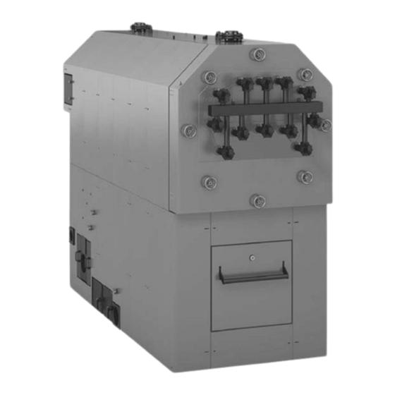
Product may not be exactly as shown
IMPORTANT
Read and save these instructions
.
for future reference
Please file in Service Binder
Advertisement
Table of Contents

Related Manuals for Viessmann Vitoflex 300-UF 530


Summary of Contents for Viessmann Vitoflex 300-UF 530
- Page 1 Installation and Operating Instructions for use by engineers and heating contractors Vitoflex 300-UF 390, 530, 720, 950 AND 1250 Wood-fired Boiler Output range: UF 390, 334 to 1331 kW UF 530, 450 to 1808 kW UF 720, 614 to 2457 kW UF 950, 812 to 3242 kW UF 1250, 1065 to 4265 kW Vitoflex 300-UF...
-
Page 2: Introduction
“Safety” section. All inhabitants and destructive to Viessmann equipment. products of combustion must be safely vented to the outdoors. For a listing of chemicals which... -
Page 3: About These Instructions
This symbol indicates that other instructions must be referenced. Note: Viessmann Manufacturing Company Inc. reserves the right to make product changes or updates without notice and will not be held liable for typographical errors or omissions in the product... -
Page 4: Table Of Contents
Table of Contents Vitoflex 300-UF Installation & Operating Page Introduction Safety, Installation and Warranty Requirements....2 About These Instructions..........3 General Information Important Regulatory and Installation Requirements ..6 Codes..............6 Mechanical room...........6 Working on the equipment........6 Technical literature..........6 Product Information.............7 Boiler Description............8 Transport and Installation..........9 Lifting..............9 Delivery Condition.............10 Standard delivery condition........10... - Page 5 Table of Contents Vitoflex 300-UF Installation & Operating Page Mechanical Fire Extinguishing System.........32 (continued) Assembly of the Fire Extinguishing System....33 Negative Pressure Monitoring Assembly......34 Electrical Control Panel............35 Mounting of control panel........35 Electrical connection..........35 General safety instructions........35 Vitocontrol-C boiler control UF......36 Electrical Components..........38 Fuel Transport and Extraction Systems......40 Rotary valve............40...
-
Page 6: General Information
Literature applicable to all aspects of the Vitoflex 300-UF Leave all literature at the installation site and advise wood-fired boiler: the system operator/ultimate owner where the literature can be found. Contact Viessmann for - Installation and Operating Instructions additional copies. - Service and Maintenance Instructions - Field Wiring Diagram ... -
Page 7: Product Information
General Information Vitoflex 300-UF Installation & Operating Product Information Viessmann solid-fuel boiler may only be installed and Maximum allowable working pressure (water)...30 or 60 psi serviced by trained personnel. Maximum water temperature…..250°F (120°C) (closed loop) Steel wood-fired hot water heating boiler. -
Page 8: Boiler Description
General Information Vitoflex 300-UF Installation & Operating Boiler Description Supplied with: Description The Vitoflex 300-UF Grate Firing System (patent no: EP - Boiler with combustion chamber and pressure vessel/ 0 905 442 B1) was developed for automatic combustion heat exchanger including supply and return of all dry to moist wood fuels (remnant wood, pellets and temperature sensors and over pressure monitor forest wood chips to max. -
Page 9: Transport And Installation
General Information Vitoflex 300-UF Installation & Operating Transport and Installation IMPORTANT Precautions must be taken to avoid accidents and injury during the transportation of the boiler. Only hoist the boiler when it is entirely empty of water, fuel and ash. Lifting The combustion chamber has four lifting lugs that must be screwed in before lifting. -
Page 10: Delivery Condition
General Information Vitoflex 300-UF Installation & Operating Delivery Condition Standard delivery condition The standard delivery condition of the Vitoflex 300-UF boiler includes pre-assembled components as well as components that need to be assembled by the contractor in the field. Components that are attached to the boiler at time of delivery: - Heat exchanger door is mounted to the heat exchanger - Combustion chamber door is mounted to the combustion chamber - Flue gas collector is attached to the heat exchanger... -
Page 11: Wood Fuel Requirements
The Vitoflex 300-UF is only suitable for burning fuels IMPORTANT listed in this section. A prerequisite for approval is of a fuel by Viessmann is the approval for the fuel by the If different fuels are used, Viessmann will not assume any responsible public authorities. -
Page 12: Non-Wood Fuels
General Information Vitoflex 300-UF Installation & Operating Wood Fuel Requirements (continued) Maximum water content The maximum allowable water content of the fuel for Vitoflex 300-UF systems is limited to 50%. The water content impacts the maximum boiler output. Non-wood fuels Non-wood fuels even if consisting of biomass, such as needles, foliage, grain, straw, fruit pits, etc, are unsuited as fuel for boiler operation and may not be used. -
Page 13: Content Limits For Non-Combustable Substances
General Information Vitoflex 300-UF Installation & Operating Wood Fuel Requirements (continued) Content limits for non-combustible substances - No wood fuels may contain any foreign bodies, such as pieces of metal, stones, masonry remnants or plastics. The following limits (per mg/kg of dry fuel) of contained non-combustible substances apply [ash analyzed at a temperature of 1500°F (815°C)]: Substance Limit... -
Page 14: Safety
Failure to heed this warning can cause property damage, Note: Viessmann does not test any detectors and makes severe personal injury, or loss of life. no representation regarding any brand or type of detector. -
Page 15: Hazardous Materials
Safety Vitoflex 300-UF Installation & Operating Hazardous Materials Fiberglass wool and ceramic fiber materials Suppliers of ceramic fiber products recommend the following first aid measures WARNING - Respiratory tract (nose and throat) irritation: If respiratory tract irritation develops, move the Inhaling of fiberglass wool and/or ceramic fiber person to a dust free location. -
Page 16: Power Failure Provision
Safety Vitoflex 300-UF Installation & Operating Power Failure Provision Power Failure Provision Customers must ensure that there is a supply of water independent of the electrical supply. This design ensures that in case of a power failure, the boiler will be reliably cooled by the thermal safety flush valve. -
Page 17: Mechanical Room
The load-bearing capacity of the floor in Viessmann recommends the installation of an additional the area of the boiler bearing surface must be 512 lb/ft² electrical disconnect switch and a fuel shut-off valve (if (2500 kg/m²). -
Page 18: Mechanical Room Conditions
Safety Vitoflex 300-UF Installation & Operating Mechanical Room (continued) IMPORTANT WARNING Components which are not tested with the heating Incorrect ambient conditions can lead to damage to system may damage the heating system or affect its the heating system and put safe operation at risk. functions. -
Page 19: Combustion Air Supply
Safety Vitoflex 300-UF Installation & Operating Combustion Air Supply Codes Confined spaces Provision for combustion and ventilation air must be made When a furnace or boiler is enclosed in a space that has in accordance with applicable local codes. a volume less than 20% of that to be heated by the In the absence of local codes, use: appliance, the space shall: CSA B365-10, Installation Code for Solid Fuel Burning... -
Page 20: Mechanical
Mechanical Vitoflex 300-UF Installation & Operating Technical Data Boiler model UF 390 UF 530 UF 720 UF 950 UF 1250 Maximum output MBH (kW) 1331 (390) 1808 (530) 2457 (720) 3242 (950) 4265 (1250) Minimum output MBH (kW) 334 (98) 450 (132) 614 (180) 812 (238) -
Page 21: Boiler Dimensions
Mechanical Vitoflex 300-UF Installation & Operating Specifications Boiler Dimensions BR Boiler Return BS Boiler Supply Dimensions Boiler Model UF 390 UF 530 UF 720 UF 950 UF 1250 in. (mm) (2378) (2536) (2834) (3035) (3230) 5 / 8 7 / 8 5 / 8 ½... -
Page 22: Boiler Components
Mechanical Vitoflex 300-UF Installation & Operating Boiler Dimensions (continued) Legend A Boiler return B Motor for de-ashing assembly with ash container E Secondary air blower (optional) F In-feed auger C Primary air blower 1 D Boiler supply Dimensions Boiler Model UF 390 UF 530 UF 720... -
Page 23: Flue Gas Cyclone
Mechanical Vitoflex 300-UF Installation & Operating Flue Gas Cyclone The flue gas cyclone minimizes dust emissions and is Supplied with: designed as a multi cyclone with axial function. The - 1 flue gas cyclone cyclone is fully insulated and has three covers for cleaning. - 1 ash container 63 USG (240L) or 211 USG (800L) The crude gas chamber is cleaned via the side cleaning cover. -
Page 24: Recirculation System
Mechanical Vitoflex 300-UF Installation & Operating Recirculation System... - Page 25 Mechanical Vitoflex 300-UF Installation & Operating Recirculation System (continued) Item Boiler Model UF 390 UF 530 UF 720 UF 950 UF 1250 Description Quantity Quantity Quantity Quantity Quantity Pipe adaptor primary air 1 Pipe adaptor primary air 2 Elbow 130 x 0.9/90° with PD Flue damper blade D=5d in.
-
Page 26: Safety Devices
Mechanical Vitoflex 300-UF Installation & Operating Safety Devices Expansion 1. Install the pressure relief valve, discharge pipe, air vent and pressure gauge as illustrated in section piping With closed expansion, the supply pressure to the and installation of safety devices. expansion tank should be equal to the max. - Page 27 Mechanical Vitoflex 300-UF Installation & Operating Safety Devices (continued) The safety equipment for the heating installation must be installed by a heating contractor authorized to do so. Legend A Nipple, c in. x 1b in. P Pressure relief valve, 30 psi or 60 psi B Reducing coupling, c in.
-
Page 28: Piping And Installation Of Safety Devices
Mechanical Vitoflex 300-UF Installation & Operating Piping and Installation of Safety Devices System fill Drain inspection port System fill Safety heat exchanger top view 3-Way mixing valve System return line Blocked 4 heat port exchanger Bypass line loops and 2 TS2430 for Vitoflex 300- UF 720, 950... - Page 29 122 - 248°F (50 - 120°C), (safety Note: The UF 1250, 30 psi will have 2 PRVs. heat exchanger loop built into boiler). The Vitoflex 300-UF 390 and Vitoflex 300-UF 530 have two safety heat exchanger loops and require one thermal safety flush valve.
-
Page 30: Fire Protection
UPS 80-160 F 60 Hz 3 x 208-230V UF 1250 TP 100-80/4 60 Hz 3 x 208-230 / 460V Mixing valve Viessmann ASME recommended tank sizes (U-stamped) Boiler model Nominal Valve Boiler model Tank size pipe size UF 390 3 in. -
Page 31: Back-Burn Safeguard For The Fuel Supply System
Fire protection for fuel storage space unit and the boiler. The rotary valve is suited to reduce pressure and at the same time is considered a suitable Viessmann does not provide fire protection for the fuel safeguard against back-burn. storage space. -
Page 32: Fire Extinguishing System
Mechanical Vitoflex 300-UF Installation & Operating Fire Extinguishing System The fire extinguishing system functions independent from Fire extinguishing system for the conveyor auger the electrical power and is flooding the material which is Note: The fire extinguishing system for the conveyor still remaining in the in-feed auger in case of back-burn. -
Page 33: Assembly Of The Fire Extinguishing System
Mechanical Vitoflex 300-UF Installation & Operating Assembly of the Fire Extinguishing System deburr drill hole Connection to the extinguishing water container or cold water supply piping (field supplied). Item No. Quantity Description Item No. Quantity Description Floater switch (N25) Connector b in. Washer Danfoss AVTA Hex nut M6... -
Page 34: Negative Pressure Monitoring Assembly
Mechanical Vitoflex 300-UF Installation & Operating Assembly of the Fire Extinguishing System (continued) The following assembly instructions for the fire Note: The Weld on nipple (18) is pre-installed at the extinguishing system are to be used with the layout metering container. The Weld on nipple (18) needs and description shown on page 31. -
Page 35: Electrical
The minimum temperature must not be less than 50°F (10°C) In case of doubt, preference should be given to The Viessmann supplied field wiring diagram is not a placing the control panel outside the mechanical room complete system drawing. It is the installer’s responsibility near the heating room door. -
Page 36: Vitocontrol-C Boiler Control Uf
Electrical Vitoflex 300-UF Installation & Operating Control Panel (continued) Vitocontrol - C, boiler control UF Mains supply 208V, 3 phase, 60 Hz, see field wiring diagram for details. Customer terminal tag Description Line voltage connections 24V connections Dry contact outputs Alarm outputs... - Page 37 Electrical Vitoflex 300-UF Installation & Operating Control Panel (continued) Device tags and designations may vary from project to project. Please refer to the field wiring diagram for details. The wiring diagram will be supplied after the control panel is built or with the receipt of the control panel. Components Installed in the Control Panel Components Installed in the Control Panel Device tag...
-
Page 38: Electrical Components
Electrical Vitoflex 300-UF Installation & Operating Electrical Components... - Page 39 Electrical Vitoflex 300-UF Installation & Operating Electrical Components (continued) M High voltage B sensors N Sensors Y Low voltage S Switches High Voltage Number Designation Device tag Description -3M1 Flue gas exhaust blower (not shown) -9M11 Grate drive -13M13 Secondary air blower (not shown) -14M14 De-ashing auger -15M15...
-
Page 40: Fuel Transport And Extraction Systems
Electrical Vitoflex 300-UF Installation & Operating Fuel Transport and Extraction Systems Rotary Valve Number Designation Device tag Description -9 M9 Motor for rotary valve... -
Page 41: In-Feed Auger
Electrical Vitoflex 300-UF Installation & Operating Fuel Transport and Extraction Systems (continued) In-feed auger Number Designation Device tag Description -4M2 Motor for in-feed auger -68S2 Limit switch for maintenance lid B31.1 -11B31.1 Light barrier metering container (Transmitter) B31.2 -11B31.2 Light barrier metering container (Receiver) M10.1 -8M10.1 Slide valve T30... -
Page 42: Pellet Extraction Auger
Electrical Vitoflex 300-UF Installation & Operating Fuel Transport and Extraction Systems (continued) Pellet extraction auger Number Designation Device tag Description -12M32 Motor for pellet extraction auger S32.1 -12S32.1 Limit switch for maintenance lid S32.2 -12S32.2 Limit switch for silo door (not shown) Note: For details on designation see field wiring diagram. -
Page 43: Horizontal Extraction System
Electrical Vitoflex 300-UF Installation & Operating Fuel Transport and Extraction Systems (continued) Horizontal extraction system Number Designation Device tag Description -12M32 Motor for extraction auger -12M33 Motor for agitator -12B32 Light barrier for extraction auger S32.1 -12S32.1 Safety switch for maintenance lid S32.2 -12S32.2 Safety switch for silo door (not shown) -
Page 44: Walking Floor Auger
Electrical Vitoflex 300-UF Installation & Operating Fuel Transport and Extraction Systems (continued) Walking floor auger Number Designation Device tag Description -4M2 Motor for walking floor auger -68S3 Safety switch for maintenance lid S3.1 -68S3.1 Safety switch for auger cover B3/1 -61B3/1 Light barrier walking floor auger (Transmitter) B3/2... -
Page 45: Thermal Storage Tank
Electrical Vitoflex 300-UF Installation & Operating Fuel Transport and Extraction Systems (continued) Silo Lid Number Designation Device tag Description Y6.3 -22Y6.3 Solenoid valve silo lid open Y6.4 -22Y6.4 Solenoid valve silo lid close S6.1 -22S6.1 Key operated switch for silo lid M901 -24M901 Vibration motor 1... -
Page 46: Boiler Wiring
Boiler Wiring CAUTION CAUTION The Viessmann supplied field wiring diagram is not a The information about wire type, wire number and wire complete system drawing. It is the installer’s responsibility gauge made in the wiring diagrams is not obligatory. The... -
Page 47: Operation
Commissioning Initial startup Oxygen diffusion barrier under floor tubing Only a Viessmann or another trained specialist may put The boiler warranty does not cover pressure vessel failure a newly installed system into operation for the first time. resulting from corrosion caused by the use of underfloor Before the system is commissioned, the system must be plastic tubing without an oxygen diffusion barrier. -
Page 48: Filling The Fuel Storage Unit
Heating system not in operation: will be turned on. - If the articulated arms or spring-mounted plates are still Note: Viessmann recommends the installation of carbon covered by fuel, refilling can be carried out immediately. monoxide detector(s) inside the fuel storage area. -
Page 49: Excess Conditions
Operation Vitoflex 300-UF Installation & Operating Excess Conditions Low water/excess water pressure Excess temperature/power failure Possible causes: CAUTION Low water: Leakage in the heating system. Excess water pressure: The expansion tank is not DANGER OF THIS EQUIPMENT SUDDENLY GOING UP functioning. -
Page 50: Boiler Control Control System
Operation Vitoflex 300-UF Installation & Operating Boiler Control System The control system for the Vitoflex 300-UF boiler firing The soft touch keys in Screen 1 process (boiler control) is controlled by a Programmable Switch on boiler Logic Controller (PLC), which visualizes the system on a When touched, the color changes touch screen and provides an interface for navigation and (from light to dark) -
Page 51: Touch Screen, Screen 1-8
Navigation: The navigation program “boiler control” is Settings can be changed in screen 1-8 by touching the a product of Viessmann Manufacturing Company Inc. respective soft touch key. This opens new windows It is operated following the same patterns like MS with new input fields or soft touch keys. -
Page 52: Screen 1, Object Indicator Light
Operation Vitoflex 300-UF Installation & Operating Boiler Control System (continued) The following applies to all screens. The screen title Screen 1, Object indicator light and user status are shown at the top. The screen title Displays operational status of boiler pump and additional indicates which Screen (1-8) is active. -
Page 53: Screen 2, Alarm List
Operation Vitoflex 300-UF Installation & Operating Boiler Control System (continued) Screen 2, Alarm list Touching the red Alarm line soft touch key (in Screen Touching an alarm log line allows the respective error 1) opens Screen 2 (Alarm List with alarm logs, red). All message to be displayed in detail or acknowledged. -
Page 54: Screen 3, Managing The User Status
Administrator, access to Win CE Desktop as well as software updating possible By introducing these user levels, Viessmann is making an effort to maintain the parameters essential for quality-assured businesses. This guarantees good operational practice, as certain parameter changes are reserved only for Viessmann technicians. -
Page 55: Screen 4, Adjusting Settings And Parameters
Operation Vitoflex 300-UF Installation & Operating Boiler Control System (continued) Screen 4, Adjusting settings and process parameters In the Settings menu, adjustable categories can be The new value is immediately valid in the furnace firing chosen and their parameters changed. and/or heat recovery process. -
Page 56: Screen 7, Overview Wood Powered Boiler
Operation Vitoflex 300-UF Installation & Operating Boiler Control System (continued) Screen 7, Overview, wood-powered boiler Touching the Vitoflex 300-UF Boiler soft touch key (photo (For explanation on the text display, see “Operating modes”). in Screen 1) opens Screen 7 (sectional view of the boiler). Measurement operation, emergency operation and the Here the most important process parameters, activity modes activity of the de-ashing assembly with ash container as... -
Page 57: Screen 8, Additional Boilers
Operation Vitoflex 300-UF Installation & Operating Boiler Control System (continued) Screen 8, Additional boilers When the soft touch key for additional boilers is touched (For explanation on the text displays, see “Operating modes”). (symbol in Screen 1), Screen 8 opens (symbol for oil or Here the additional boiler can be manually switched on gas boiler, enlarged). -
Page 58: Vitoflex 300-Uf Control System Parameters
Operation Vitoflex 300-UF Installation & Operating Boiler Control System (continued) Vitoflex 300-UF control system parameter Parameters boiler Unit Min. Max. Default Detailed definition 1 Boiler temperature, °C 85.0 Set point for supply temperature, system design forward(out) flow temperature 2 Boiler temperature, return(in) °C 70.0 Set point for return temperature... -
Page 59: Guide For The Technician
Operation Vitoflex 300-UF Installation & Operating Boiler Control System (continued) Vitoflex 300-UF controller parameter reference guide for the technician Regulator temperature Unit Min. Max. Default Detailed definition Hysteresis(lagging behind) °C 10.0 Value is calculated by value in 7 + value in 9, standby (boiler off) ON puts boiler in standby mode, when boiler is On. - Page 60 Operation Vitoflex 300-UF Installation & Operating Boiler Control System (continued) Vitoflex 300-UF controller parameter reference guide for the technician (continued) Fuel loading Unit Min. Max. Default Detailed definition Extraction system direction of advance On/Off Changes direction of extraction system Switch-on delay for hydraulic system Sec.
- Page 61 Operation Vitoflex 300-UF Installation & Operating Boiler Control System (continued) Vitoflex 300-UF controller parameter reference guide for the technician (continued) Accumulator management system Unit Min. Max. Default Detailed definition Starts boiler when temperature falls B28.1 B28.1 Sensor used to start boiler when below below selected sensor in acc B28.5 value in 4...
-
Page 62: Operating Modes
Operation Vitoflex 300-UF Installation & Operating Operating Modes The following terms are displayed in the operating mode line depending on the situation. The boiler is switched off. Filling Cold start. The combustion chamber trough is being filled by the underfeed auger. -
Page 63: Full Load Operation
Operation Vitoflex 300-UF Installation & Operating Operating Modes (continued) Full load operation Transition in output As soon as a combustion chamber temperature of To obtain a good structure of the fire and thus low approximately 356°F (180°C) is reached (adjustable value), emissions of harmful substances, the switchover from the system switches, depending on the boiler temperature, “SUSTAIN”... -
Page 64: Heating Up Manually
Vitoflex 300-UF Installation & Operating Heating Up Manually Filling the burner trough Check heat up successful When the system has been switched off properly, there is The combustion chamber temperature should be over no more fuel in the burner trough or in the underfeed auger. 356°F (180°C) in 30 minutes (adjustable value).
Need help?
Do you have a question about the Vitoflex 300-UF 530 and is the answer not in the manual?
Questions and answers