Viessmann Vitoflex 300-UF Series Installation And Operating Instructions Manual
Wood-fired boiler
Hide thumbs
Also See for Vitoflex 300-UF Series:
- Technical manual (100 pages) ,
- Operating instructions manual (57 pages) ,
- Service and maintenance instructions (36 pages)
Table of Contents
Advertisement
Quick Links
Installation and
Operating Instructions
for use by engineers and heating contractors
Vitoflex 300-UF 390, 530, 720, 950 AND 1250
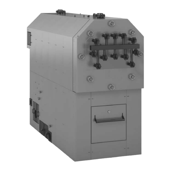
Wood-fired Boiler
Output range: UF 390, 334 to 1331 MBH (98 to 390 kW)
UF 530, 450 to 1808 MBH (132 to 530 kW)
UF 720, 614 to 2457 MBH (180 to 720 kW)
UF 950, 812 to 3242 MBH (238 to 950 kW)
UF 1250, 1065 to 4265 MBH (312 to 1250 kW)
Vitoflex 300-UF
5797 344 - 01 08/2017
H
IMPORTANT
Please ensure that these instructions are
read and understood before commencing
installation and start-up. Failure to comply
with these Installation Instructions will
render all warranties null and void.
Working on the equipment
The installation, adjustment, service and
maintenance of this product must be
performed by a licensed professional heating
contractor, who is qualified and
experienced in the installation, service
and maintenance of hot water heating
boilers. There are no user serviceable
parts on the boiler or control.
Ensure main power supply to equipment,
the heating system and all external
controls has been deactivated.
Take precautions in all instances to avoid
accidental activation of power during
service work.
Improper installation, service or
maintenance can cause product/property
damage, severe personal injury, and/or
loss of life.
Product may not be exactly as shown
IMPORTANT
Read and save these instructions
.
for future reference
Please file in Service Binder
Advertisement
Table of Contents

Related Manuals for Viessmann Vitoflex 300-UF Series


Summary of Contents for Viessmann Vitoflex 300-UF Series
- Page 1 Installation and Operating Instructions for use by engineers and heating contractors Vitoflex 300-UF 390, 530, 720, 950 AND 1250 Wood-fired Boiler Output range: UF 390, 334 to 1331 MBH (98 to 390 kW) UF 530, 450 to 1808 MBH (132 to 530 kW) UF 720, 614 to 2457 MBH (180 to 720 kW) UF 950, 812 to 3242 MBH (238 to 950 kW) UF 1250, 1065 to 4265 MBH (312 to 1250 kW)
-
Page 2: Safety, Installation And Warranty Requirements
“Safety” section. All inhabitants and destructive to Viessmann equipment. products of combustion must be safely vented to the outdoors. For a listing of chemicals which... -
Page 3: Introduction
This symbol indicates that other instructions must be referenced. Note: Viessmann Manufacturing Company Inc. reserves the right to make product changes or updates without notice and will not be held liable for typographical errors or omissions in the product... -
Page 4: Table Of Contents
Table of Contents Vitoflex 300-UF Installation & Operating Page Introduction Safety, Installation and Warranty Requirements....2 About These Instructions..........3 Important Regulatory and Installation Requirements ..6 General Information Codes..............6 Mechanical room...........6 Working on the equipment........6 Technical literature..........6 Product Information.............7 Boiler Description............8 Transport and Installation..........9 Lifting..............9 Delivery Condition.............10 Standard delivery condition........10... - Page 5 Table of Contents Vitoflex 300-UF Installation & Operating Page Mechanical Fire Extinguishing System.........32 (continued) Assembly of the Fire Extinguishing System....33 Negative Pressure Monitoring Assembly......34 Appliance Description..........35 Operating States............37 Commissioning............37 Electrical Control Panel............38 Mounting of control panel........38 Electrical connection..........38 General safety instructions........38 Programming Programming Unit............39 Default Display............40...
-
Page 6: General Information
Literature applicable to all aspects of the Vitoflex 300-UF Leave all literature at the installation site and advise wood-fired boiler: the system operator/ultimate owner where the literature can be found. Contact Viessmann for - Installation and Operating Instructions additional copies. - Service and Maintenance Instructions - Field Wiring Diagram ... -
Page 7: Product Information
General Information Vitoflex 300-UF Installation & Operating Product Information Viessmann solid-fuel boiler may only be installed and Maximum allowable working pressure (water)...30 or 60 psi serviced by trained personnel. Maximum water temperature…250°F (120°C) (closed loop) Steel wood-fired hot water heating boiler. -
Page 8: Boiler Description
General Information Vitoflex 300-UF Installation & Operating Boiler Description Supplied with: Description The Vitoflex 300-UF Grate Firing System (patent no: EP - Boiler with combustion chamber and pressure vessel/ 0 905 442 B1) was developed for automatic combustion heat exchanger including supply and return of all dry to moist wood fuels (remnant wood, pellets and temperature sensors and over pressure monitor forest wood chips to max. -
Page 9: Transport And Installation
General Information Vitoflex 300-UF Installation & Operating Transport and Installation IMPORTANT Precautions must be taken to avoid accidents and injury during the transportation of the boiler. Only hoist the boiler when it is entirely empty of water, fuel and ash. Lifting The combustion chamber has four lifting lugs that must be screwed in before lifting. -
Page 10: Delivery Condition
General Information Vitoflex 300-UF Installation & Operating Delivery Condition Standard delivery condition The standard delivery condition of the Vitoflex 300-UF boiler includes pre-assembled components as well as components that need to be assembled by the contractor in the field. Components that are attached to the boiler at time of delivery: - Heat exchanger door is mounted to the heat exchanger - Combustion chamber door is mounted to the combustion chamber - Flue gas collector is attached to the heat exchanger... -
Page 11: Wood Fuel Requirements
The Vitoflex 300-UF is only suitable for burning fuels IMPORTANT listed in this section. A prerequisite for approval is of a fuel by Viessmann is the approval for the fuel by the If different fuels are used, Viessmann will not assume any responsible public authorities. -
Page 12: Non-Wood Fuels
General Information Vitoflex 300-UF Installation & Operating Wood Fuel Requirements (continued) Maximum water content The maximum allowable water content of the fuel for Vitoflex 300-UF systems is limited to 50%. The water content impacts the maximum boiler output. Non-wood fuels Non-wood fuels even if consisting of biomass, such as needles, foliage, grain, straw, fruit pits, etc, are unsuited as fuel for boiler operation and may not be used. -
Page 13: Content Limits For Non-Combustable Substances
General Information Vitoflex 300-UF Installation & Operating Wood Fuel Requirements (continued) Content limits for non-combustible substances - No wood fuels may contain any foreign bodies, such as pieces of metal, stones, masonry remnants or plastics. The following limits (per mg/kg of dry fuel) of contained non-combustible substances apply [ash analyzed at a temperature of 1500°F (815°C)]: Substance Limit... -
Page 14: Safety
Failure to heed this warning can cause property damage, Note: Viessmann does not test any detectors and makes severe personal injury, or loss of life. no representation regarding any brand or type of detector. -
Page 15: Hazardous Materials
Safety Vitoflex 300-UF Installation & Operating Hazardous Materials Fiberglass wool and ceramic fiber materials Suppliers of ceramic fiber products recommend the following first aid measures WARNING - Respiratory tract (nose and throat) irritation: If respiratory tract irritation develops, move the Inhaling of fiberglass wool and/or ceramic fiber person to a dust free location. -
Page 16: Power Failure Provision
Safety Vitoflex 300-UF Installation & Operating Power Failure Provision Power Failure Provision Customers must ensure that there is a supply of water independent of the electrical supply. This design ensures that in case of a power failure, the boiler will be reliably cooled by the thermal safety flush valve. -
Page 17: Mechanical Room
The load-bearing capacity of the floor in Viessmann recommends the installation of an additional the area of the boiler bearing surface must be 512 lb/ft² electrical disconnect switch and a fuel shut-off valve (if (2500 kg/m²). -
Page 18: Mechanical Room Conditions
Safety Vitoflex 300-UF Installation & Operating Mechanical Room (continued) IMPORTANT WARNING Components which are not tested with the heating Incorrect ambient conditions can lead to damage to system may damage the heating system or affect its the heating system and put safe operation at risk. functions. -
Page 19: Combustion Air Supply
Safety Vitoflex 300-UF Installation & Operating Combustion Air Supply Codes Confined spaces Provision for combustion and ventilation air must be made When a furnace or boiler is enclosed in a space that has in accordance with applicable local codes. a volume less than 20% of that to be heated by the In the absence of local codes, use: appliance, the space shall: CSA B365, Installation Code for Solid Fuel Burning... -
Page 20: Mechanical
Mechanical Vitoflex 300-UF Installation & Operating Technical Data Boiler model UF 390 UF 530 UF 720 UF 950 UF 1250 Maximum output MBH (kW) 1331 (390) 1808 (530) 2457 (720) 3242 (950) 4265 (1250) Minimum output MBH (kW) 334 (98) 450 (132) 614 (180) 812 (238) -
Page 21: Boiler Dimensions
Mechanical Vitoflex 300-UF Installation & Operating Specifications Boiler Dimensions BR Boiler Return BS Boiler Supply Dimensions Boiler Model UF 390 UF 530 UF 720 UF 950 UF 1250 in. (mm) (2378) (2536) (2834) (3035) (3230) 5 / 8 7 / 8 5 / 8 ½... -
Page 22: Boiler Components
Mechanical Vitoflex 300-UF Installation & Operating Boiler Dimensions (continued) Legend A Boiler return B Motor for de-ashing assembly with ash container E Secondary air blower (optional) F In-feed auger C Primary air blower 1 D Boiler supply Dimensions Boiler Model UF 390 UF 530 UF 720... -
Page 23: Flue Gas Cyclone
Mechanical Vitoflex 300-UF Installation & Operating Flue Gas Cyclone The flue gas cyclone minimizes dust emissions and is Supplied with: designed as a multi cyclone with axial function. The - 1 flue gas cyclone cyclone is fully insulated and has three covers for cleaning. - 1 ash container 63 USG (240L) or 211 USG (800L) The crude gas chamber is cleaned via the side cleaning cover. -
Page 24: Recirculation System
Mechanical Vitoflex 300-UF Installation & Operating Recirculation System... - Page 25 Mechanical Vitoflex 300-UF Installation & Operating Recirculation System (continued) Item Boiler Model UF 390 UF 530 UF 720 UF 950 UF 1250 Description Quantity Quantity Quantity Quantity Quantity Pipe adaptor primary air 1 Pipe adaptor primary air 2 Elbow 130 x 0.9/90° with PD Flue damper blade D=5d in.
-
Page 26: Safety Devices
Mechanical Vitoflex 300-UF Installation & Operating Safety Devices Expansion 1. Install the pressure relief valve, discharge pipe, air vent and pressure gauge as illustrated in section piping With closed expansion, the supply pressure to the and installation of safety devices. expansion tank should be equal to the max. - Page 27 Mechanical Vitoflex 300-UF Installation & Operating Safety Devices (continued) The safety equipment for the heating installation must be installed by a heating contractor authorized to do so. Legend A Nipple, c in. x 1b in. P Pressure relief valve, 30 psi or 60 psi B Reducing coupling, c in.
-
Page 28: Piping And Installation Of Safety Devices
Mechanical Vitoflex 300-UF Installation & Operating Piping and Installation of Safety Devices System fill Drain inspection port System fill Safety heat exchanger top view 3-Way mixing valve System return line Blocked 4 heat port exchanger Bypass line loops and 2 TS2430 for Vitoflex 300- UF 720, 950... - Page 29 - DCW Cold water inlet, min. 36 psi (2.5 bar), max. below 150°F (65°C). 51 psi (3.5 bar) A Viessmann sized boiler pump with a boiler mixing - AV Air separator / vent valve are provided according to the tables below.
-
Page 30: Fire Protection
UPS 80-160 F 60 Hz 3 ph 208 VAC UF 1250 TP 100-80/4 60 Hz 3 ph 208 VAC Mixing valve Viessmann ASME recommended tank sizes (U-stamped) Boiler model Nominal Valve Boiler model Tank size pipe size UF 390 3 in. -
Page 31: Back-Burn Safeguard For The Fuel Supply System
Fire protection for fuel storage space unit and the boiler. The rotary valve is suited to reduce pressure and at the same time is considered a suitable Viessmann does not provide fire protection for the fuel safeguard against back-burn. storage space. -
Page 32: Fire Extinguishing System
Mechanical Vitoflex 300-UF Installation & Operating Fire Extinguishing System The fire extinguishing system functions independent from Fire extinguishing system for the conveyor auger the electrical power and is flooding the material which is Note: The fire extinguishing system for the conveyor still remaining in the in-feed auger in case of back-burn. -
Page 33: Assembly Of The Fire Extinguishing System
Mechanical Vitoflex 300-UF Installation & Operating Assembly of the Fire Extinguishing System deburr drill hole Connection to the extinguishing water container or cold water supply piping (field supplied). Item No. Quantity Description Item No. Quantity Description Floater switch (N25) Connector b in. Washer Danfoss AVTA Hex nut M6... -
Page 34: Negative Pressure Monitoring Assembly
Mechanical Vitoflex 300-UF Installation & Operating Assembly of the Fire Extinguishing System (continued) The following assembly instructions for the fire Note: The Weld on nipple (18) is pre-installed at the extinguishing system are to be used with the layout metering container. The Weld on nipple (18) needs and description shown on page 32. -
Page 35: Appliance Description
Mechanical Vitoflex 300-UF Installation & Operating Appliance Description The Vitoflex 300-UF is a fully automatic solid fuel boiler with grate combustion. The boiler is made of steel and is lined with firebricks. The combustion retort and the infeed grate are installed in the combustion chamber. - Page 36 Mechanical Vitoflex 300-UF Installation & Operating Appliance Description (continued) Controller The system controller regulates and controls the combustion system and all associated components. Fuel supply The feed system transports fuel from below into the combustion retort. A feed screw conveyor is installed at the side for this purpose.
-
Page 37: Operating States
Mechanical Vitoflex 300-UF Installation & Operating Operating States In automatic mode, the boiler can assume the various operating states listed in the following table. The current operating state for any given moment is displayed on the programming unit. Operating condition Description “OFF”... -
Page 38: Control Panel
The minimum temperature must not be less than 50°F (10°C) In case of doubt, preference should be given to The Viessmann supplied field wiring diagram is not a placing the control panel outside the mechanical room complete system drawing. It is the installer’s responsibility near the heating room door. -
Page 39: Programming Unit
Programming Vitoflex 300-UF Installation & Operating Programming Unit Each programming unit is equipped with a touchscreen. To make settings and call up information, press the on-screen keys. Legend A Touchscreen B Green LED This LED is lit when the controller is in operation. C Red LED This LED flashes while the controller is ramping up. -
Page 40: Default Display
Programming Vitoflex 300-UF Installation & Operating Default Display The default display shows either a detailed view or an overview. The “Fuel”, “Secondary air”/”Primary air”, “Flame”, “Flow” and “Flue gas fan” keys give you access to the screen with the associated sub-area. If a component is in manual mode, this is indicated by symbol in the associated key. - Page 41 Programming Vitoflex 300-UF Installation & Operating Default Display (continued) Header and footer on the programming unit Header “Menu” This takes you to the menu screen, see page 42. System is currently switched on. You can switch the system off. System is currently switched off. You can switch the system on. No faults in the system Faults in the system “Load”...
-
Page 42: Manual Mode And Other Scans
Programming Vitoflex 300-UF Installation & Operating Manual Mode and Other Scans The “Fuel”, “Secondary air”/”Primary air”, “Flame”, “Flow” and “Flue gas fan” keys give you access to the screens of the associated sub-area. From there, you can display set values, actual values and status information for the selected sub-area. -
Page 43: Information On Starting Up / Shutting Down
Start-up/Shutdown Vitoflex 300-UF Installation & Operating Information on Starting Up / Shutting Down WARNING CAUTION Risk of injury due to untrained personnel. Only allow Risk of burns due to hot system components. Only touch trained and experienced personnel to operate the product. handles and identified parts. -
Page 44: Parameter Level
Parameter Vitoflex 300-UF Installation & Operating Parameter Level On each sub-area screen, the key gives you access to the sub-area’s parameter level. The parameters may be assigned to several tabs. The number of parameters varies depending on the system configuration. Parameters are set using the entry fields. - Page 45 Parameter Vitoflex 300-UF Installation & Operating Fuel (continued) “Feed” tab (continued) Parameter Description Setting Standard range value: “Delay, O , heat-up” Length of time for which ignition is monitored in the 10 to 300 “Ignition” operating state The boiler switches to the “Load” operating state if the value drops below 15% during this set time.
- Page 46 Parameter Vitoflex 300-UF Installation & Operating Fuel (continued) “Charging” tab Parameter Description Setting range Standard value: “Conveyor device 1” “Delay ON” Start delay 0 to 100 Setting in seconds “Pulse” Period of time for which the component is on/off: 1 to 10 Pulse = Component is on.
- Page 47 Parameter Vitoflex 300-UF Installation & Operating Fuel (continued) “Fill levels” tab Parameter Description “Light barrier, feed” Fill level indicator for the feed screw conveyor If the light barrier is triggered, the message “Full” is displayed and the status display illuminates green. “Light barrier, screw conveyor 1”...
- Page 48 Parameter Vitoflex 300-UF Installation & Operating Fuel (continued) “Ash removal” tab Note: The ash removal screw conveyor may be damaged if unburned fuel drops into the ash channel. Adjust the speed of the infeed grate so that only fully spent fuel residue drops into the ash channel. Parameter Description Setting...
-
Page 49: Secondary Air
Parameter Vitoflex 300-UF Installation & Operating Secondary Air “General” tab The secondary air parameters are used to determine the heating output. The amount of secondary air regulates the oxygen content in the flue gas. Secondary air is blown in through the side openings in the combustion chamber walls. -
Page 50: Flame
Parameter Vitoflex 300-UF Installation & Operating Secondary Air (continued) “Controller” tab Parameter Setting range Standard value: “P factor” 1 to 100 “I factor” 0 to 100 “D factor” 1 to 100 “Cycle time” 1000 to 15000 5000 Flame “Temperatures” tab With flue gas recirculation, flue gas is fed into the combustion chamber. - Page 51 Parameter Vitoflex 300-UF Installation & Operating Flame (continued) “Controller” tab Parameter Description Setting Standard range value: “P factor” 1 to 100 “D factor” 1 to 100 “Min - max opening” Min opening Minimum opening of recirculation damper, lower control 10 to 99 limit Setting is a % of the maximum opening Max opening...
-
Page 52: Flow
Parameter Vitoflex 300-UF Installation & Operating Flow “Settings” tab Parameter Description Setting range Standard value: “Flow temperature” Supply temperature 75 to 95 Setting in °C “Return temperature, minimum” Minimum return temperature 65 to 80 Setting in °C “Return temperature, calculated” Displays the sliding set value for the return temperature Only if flow control is activated, see page 70 “Dissipate excess heat”... - Page 53 Parameter Vitoflex 300-UF Installation & Operating Flow (continued) “Controller” tab Flow controller Parameter Setting range Standard value: “P factor” 1 to 100 “I factor” 0 to 100 “D factor” 1 to 100 “Cycle time” 1000 to 15000 5000 Return controller Parameter Setting range Standard value:...
-
Page 54: Flue Gas Fan
Parameter Vitoflex 300-UF Installation & Operating Flue Gas Fan “Settings” tab To keep dust emissions low, the vacuum pressure inside the combustion chamber should be as constant as possible. Pressure fluctuations inside the combustion chamber are the result of a changing volume of fire. The pressure fluctuations can be balanced out by changing the rotational speed of the flue gas fan. -
Page 55: Cleaning The Touchscreen
Additional Settings Vitoflex 300-UF Installation & Operating Cleaning the Touchscreen Tap the following keys: 1. “Menu” 2. “Panel” 3. “Cleaning screen” The touchscreen is inactive for 15 seconds and can be touched without effect. 4. Clean the touchscreen. Setting the Language Tap the following keys: 1. -
Page 56: Parameter Set Management
Additional Settings Vitoflex 300-UF Installation & Operating Parameter Set Management Tap the following keys: 1. “Menu” 2. “Special functions” 3. “Parameter set management” The “Parameter set management” window opens. Parameter sets allows you to save parameters specific to a particular fuel and retrieve them again at a later date. -
Page 57: Ip Settings
Additional Settings Vitoflex 300-UF Installation & Operating IP Settings Tap the following keys: 1. “Menu” 2. “Special functions” 3. “IP settings” The following screen opens. By entering the correct IP settings, you can link the controller into a network. Displaying your own network settings Most networks incorporate a DHCP server which automatically assigns an IP address to appliances in the network and enables them to communicate with each... -
Page 58: User Administration
5 users in each user group. Users can be created for the following user groups: Boilerman Engineer (in-house) Viessmann (in-house) Note: The “Observer” user group cannot manage users. Creating users 1. Tap an empty “Name” field. The “Change user” window is displayed. -
Page 59: Charts
Additional Settings Vitoflex 300-UF Installation & Operating Charts The actual values are stored in a 30 minute ring buffer. For this, values are recorded every 10 seconds. You can display up to 4 freely selectable variables per chart. Tap the following keys: 1. - Page 60 Additional Settings Vitoflex 300-UF Installation & Operating Charts (continued) Chart settings Legend A List of parameters Overview of all parameters which can be shown in the charts. Tap the overview to open or close the list of parameters. Tap a parameter. The parameter is highlighted with a blue background and is selected.
-
Page 61: Shutting Down The Heating System For An Extended Period
Additional Settings Vitoflex 300-UF Installation & Operating Shutting Down the Heating System for an Extended Period 1. Switch off the system with the key. The controller switches the system off automatically. WARNING There is a risk of deflagration when the combustion chamber door is opened. -
Page 62: What To Do In The Event Of A Fault Message
Faults Vitoflex 300-UF Installation & Operating What to do in the Event of a Fault Message WARNING Risk of injury due to faults in the heating system that have not been rectified. In the event of faults, shut down the heating system and safeguard against reconnection. -
Page 63: Table Of Fault Messages
Light barrier dirty or faulty Clean or replace the light barrier sensors. measurement fault Lambda probe heavily soiled or faulty, Contact Viessmann Technical Service. or O transducer faulty Warning, combustion chamber Combustion chamber door open or not Close combustion chamber door. -
Page 64: Adjusting The Fuel Supply And Air Supply
Vitoflex 300-UF Installation & Operating Adjusting the Fuel Supply and Air Supply The boiler is commissioned by Viessmann engineers. As part of this process, the boiler will be adjusted so that the available fuel in conjunction with the amount of air supplied will result in optimum combustion. -
Page 65: Visual Inspection Of Combustion
Faults Vitoflex 300-UF Installation & Operating Visual Inspection of Combustion During operation, the controller controls, regulates and CAUTION monitors all components and system parts automatically. Check flames in the combustion chamber through the Risk of burns due to hot machine components sight glass. -
Page 66: Fault Messages
Faults Vitoflex 300-UF Installation & Operating Fault Messages Current fault messages This screen displays unprocessed fault messages. Display Description “Time/Date” Time the fault message occurred. “Text” Displays the fault text. Warning: Information or minor system fault Fault: Serious system fault “Acknowledge”... -
Page 67: Operating Data
Operation Vitoflex 300-UF Installation & Operating Operating Data Tap the following keys: 1. “Menu” 2. “Operating data” This is where operating data such as hours run are displayed. Parameter Description “Hours run, load” Displays the number of hours run in the “Load” operating state. “Hours run, Displays the number of hours run firebed maintenance”... -
Page 68: Manual Mode And Other Scans
Operation Vitoflex 300-UF Installation & Operating Manual Mode and Other Scans The sub-area screens are accessed from the default display via the “Fuel”, “Secondary air”/”Primary air”, “Flame”, “Flow” and “Flue gas fan” keys. The screens are divided into manual mode and information display areas. -
Page 69: Fuel
Operation Vitoflex 300-UF Installation & Operating Fuel Legend A Fuel factor, value range 0 to 1 B Feed cycle time in % C “Fuel supply” Green arrow is animated: fuel feed active ___/”Free”: light barrier of the feed screw conveyor is clear ___/”interrupted”: light beam [of the light barrier] of the feed screw conveyor is interrupted D “Combustion chamber ash removal”... -
Page 70: Flame
Operation Vitoflex 300-UF Installation & Operating Flame Legend A Display of actual and set combustion chamber bottom temperature in °C B Display of utilisation level of recirculation fan in % C “Recirculation fan” Fan animated: recirculation fan active D “Recirculation damper” Opening of recirculation damper in % The damper’s current opening position is depicted as an animation. -
Page 71: Boiler Wiring
Boiler Wiring CAUTION CAUTION The Viessmann supplied field wiring diagram is not a The information about wire type, wire number and wire complete system drawing. It is the installer’s responsibility gauge made in the wiring diagrams is not obligatory. The... -
Page 72: Commissioning
Commissioning Initial startup Oxygen diffusion barrier under floor tubing Only a Viessmann or another trained specialist may put The boiler warranty does not cover pressure vessel failure a newly installed system into operation for the first time. resulting from corrosion caused by the use of underfloor Before the system is commissioned, the system must be plastic tubing without an oxygen diffusion barrier. -
Page 73: Filling The Fuel Storage Unit
If any excess or negative pressure develops in the silo during the filling, the facility has to be switched off using Note: Viessmann recommends the installation of carbon the silo filling key switch on the control panel. monoxide detector(s) inside the fuel storage area. -
Page 74: Excess Conditions
Operation Vitoflex 300-UF Installation & Operating Excess Conditions Low water/excess water pressure Excess temperature/power failure Possible causes: CAUTION Low water: Leakage in the heating system. Excess water pressure: The expansion tank is not DANGER OF THIS EQUIPMENT SUDDENLY GOING UP functioning. - Page 75 Vitoflex 300-UF Installation & Operating...
- Page 76 Vitoflex 300-UF Installation & Operating...
Need help?
Do you have a question about the Vitoflex 300-UF Series and is the answer not in the manual?
Questions and answers